http://www.sciencepublishinggroup.com/j/sr doi: 10.11648/j.sr.20170504.11
ISSN: 2329-0935 (Print); ISSN: 2329-0927 (Online)
Optimization of Frequency-Controlled Asynchronous
Electric Drive for Ventilatory Loading
Usmonov Shukurillo Yulbarsovich
Fergana Polytechnical Institute, Fergana, Uzbekistan
Email address:
To cite this article:
Usmonov Shukurillo Yulbarsovich. Optimization of Frequency-Controlled Asynchronous Electric Drive for Ventilatory Loading. Science Research. Vol. 5, No. 4, 2017, pp. 50-56. doi: 10.11648/j.sr.20170504.11
Received: April 12, 2017; Accepted: April 18, 2017; Published: September 29, 2017
Abstract:
The analysis of losses of power in the adjustable asynchronous electric drive and optimization of the frequency and adjustable asynchronous electric drive with ventilator loading is carried out, and also it is developed management system of the energy saving electric drive with ventilator loading. The system of the electric drive minimizing losses of engine capacity is experimentally probed.Keywords:
Adjustable Electric Drive, Ventilator Loading, Optimization, Frequency Converter, Inverter, Energy Saving Electric Drive, Experimental Researches, Minimization of Losses of Power1. Introduction
For Supporting of high technical and economic rates of electric drives in the "frequency converter-the asynchronous engine" system (FC-AD) requires the decision of the task of extremal control and first of all, optimum use of the engine in a broad range of regulation of rotational speed and change of the moment of loading on an engine shaft. It is known that the operation mode of the asynchronous engine is near optimal concerning losses in it, and also electricity consumption practically in one case – operation with load rating and rated voltage on the stator [4, 6, 11].
However the modern technological processes and mechanisms quite often require regulation of rotational speed of the engine in case of the considerable changes of the moment of a static load. Therefore the problem of optimization shall be solved not for one operation point, and for the whole area of change of output coordinates of the electric drive. At the same time, in many cases design of special energy saving electric drives is economically unprofitable. It is more expedient to use the frequency converters which for this purpose both are already exploited, and produced now in lots added by the simple and cheap unit of extremal regulation.
Thus, there is an opportunity to give energy saving properties to already operating installations equipped with frequency and adjustable drives if on the nature of the
operation they have the modes of incomplete loading of the engine. In particular, it refers to the transferring machines of chemical productions with the ventilator characteristic.
Today criteria of optimization of the set modes of asynchronous engines are rather well studied, their comparative assessment is carried out [3, 10]. Nevertheless, an essential factor is the level of complexity of practical implementation and reliability of different laws of control. In this sense one of important criteria of quality for energetic reasons and reliability are losses of power to the FC-AD [7] system. Requirements of an optimality for losses of power can be considered in relation to the engine, the frequency converter and in general to the electric drive.
Identification of optimum control mode on a minimum of losses of engine capacity matters in the following cases: at providing a minimum of losses for restriction of heating of the engine and expansion of area of the loading moments, admissible on heating; for the analysis of efficiency of laws frequency management by criterion of losses when using as a standard of the law of management on a minimum of losses in the engine.
In these cases a main objective is ensuring reliable operation of the engine as even the insignificant repeating excess of temperature of a winding of the stator.
the converter is expedient.
Optimization of the modes of the electric drives on a minimum of losses of power in the FC-AD system makes a practical sense when reviewing the electric drive as customer of the electric power. At the same time it is important to know in what ratio to a condition of a minimum of losses in system there are losses in the asynchronous engine and the frequency converter. We will consider one of possible problem definitions of optimization of the frequency and adjustable electric drive on losses of power to HELL for which the operation mode with the constant or slow changing moment of loading on a shaft is the main [7].
The analysis of losses of power in the adjustable asynchronous electric drive. Potential opportunities for reduction of losses in electrical machines are defined in the analysis of component losses depending on an operation mode of the electric drive [6].
Generally, conveniently represents losses of power in engines the amount of losses ∆Рс, not depending on loading (continuous losses), and losses ∆Рυ, the engines (variable losses) determined by loading:
∆РΣ=∆Рс+ ∆Рυ. (1)
Continuous losses of power includes losses in steel ∆Рst,
mechanical ∆Рм and from a magnetization current ∆Ро.
Losses in steel depend on amplitude and the frequency of change of a magnetic flux:
∆Рst= ∆Рst.n(f/ fn) β
(Ф/Фn) 2
, (2)
where β = … 1,5 indicator depending on brand electrotechnical became 1,2.
Mechanical losses depend on the angular speed of rotation of engines
∆Рм= ∆Рм.н(ω/ωн)n, (3)
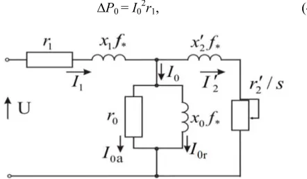
In figure 1, the equivalent circuit AD is shown in case of the frequency control. In asynchronous engines there is no special drive winding intended for creation of a magnetic flux. The magnetic flux AD is created by the reactive component I0 of current of the stator (figure 1) called by a magnetization current. Therefore for AD of loss from a magnetization current
∆Р0 = I02r1, (4)
Figure 1. The circuit of asynchronous engine substitution in case of the frequency control.
where r1– the pure resistance of a winding of the stator.
Variable losses ∆Рυ are defined by losses in copper which are proportional to a square of current of loading and the pure resistance of windings. For asynchronous engines variable losses consist of losses in windings of the stator and a rotor minus losses from a magnetization current. By operation in a zone of small slidings follows that
2 2 2
1 2 0
I
≈
I
′
+
I
,where I1 – stator current AD; – the rotor current brought to
the stator AD.
Therefore for asynchronous engines
∆Рυ = 3I2′ 2
(r1 + r'2), (6)
where – brought to the rotor phase resistance stator.
For the further analysis it is convenient to pass to the relative units – to the attitude of the current variable value towards its rated value. We will designate the variables expressed in the relative units in further the additional character "*", for example ω* = ω/ωн; I2* = I′2/I′2н; I0* = I0/I0н.
We will designate the relative value of component losses for a rated operation mode of electro motors as follows:
kυ* = ∆Рυн/∆РΣн; kc* = ∆Рc.н/∆РΣн; kст* = ∆Рст.н/∆РΣн;
kо* = ∆Ро.н/∆РΣн; kм* = ∆Рм.н/∆РΣн.
∆Рυ* = kυ*I*2; ∆Рc* = k0*I20* + kст*f*βФ2* + kм*ω*n. (8)
Connection between current of loading and the moment on a shaft of the engine has the form:
М = сФI'2 sinφ2, (9)
where φ2 – a corner between vectors of current of I '2 and a
magnetic flux F (current of magnetization of I0). For small sliding motion according to the vector chart it is possible it is accepted that φ2 ≈ π/2. Therefore in relative units the
interrelation between the moment on a shaft, current of loading and a magnetic flux in an air gap has an appearance:
М* = I*Ф*. (10)
For asynchronous machines angular speed of a rotor it is proportional to stator current frequency:
ω* = f*(1–s), (11)
where s– sliding of a rotor concerning the field of the stator. Taking into account (11) ratios (7) and (8) for losses it is possible to write down as follows:
∆Рυ* = kυ*µ2*Ф2*; (12) ∆Рυ* = k0*I20* + kст*ωβ*Ф2*+ kм*ωn*. (13)
and a magnetic flux F are usually known. Connection between these values, is defined by a magnetization curve [5, 8]. If the engine works at the line section of a magnetization curve (I0 = F), then the flow in case of which
losses are minimum, is defined from a condition
d∆
P
∑*/dФ* = 0, (14)ord∆Рс*/dФ* = -d∆Рυ*/dФ*. (15)
From (12) – (15) we receive that
d∆Рυ*/dФ* = -2kυ*М
2
*Ф
3
*; (16) d∆Рυ*/dФ* = 2Ф*(kυ* + kстωβ*). (17)
At the joint decision (15) – (17) we receive value of a stream at which losses in the engine are minimum for preset values of M * and ω*:
2 *
опт* *
0* ст* *
Ф
M
k
vk
k
ω
β=
+
. (18)We will receive full losses for an optimum stream from (12) and (13) when performing a condition (18)
∆
P
∑min*=
2
M
*k
v*(
k
0*+
k
ст*ω
*β)
+
k
м*ω
*β . (19)Losses in engines at a nominal stream are defined from (12) and (13) for Ф * = 1
∆PΣ* = M*2kυ* + ko* +kcт*ω*β +kм*ω*β. (20)
With use of expressions (19) and (20) we will analyze change of losses in the engine in various operating conditions of the electric drive.
1. The engine works at rated speed (ω* = 1) with various moments on a shaft (M * = var).
For M = Mn (M * = 1)
∆PΣ* = kυ* + k0* +kcт* +kм*; (21)
∆
P
∑min*=
2
k
v*(
k
v*+
k
ст*)
+
k
м*. (22)These losses differ slightly as (21) characterizes nominal power setting which with power the point of view is near optimal with losses (22).
During the work in the idling mode (M * ≈ 0)
∆Р∑* = k0* + kcт+ kм*; (23)
∆Р∑min* ≈ kм*. (24)
Thus, regulation of a flow in case of an alternating load and constant speed of the electric drive allows to reduce losses by value no more (kυ* + kst *) time that makes 20 … 50% of complete losses in the rated mode.
2. The electric drive provides regulation of speed of the engine (ω* = to var) in case of the rated moment on a shaft
(M * = 1).
For rated speed (ω* = 1) ratios (21) and (22) are fair. For small speed (ω * ≈ 0) these ratios have an appearance:
∆Р∑* ≈ kυ* + kо*; (25)
∆
P
∑min*≈
2
k k
v* 0* . (26)It will easily be convinced that in case of kυ* = k0 * values ∆PΣ* = PΣmin * i.e. if rated values of variable losses kυ* and losses from k0 magnetization current * are identical, then opportunities for lowering of summary losses are absent here.
Optimization of the frequency and adjustable asynchronous electric drive with ventilator loading. In the frequency and adjustable asynchronous electric drive implementation of methods of minimization of losses is more complex challenge as formation of a flow in the asynchronous machine requires use of special sensors or difficult control algorithms [9, 12].
If saturation of a magnetic conductor isn't considered, then:
Ф* = Е*/f*, (27)
i.e. regulation of a stream assumes need of maintenance of the required E*/f* ratio.
According to (18) magnetic flux of Фopt * is defined by the
M moment * on an engine shaft
М* =Ф*I'2*sinφ2, (28)
where φ2– a corner between Ф * and I' 2 * which at small values of sliding of s is equal approximately π ⁄ 2, i.e.
М* ≈ Ф*I'2*. (29)
Фопт* ≈
* 2
* ст* * ′
+
vv
k
I
k
k
ω
β . (30)Uopt* tension size this stream, necessary for creation, pays
off as follows:
U* = Е*+I1*Z1* ≈ Ф*f*+ I1*z1*, (31)
where 2
(
)
21* 1* * 1*
z
=
r
+
f x
;z
1*=
z
1/
z
1н ;1* 1
/
1нr
=
r
z
;x
1*=
x
1/
z
1н;z
1н=
U
н/
I
1н.In the asynchronous electric drive with ventilator loading, the moment on a shaft HELL is a single-valued function of rotational speed of the engine. In this case a magnetic flux of Фopt * and Uopt respectively tension * are defined only by
angular speed ω* and f* frequency.
Фопт* ≈f*
* 4
* * *
v
v ст
k
k
+
k
f
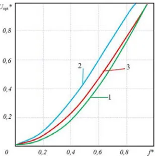
β . (32)The approximate type of dependences of Fopt * (*) and Uopt * (f *) for M * = ω2 * is shown to f in figure 2.
Figure 2. Diagrams of dependence of the relative values of a magnetic flux.
and tension from the frequency of Фopt * (f *) and Uopt * (f *)
for mechanisms with the ventilator moment.
Development of the system of management of the energy
saving electric drive with ventilator loading. Dependence of current of the stator of the engine on his tension to have extreme character at the constant moment of loading that allows at reduction of loading on an engine shaft below nominal at the constant moment of static resistance, to reduce consumed current and to increase power factor of the engine having reduced supply voltage [1].
This circumstance has essential value for mechanisms which for the technological reasons have to work certain time with incomplete loading of the engine. In particular, it treat mechanisms with the ventilator static characteristic at which is in the range of regulation of angular speed, for example, 4:1 powers removed from an engine shaft decrease approximately by 20 times [3].
The systems of the electric drive allowing to carry out frequency regulation of speed of the engine at any static moment of loading (in particular at casual loading) have excess complexity for electric drives of mechanisms at which the moment is unambiguously connected with angular speed. Therefore for electric drives with ventilator loading it is expedient to use other system of regulation that will allow to achieve a certain simplification and reduction in cost of system of the electric drive.
In figure 3. the functional diagram of the offered system of the energy saving asynchronous electric drive with control on the stator current module on the basis of the EPS-OA [9, 10] electric drive is provided.
Figure 3. The functional diagram of the energy saving asynchronous electric drive with control on the engine stator current module.
The energy saving electric drive with ventilator loading turns on the frequency converter 1 consisting of the transistor pulse-width regulator 2 with two force transistors keys 3 and 4, the thyristor inverter 5 with the reverse diodes 6, two current sensors 9 and 10, two constant resistors 11 and 12, and the unit 7 of control of operation of the frequency converter 1 is executed in the form of the relay circuit of comparing 13, the generator of an algorithm of switching of 14 thyristors 8 of the inverter 5, the pulse width modulator 15 and the generator of an algorithm of switching of 16 transistors of force transistor keys 3 and 4, the voltage sensor 18, the voltage controller 19 and the function generator 20.
The device for control of the electric drive works as follows. The diagram of the device with control on the module of current of the stator [2] allows to set Uex/fex ratio
parametric, i.e. fex frequency on an output of the thyristor
inverter (engine stator tension frequency) is set automatically depending on loading on a shaft of the asynchronous engine and a signal of installation on the engine stator Im current module.
At the same time time of frequency control of fex in case of
change of the controlling influences makes value 1/f0. where
f0 – switching frequency of thyristors of the inverter. Output
fex = to f0/6. During this time even on rather low frequencies
the electromagnetic flow of a rotor of the asynchronous engine owing to the considerable constant of time doesn't manage to change significantly, than the range extension of regulation of speed is provided.
The parametric job of frequency excludes also need of any limit of current as restriction of current happens automatically. Feature of this electric drive is also existence of the moment on a shaft of the fixed engine. The function generator in the diagram sets the required correlation between Uopt and fex in compliance with expressions (31) and
(32). The type of the relative dependences of Fopt * (*) and
Uopt * (fex *) for mechanisms with the ventilatory moment of
resistance is shown to fex in figure 2. The voltage controller,
comparing optimum Uopt(γ) and leaking values of tension of
the stator of the engine from the voltage sensor, influences the frequency converter so that to provide their equality and to receive Фopt required value of an optimum flow for
minimization of losses in the drive.
Dependences of Uopt * (fex*) the illustrating curves realized
by the FP functional converter and calculated by the offered technique for various engines at ventilatory loading are given in figure 4. Figure 1 has designated two almost coinciding curves for a case of use of engines of a series 4A (4A250M4 and 4A100M6) with a power respectively 2,2 and 90,0 kW and 2r = 4. Apparently, the received curves are extremely simple for practical realization. By figure 2 it is designated for the special frequency and adjustable MAP-642-4 electric motor with a power of 90,0 kW. In this case absolute values change a little, but the configuration of a curve remains former that leads only to adjustment of the FP parameters. The curve 3 corresponds to the engine 4A250M4 at the real ventilator mechanical characteristic
М* = М0*– (1–М0*)f2вых*, (33)
where M0 * = 0,08. The form of a curve 3 is identical to
previous. In figure 5 the simplest diagram for practical implementation of the functional dependences of figure 4 is figured. At the same time the initial curve is approximated by the broken line consisting of three segments. Apparently, it rather precisely can reproduce the required curves and their adjustment by voltage variation of actuating of voltage reference diodes of VD1 and VD2.
The pilot studies of the system of the electric drive minimizing losses of engine capacity. This system of extremal control is realized on the basis of the frequency converter with the transistor voltage controller and the thyristor independent inverter of tension. The control range of angular speed in case of the ventilatory moment of loading makes 12:1 in case of rigidness of mechanical characteristics above, than rigidness of natural mechanical characteristics in all control range.
The pilot study of the asynchronous electric drive of the centrifugal META-11-JS-65s pump by the offered control unit and with the A42-6 engine is conducted. Power of the drive engine of Rn = 1,7 kW, rotational speed of nn = 980 RPM.
Figure 4. Calculated dependences of optimal tension of Uopt * from the output frequency of the -inverter of a row of types of asynchronous engines: 1 – asynchronous engines of a series 4A (4A250M4 and 4A100M6), 2 – special frequency and adjustable electromotor MAP-642-4, 3 – the engine 4A250M4 in case of the real ventilator mechanical characteristic
Figure 5. Scheme of the functional converter for realization of dependence of Uopt * (fex*).
The experimental energetic characteristics AD on summary losses ∆Рdv *(M*) for adjustable and energy saving
electric drives are provided on figure 6. Experiments showed that, efficiency of extremal regulation is especially strongly shown in case of small loadings (M *<;0,5), in the idling mode in case of control with energy saving of loss of power in the engine more than 20% decrease. Similar results are received as well in case of values of frequencies of power voltage below rated.
Figure 6. Energetic characteristics of the asynchronous engine on summary losses ∆Рдв * (M *): and – the adjustable EPS-OA electric drive: "______"– the energy saving electric drive with control to the stator current module: "__ __ __".
are given (f * = 1). These dependences of the relative values of current of the stator (I *), engine electrical power factor (cosφdv *) and complete losses of the engine (∆Р *) as the
relative power on its shaft Rdv * (solid lines) and the mode of regulation on the law U/f = const (dotted lines). Apparently, efficiency of extremal regulation practically comes to light only in case of M*<0,5, but in case of regulation on a minimum of losses of power the electrical power factor of the engine increases in the mode of idling of the engine almost three times, current of the stator and loss decrease more than twice, similar results are received as well in case of values of frequencies of power voltage below
rated.
In the figure 7. the experimental dependences of the relative values of current of the stator (I *) and engine electrical power factor (cosφdv *) functions of the relative
moment of the engine are given (M *) with a frequency of power voltage of 10 Hz (f * = 0,2 continuous curves). Here, also as well as in the previous case comparative dependences of the mode of regulation on the law U/f = const (dotted curves) in a zone of low loading of the engine are this, i.e. in regime of the close to idling the electrical power factor of the engine raises twice, and current of the stator decreases also almost twice.
Figure 7. The experimental statistic characteristics of the electric drive with a frequency of 50 Hz and 10 Hz.
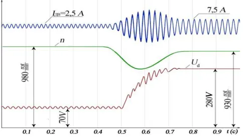
The oscillogramsare provided on figure 8 and illustrate some dynamic properties of system. In figure 8 process of aemission of load rating on the idling engine in case of rated frequency of power voltage and change is figured at the same time of current of the Idv engine and rotational speed of n.
Apparently, the enclosed perturbation is fulfilled for 0,3 with in case of "fit" of rotating speed to 28%.
Oscillograms of figure 8. illustrates the process of reset of load rating. On rotational speed establishment transient phenomenon comes to an end for 0,07s, however tension is set approximately for 1s.
Figure 8. Oscillogram of an emission and fall off a rated load.
Regulations in sizes of currents and tension are practically absent, and the system passes into economy mode of work with the lowered magnetic flux of the engine.
Estimating the received results, one may say, that the system of the frequency and adjustable extreme electric drive minimizing losses of engine capacity has good energy saving, and also satisfactory dynamic properties. And efficiency of use of this system of the electric drive of subjects is more, than the periods of idling of the engine are more long.
aren't imposing increased requirements to dynamics of the drive and in too time for some the operating mode with incomplete loading of the engine is characteristic.
References
[1] Aripov N. M., Ismatkhodzhayev S. K., Usmonov Sh. Yu. The energy saving frequency and adjustable asynchronous electric drive with ventilator loading//the Uzbek log of the Problem of informatics and power engineering. – Tashkent, 2011. – No. 2. Page 74-76.
[2] Aripov N. M., Usmonov Sh. Yu. Development of the energy saving frequency and adjustable asynchronous electric drive with ventilator loading.//Electrician. 2011. No. 4. – Page 26-28.
[3] Braslavsky I. Ya., Ishmatov Z. Sh., Polyakov V. N. The energy saving asynchronous electric drive / Under the editorship of I. Ya. Braslavsky – M.: Academy, 2004. – 256 with.
[4] Bulgakov A. A. The frequency control of asynchronous electromotors. M.: Energoizdat, 1982. – 216 with.
[5] Geyler L. B. Electric drive bases, – Mn.: Vysheysh. school, 1982. – 237 pages.
[6] Ilinsky N. F., Moskalenko V. V. Elektroprivod. Power and resource-saving. – M.: ACADEMA, 2008. – 208 pages. [7] Ilyinsky N. F., Rozhankovsky Yu. V., Gornov A. O. Energy
saving. in the electric drive. – M.: Vyssh. шк., 1989. – 127c. [8] Kostenko M. P., Piotrovsky L. M. Electrical machines, M:
Energy, 1973. P. 2., 648 pages.
[9] Petrov L. P. Optimum control of the electric drive. – L.: Energy, 1971. 187 pages.
[10] Sandler A. S, Sarbatov R. S. Automatic frequency control of asynchronous engines. - M: Energy, 1974. - 328 pages. [11] Shreyner R. T., Polyakov V. I. Extremal frequency control of
asynchronous engines//Electrical engineering. – 1973. – No. 9. – Page 10 - 13.