MATERIALS AND TECHNOLOGICAL DEVELOPEMENT OF SCREEN
PRINTING IN TRANSPORTATION
Eszter Horvath1, Gabor Henap2, Gabor Harsanyi3
1, 3 Department of Electronics Technology, Budapest University of Technology and Economics, H-1111
Budapest, Goldmann Gy. 3., building V2, Budapest, Hungary
2 Department of Applied Mechanics, Budapest University of Technology and Economics,
H-1111Műegyetem rakpart 5., building MM, Budapest, Hungary Received 21 December 2011; accepted 1 February 2012
Abstract: Screen printing is a widely used technology in electronic technology. Even though there were many developments in the technology, it is still being under improvement. This paper deals with the automotive industry related screen printing processes. The processes associated with layer deposition and the manufacturing process parameters, which affect the quality of the prints. As the repair of electronic control unit (ECU) used in road vehicles is nearly impossible the quality of printing therefore unquestionable. It is very important that the accidents caused by mechanical failure must be kept as low as possible therefore the avoidance of failure in screen printing is not only economical question but in case of transportation it is also question of road safety. Finally, an overview is given of the typical failure effect and possible causes appearing in screen printing.
Keywords: screen printing, squeegee, layer deposition, electronic control unit.
1 Corresponding author: [email protected]
1. Introduction
Automotive industry is one of the most dynamically developing sectors. However, every improvement should be handled very carefully, because an incidental failure can take human life. Therefore, quality and reliability plays a very significant role in the automotive industry. Sometimes these applications have to stand high power, temperature or mechanical stress. Therefore, thick film and LTCC (Low Temperature Co-fired Ceramics) are accepted technologies for these purposes, e.g. in ESP (Electronic Stability Program) or TCU (Transmission Control Unit) (Borgeest, 2008). They are suitable for high-performance engine control unit (Nishigaki et al., 2004), gear control units, anti-blocking breaking systems and speed control devices (Bechtold,
2009) or fuel cell applications (Partsch et al., 2006). Furthermore, polymer thick film is also utilized in the production of heated automobile mirror (Berg et al., 1983 - Patent) and seat (Ellis, 1961 - Patent). Since the realization of electric interconnection and passive elements is screen printing, the quality of the end product is conditioned by this technology. In order to achieve higher reliability of these devices, the most important technological process has to be deeply understood.
1.1. History of Screen Printing
millennium it is still under development and there have been many innovations with the technology in the last 50 years (Kosloff, 1987). The technology has a large application field as varied as decal fabrication, balloon and cloths patterning, textile fabrication, producing signs and displays, decorative automobile trim and truck signs and last but not least printed electronics, including circuit board printing and thick film technology. These circuits are wildly used in nowadays vehicles. Screen printing technology offers widespread and inexpensive way to realise high-density circuits (Horvath, 2008). Manual screen printing can be carried out by using only a frame, a screen, a squeegee, and paste or ink. While the automatic variant requires screen printer equipment, it significantly speeds up the process.
2. Methodology – Applications and
Materials
In the production of printed wiring boards, the printing is usually based on this screen printing technology. Each application field requires a thorough investigation of the screen properties before selection the right screen type. It can happen that one type of screen fits in only with one application. First, the material of the screen has to be determined. The most common materials used for screens in transportation are polyester and metal. Polyester and metal mesh are the most widespread screen fabric because polyester is widely used for its versatility and cheapness while metal mesh (made of stainless steel, copper, bronze, or brass) is the most durable fabric utilised for mass production and also appropriate when plastic substrates are printed with heated inks (Board, 2003). At the screen selection, further parameters have to be given. Two types of thread are available: multifilament or monofilament. Monofilament
type provides better quality than multifilament type avoiding prints with uneven edges but they are more expensive than multifilament threads. Another parameter of the screen is the mesh count, which is the number of threads per linear inch. The higher is the mesh count the finer details and higher quality can be produced. The diameter of the thread plays also a significant role in the screen printing. A larger thread diameter provides higher strength to the fabric, but the overlaying induced by the filaments results in worse print quality. Nevertheless, we cannot forget about weave patterns. Three types of weave patterns are applied in this technique (Fig. 1): • Plain is the simplest type of weave. A single
weft is progressively passed over one warp and under the next warp. It is suitable for most applications.
• Twill is similar to plain weave in that the weft passes over and under warp threads. However, warp yarns are skipped at predetermined intervals. It is the best choice if the quality is not so important because it is the cheapest solution. • Gauze is created as pairs of warps are
alternatively crossed over one another and secured in position as the weft thread passes through. It can be used for long runs because of its strength.
cleaning. Etched metal mask can be the solution of this problem but it is much more expensive but it is not reusable. The frame is also an important element of the screen-printing process, however, it is virtually useless. Screen frames are available in many sizes, shapes, and profiles. They are made of many different materials, including wood, aluminium, magnesium, and steel. Despite of their features, all screen frames are required to withstand the force of the tensioned screen and the additional forces applied during printing remaining flat and square being light enough to handle easily. For example, a 30 cm*30 cm screen with the tension of 30 N/ cm has to stand of approximately 900 N along each side or beam of the frame (30 cm*30 N/ cm=900 N). Obviously, the load increases proportionally to the frame size. If the frame is not appropriate bowing or twisting, effects of the frame can occur (Kiddell, 2000).
3. Analysis – Variation and Parameters
of Screen Printing
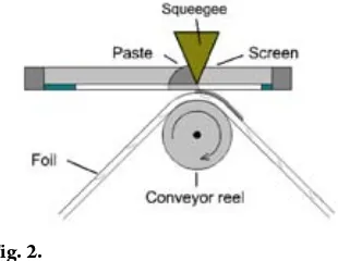
The printing method can be carried out in two ways: the common flatbed printing, which is suitable for flat rigid substrates and the flatbed cylinder printing (Fig. 2) can be applied for longer runs of flexible substrate.
The screen printing process consists of forcing ink through a mask covered fabric or wire
mesh, which has been mounted, in a strong frame.
There are two main technique of the screen printing:
• off-contact, where the screen is warped with a given tension above the substrate; • contact, where the screen is in full contact
with the substrate.
Contact screen-printing is less advantageous in general, because due to the lift off of the screen it is often detected damage of the high resolution pattern. In case of off-contact screen-printing, some paste is applied on top of the screen in the front of the polymer squeegee. While the squeegee is moving
Fig. 2.
Flatbed Cylinder Printing Source: Authors
Fig. 1.
Different Weave Patterns in Screen Printing: a) plain b) twill c) gauze Source: Authors
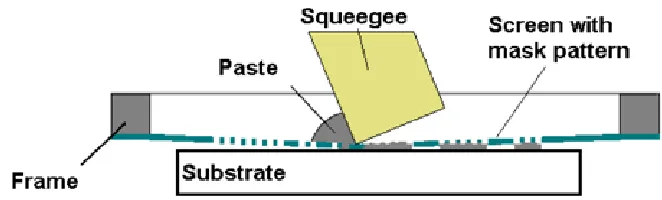
forward, it deforms the screen downwards until it comes into contact with the substrate beneath. The paste is pushed along in front of the squeegee and pushed through the screen not covered by emulsion pattern onto the substrate. The screen and substrate separate at behind the squeegee. The flatbed off-contact screen printing process is demonstrated in Fig. 3.
The quality of the image depends on several parameters.
Squeegee pressure: At the determination of the optimum squeegee pressure, a few parameters should be assumed. The squeegee force has to overcome the force which is necessary to press the paste through the screen, which depends on the hardness of the squeegee material hardness, the squeegee angle, the warp thickness, spin off height, screen tension, the ratio of and the blade length and mask layout size. The squeegee force has to be high enough to contact whole edge. Although as a consequence of too high pressure the squeegee deforms and prematurely destructed. Due to the large number of factors, the factual value of the squeegee pressure is not possible to determine: it can be specified by trial and error method. By increasing the squeegee pressure, - length and – flexibility the squeegee has a definite wave line from top view. If the
shape of the squeegee line differs from the straight line such a way, it leads to bulging printed layer in the middle the printed image – depending on the type of paste, the flow - and rheological properties of the paste. In order to achieve uniform paste film in the whole width of the printed layer the squeegee has to be only moderately flexible. The ratio of the squeegee length and the mask layout size plays an important role because the force against spin-off is much higher if the end of the squeegee is close to the frame. Advantageous situation can be approached if the size of the screen is twice of the mask layout size. Furthermore, changing the squeegee pressure results in different printed layers and the elongation of the screen can cause aligning failures as well. Speed of the squeegee: The finer is the mask resolution the lower should be the squeegee speed. If the printing speed is too high, the squeegee cannot spin out the paste regularly but a thin paste film is left back in the screen, which can cause distortion of the printed layout and paste smearing.
Off-contact set: After coarse positioning of the pattern the distance between the substrate and the screen should be checked ( Jerzy et al., 1990). Incorrect distance adjustment can cause the following failures:
Fig. 3.
a) contact distance is small:
- During screen printing the screen sticks down, causing a significant thickening of the paste at the sticking place;
- Sticking down can induces print-distortion, - Due to higher squeegee pressure the printed pattern is blurred,
b) contact distance is large: - The print is incomplete;
- The thickness of the printed layer is uneven and thin;
- The screen is permanently elongated due to too large squeegee pressure;
- The imprint distorts, the positioning accuracy (reverse direction) decreases;
- Fine adjustment can not be done properly. Squeegee shape: Squeegees are usually made of polyurethane or other elastomers. First, they are cast in liquid form, then cut and milled in order to create sharp edges. The squeegee material is delivered to the users in rolled form for shipping and for the actual application. In the process of screen printing the squeegee has to perform few tasks but these tasks are
influenced by many of parameters. First, the squeegee forces the ink into the mesh, but it is influenced by the ink viscosity and mesh opening. In order to deposit the ink onto the substrate screen has to be in contact with the substrate, however, too high screen tension and high off-contact distance can prohibit it. Furthermore, squeegee removes excess paste from the screen so the thickness of next printed layer and the image quality as well. In order to find the right squeegee for our process three parameters of the squeegee have to be selected:
• hardness, • profile, • edge shape.
In general, we can state that hard squeegees transmit more force than soft ones while soft squeegees have higher adaptability to the surface of the substrate.
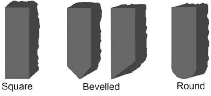
By modifying the profile (Fig. 4) of the squeegee the value of the force transmitted to the printing surface can be limited.
Fig. 4.
Fig. 5.
Sharper Edge Shape Increases the Image Resolution and Decreases the Paste Thickness Source: Authors
In addition, this shape influences the effective squeegee angle. The set angle differs from the effective squeegee angle, which is the angle between the screen and the substrate, because the squeegee bends due to the load. If the effective squeegee angle is small, more ink is pushed through the screen ahead of the squeegee and the less ink is scraped from the surface of the screen. Square profile is the most commonly used profile in screen printing which provides medium adaptability but maximal force and the effective angle the set angle are about the same. However, the effective angle is always less than the set angle in case of bevelled edges. This construction provides the best adaptability and minimum force. The effective angle of bevelled profiles is always less than the set angle. Round profile squeegee has low adaptability, transmits minimum force and the effective angle is always very small and hardly affected by the set angle. The sharpness of the squeegee can be set by the edge shape (Fig. 5).
Edge shape establishes the amount of ink delivering to the substrate. Sharper edge
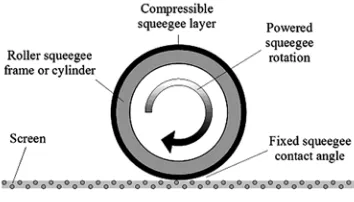
delivers less ink and the amount of deposited ink influences the resolution of the printed image, because less ink results in sharper image. In order to achieve best quality in printing the different squeegee hardness, profile and edge shape can be combined (Frecska, 1999). Another solution can be so called roller squeegee (Anderson, 2003). Substituting the conventional squeegee by a roller squeegee (Fig. 6) higher printing speed can be achieved and an excellent and consistent paste thickness is also ensured.
Fig. 6.
4. Discussion – Typical Failures in Screen
Printing
It is very important to detect and classify the different failure types of screen printed image. If we detect the problems and collect the data or documenting failures occurred in the process we have good chance to confine the failure mode. Print definition faults are one of the most often problem (Krammer et al., 2012), (Legén et al., 1986):
1. Ragged edges/sawtooth: this fault usually shows as saw edge with pitch equal to mesh spacing.
This problem can be originated in poorly made or worn screen or rough substrate surface. 2. Smeared edges:
2.a. Smearing on only certain parts of pattern. Irregularities on screen surface. 2.b. Overall smearing but mainly in direction of squeegee travel. Low screen tension or snap-off too low.
2.c. General overall smearing. Ink viscosity too low, rough substrate surface, badly worn squeegee or angle of attack too low. Too much squeegee pressure or unwanted screen or substrate movement during printing.
3. Incomplete pattern:
3.a. Areas completely missing, particularly near the trailing edge of the pattern. Insufficient ink.
3.b. Failures always in same place. Faulty screen.
3.c. Print patchy and missing in depressions in substrate surface. Down pressure too low
or incorrect or incorrect down stop setting. 3.d. Thin print, missing in parts. Squeegee transverse too fast.
3.e. Print thin and incomplete near trailing edge. Snap-off too low or squeegee lifting too soon or screen blocking occurred. 3.f. Print patchy as in 3.c and 3.d. Ink viscosity too high, squeegee too hard, attack angle too high.
3.g. Fisheye: A small round or oval imperfection with a dark center. This problem is usually caused by ink/substrate incompatibility.
3.h. Mottling: A faint, irregular pattern in the image area. That is caused by either differing rates of ink absorption into the substrate or minor differences in substrate thickness.
3.i. Pinholes: Small printed dots in the non-image areas. Caused by a poorly processed stencil.
Print thickness faults can also appear (Frecska, 2002), (Holmes et al., 1976):
1. Print generally too thin Incorrect choice of screen mesh, squeegee transfer speed is too high or ink viscosity too low (over-thinning or temperature effect can change the paste theology), angle of attack too high.
2. Uneven print thickness
2.a. Prints are consistently thin on one edge or at one end. Screen/squeegee/substrate not parallel.
2.c. Thin patches with pronounced mesh markings usually near trailing edge of print. Screen tension or snap of too low, squeegee lifting too soon.
2.d. Thin in patches, usually in depressions in substrate surface. Down pressure too low, incorrect down stop setting, squeegee too hard, insufficient ink.
2.e. Prints locally thick in streaks where ink trailed behind squeegee. Ink behind squeegee.
3. Prints too thick.
Incorrect choice of screen mesh or squeegee pressure too high.
3.a. Often accompanied by smearing of print edges. Attack angle too low, snap-off too large or too much ink on screen.
5. Conclusion
Screen printing is widely used to realize desired images on several surfaces while the process parameters and the materials involved are varied for each process of automotive products. The technology is still requiring developments due to higher and higher demands. The ease of construction and the low cost makes screen printing commercial layer deposition method in the field of labels, electronics and automotive industry. The highest quality ECUs used in transportation or in road vehicles produced in such a way.
Acknowledgements
This work is connected to the scientific program of the “Development of quality-oriented and harmonized R+D+I strategy and functional model at BME” project. This project is supported by the Szechenyi Development Plan (Project ID: TÁMOP-4.2.1/B-09/1/KMR-2010-0002). The authors would like to thank Hatvan – Robert Bosch Elektronika Ltd. for funding the work.
References
Anderson, J. 2003. Forecasting the Future of Screen-Printing Technology, Screen Printing Magazine. Available from Internet: < http://www.screenweb.com/content/ forecasting-future-screen-printing-technology#. T7ntPlKf YfU>.
Bechtold, F. 2009. A Comprehensive Overview on Today’s Ceramic Substrate Technologies, 17th European Microelectronics and Packaging Conference, 1-12.
Berg, P.G.; Strobel, S.J. 1983. Patent number: US4410790, Heated automobile mirror, Texas Instruments Incorporated. Available from Internet: <http://www. google.com/patents/US4410790?printsec=abstract#v= onepage&q&f=false>.
Board, N. 2003. Screen Printing Technology Hand Book, Asia Pacific Business Press. 742 p.
Borgeest, K. 2008. Electronics in automotive engineering [Elektronik in der Fahrzeugtechnik], Hardware, Software, Systeme und Projektmanagement, Vieweg, Wiesbadem. 357 p.
Ellis, L.L. 1961. Patent number: US3013141, Seat heater. 2 p.
Frecska, T.S. 2002. Screen-Printing Troubleshooting Glossary, Screen Printing Magazine. Available from Internet: <http://www.screenweb.com/content/ squeegees?page=0%2C1#.T7nv91Kf YfU>.
Holmes, P.J.; Loasby, R.G. 1976. Handbook of thick film technology, Electrochemical Publication Ltd. ISBN 0901150053. 430 p.
Horvath, E. 2008. Embedded thick-film resistors applied in low temperature co-fired ceramic circuit substrates,
Periodica Polytechnica Electrical Engineering 52(1-2): 45-57.
Jerzy O.A.; Howland, F.L. 1990. A Study of the Off-Contact Screen Printing Process – Part I: Model of the Printing Process and Some Results Derived From Experiments,
IEEE Transactions on Components, Hybrids, and Manufacturing Technology 13(2): 358-367.
Kiddell, P. 2000. The ScreenFrame: Foundation of the Process, Screen printing magazine.
Kosloff, A. 1987. Photographic Screen Printing, ST Publications, Cincinnati, Ohio. 311 p.
Krammer, O.; Molnár, L.M.; Jakab, L.; Szabó, A. 2012. Modeling the effect of uneven PWB surface on stencil bending during stencil printing process, Microelectronics Reliability 52(1): 235-240.
Legén, L.; Valló P. 1986. Screenprinting – I. part [Szitanyomtatás I. rész], Híradástechnika 37(3): 127-142.
Nishigaki, S.; Goebel, U.; Roethlingshoefer, W. 2004. LTCC (LFC) material systems and its application in automotive ECU’s. In Proceedings of the Conference on Ceramic Interconnect Technology: The Next Generation II, Denver, CO, USA, paper WP32, 432-433.
Partsch, U.; Goldberg, A.; Stelter, M. 2006. LTCC-Based Micro-Scale PEM Fuel Cell, Electronics Systemintegration Technology Conference Dresden, Germany, 544-549.
M A T E R I J A L I I T E H N O L O Š K A
U N A P R E Đ E N J A T E H N O L O G I J E
SITO ŠTAMPE KOJA SE KORISTI U
TRANSPORTU
Eszter Horvath, Gabor Henap, Gabor Harsanyi
Sažetak: Tehnologija sitoštampe je široko zastupljena u elektronskoj tehnologiji. Pored dosadašnjeg značajnog razvoja, ova tehnologija se i dalje unapređuje. Ovaj rad se bavi procesima tehnologije sitoštampe u automobilskoj industriji. Ovi procesi su u vezi sa nanošenjem slojeva i parametrima procesa izrade koji utiču na kvalitet štampe. Kako je popravka elektronske kontrolne jedinice (ECU) ugrađene u drumska vozila gotovo nemoguća, kvalitet štampe mora biti neosporan. Veoma je važno da broj nezgoda koje su nastale kao posledica mehaničkih oštećenja sitoštampe bude što je moguće manji, pa zbog toga izbegavanje greške u sitoštampi predstavlja ne samo pitanje ekonomičnosti već i bezbednosti drumskog transporta. Na kraju ovog rada dat je pregled uobičajenih grešaka u sitoštampi i mogućih uzroka njihovog nastanka.