[Oscar et al., 5(10): October, 2018]
ISSN 2349-0292
Impact Factor 3.802
GLOBAL JOURNAL OF ADVANCED ENGINEERING TECHNOLOGIES AND
SCIENCES
DESIGN AND DEVELOPMENT OF A PORTABLE ELECTRONIC SYSTEM FOR
BIOMECHANICAL ANALYSIS
Oscar O. Sandoval-Gonzalez*, Joshua A. Flores-Perez, Gerardo Aguila-Rodriguez, J.J. Agustín
Flores-Cuautle, Blanca E. Gonzalez-Sanchez, Albino Martínez-Sibaja
*
Prof. Dr., Postgraduate Department, Tecnológico Nacional de Mexico/Instituto Tecnológico de
Orizaba
M.Sc. Student, Postgraduate Department, Tecnológico Nacional de Mexico/Instituto Tecnológico de
Orizaba
Prof. Dr., Postgraduate Department, Tecnológico Nacional de Mexico/Instituto Tecnológico de
Orizaba
Prof. Dr., CONACYT-TecNM/ I.T.Orizaba
Prof. Dr., Postgraduate Department, Tecnológico Nacional de Mexico/Instituto Tecnológico de
Orizaba
Prof. Dr., Postgraduate Department, Tecnológico Nacional de Mexico/Instituto Tecnológico de
Orizaba
DOI: 10.5281/zenodo.1475814
ABSTRACT
The present work includes the design and development of a portable electronic system with the capacity of acquiring information of the human body biomechanical parameters which are obtained through inertial sensors and modules of force templates.
KEYWORDS: Biomechanics Analysis, Force Sensors, Inertial Sensors.
INTRODUCTION
Biomechanics is a multidisciplinary area of knowledge which studies the human body along with its behavior, changes, phenomena and laws applied to the studied body from the mechanical point of view, having a great impact in society, and being of great relevancy in different areas of interest. Biomechanics is used in medical, industrial y sport areas among others. Nowadays there are systems of high technology focused on capturing movement, however; most is restricted to laboratory conditions and at a high cost, not mentioning that highly trained personnel es required to manipulate this kind of systems.
Analyzing the human body at a biomechanical level presents a great difficulty nowadays due to the current systems used, besides the wide experience needed to manipulate them. Lately, technology has increased the demands on quality and reliability at acquiring information related to the human body making areas such as industry, medicine and sports adopt new systems. The photogrammetry is implemented in some cases to study the biomechanical analysis of the human body, it involves numerous tools to obtain quantitative parameters such as the case of A. Moreno [1] where the human march is studied by using the videogrametry, electromyography and dynamometer techniques, making a plan and configuration at a laboratory, highlighting the selected tools as the most implemented nowadays. That same work considers that to obtain an efficient analysis, methodologies so as the usage of 6 cameras and a platform of strength with a Gait Eliclinic® software, as well as the characterization of the time and cycles of the equipment use and the location of markers are necessary.
[Oscar et al., 5(10): October, 2018]
ISSN 2349-0292
Impact Factor 3.802
occlusions and being able to detect an arbitrary number of people in a scene pointing out the need to keep developing a future promising work compared to other Photogrammetry systems.Inertial sensors (Imu) are broadly used in different areas of study because of their simplicity, low cost and reduced size. An example of area of study was implemented by Gnerlich [4] where an inertial sensor was done to experiment with Biomechanical cells. Its manufacturing process is simple, besides being sensitive, it highlights the size and the manufacture of the device so as the comparative tables of the piezoelectric size - sensor in micrometers and is functioning. The inertial sensor has an phenomena called drift where is impossible to estimate the position of a person, Eric Bechmann [5] presents an algorithm to estimate the position, carrying out the experiment where the user ran a trajectory of 100 and 400 meters of distance, this algorithm reduced significantly the effect of the drift in the sensor, improving the quality of data acquisition. Another method to reduce this drift effect was developed by J.C. Alavarez [6] where the estimation of the traveled distance is estimated using the fusion of sensor with a Kalman Filter to reduce de drift effect of the sensor producing a better estimation of the distance. The embedded systems of the inertial sensors are commonly used in the biomechanical analysis, Taylor [7] carried out a network of IMU sensor using Wireless communication, this system was used in the lower limbs. Frisoli [8] developed a Wireless communication using a ZigBee protocol, the inertial sensors were used to obtain biomechanical variables of the human body, these experiments were analyzed and validated using a video graphing system.
The present work implements a fusion of sensors to estimate in one hand the angular movements and in the other hand the feet force. The system indicates a great use in the biomechanical analysis of the human body due to it is easy to handle and practical because there is no need of laboratories, improving the quality and accuracy of the information treated.
MATERIALS AND METHODS
Description
The core of the system is integrated by the inertial and the force sensors, these sensors acquire the biomechanical data of the user. A microcontroller of 32 bits is the responsible to compute and estimate the angular position of the inertial sensors, and also to acquire and to process the force signals of the force sensors. This information is sent to a PC interface (LabVIEW) saving the obtained data and rendering in real time an avatar in a virtual reality scenario according to the movements that user is performing. Figure 1 shows the general diagram of the biomechanical system.
Figure 1. General description of the biomechanical system
Inertial sensors system
[Oscar et al., 5(10): October, 2018]
ISSN 2349-0292
Impact Factor 3.802
connected to these lines in the multiplexor circuits, making possible to stablish a communication between the microcontroller and the desired inertial sensor only selecting the corresponding sensor to acquire the data. Figure 2 shows the PCB of the multiplexor circuit, there are two multiplexor for the SCL and SDA signals which are the inputs of the circuit, the output of the multiplexor is the selected signal that is connected to the SCL and SDA terminals of the Microcontroller.Figure 2. Multiplexor Circuit, SCL and SDA del I2C
A motherboard was designed to integrate all the required components as is shown in Figure 3. This motherboard integrates 2 multiplexor circuits, 1 Microcontroller (Arduino Due), 5 sockets RJ-45 where all the inertial sensors are connected.
Figure 3. Motherboard target
Force foot template sensors
The force foot template sensor follows two objectives, the first one is the acquisition of the force generated by the user and second one concerns to the location of these forces in the foot area. The sensor was designed using flexible and conductive materials in order to estimate the force that the user is applying in an specific contact area. In the Figure 4 is shown the 3 materials used to build the sensor, there are two flexible materials in order to cover an protect the Velostat material (Pressure-Sensitive Conductive) that is located in the middle. The Velostat material has the property to change its conductive value according to the pressure applied.
Figure 4. Materials used to build the force foot template
[Oscar et al., 5(10): October, 2018]
ISSN 2349-0292
Impact Factor 3.802
terminals of each sensor. The outputs of these 11 pressure sensors are analog signals which are connected to the ADC inputs of the Microcontroller.Figure 5. Foot template pressure sensors
In figure 6 is shown the integration of the complete system, with the inertial sensors and the pressure sensors.
Figure 6. Integration of the IMU sensors and the foot template pressure sensors.
Optimal Placement of Sensors
One of the crucial factors for the biomechanical analysis are the optimal placement of these sensors. Therefore, is necessary take into account the human body segmentation and his principal planes. A. Godfrey [9] carry out a study with accelerometers mentioning these segments. The optimal placement of the inertial sensors depends of the activity, [10] Louis Atallah investigated the placement of accelerometers for the detection of different activities like run, walk, etc. Bo Yu [11] specifies that it should be considered the vertebra T7-T8 for the placement of the inertial sensor. Andraz Rihar [12] explains that in order to create a correct tridimensional reconstruction of a body with inertial sensor is necessary that the arm and the forearm use an inertial sensor in each section for a correct correspondence. In Figure 7 is shown the configuration implemented.
[Oscar et al., 5(10): October, 2018]
ISSN 2349-0292
Impact Factor 3.802
RESULTS AND DISCUSSION
Validación del Sistema Inercial
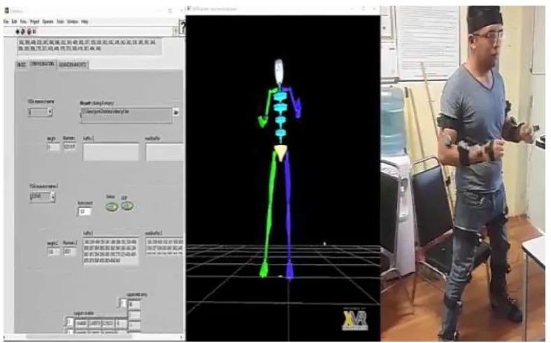
In order to validate the inertial sensors system, it was necessary to use an optical motion capture system (OptiTrack). The protocol of experimentation was integrated by a series of movements in different joints of the user (tdhe inertial sensors were placed to the user like is indicated in Figure 7). The aim of this experimentation is to obtain the motion capture data of the OptiTrack and data of the inertial sensors to carry out the comparison. In figure 8 is shown the integration of the whole system during the experimentation. It is appreciated that the inertial sensors are placed to the user using the optimal placement of the sensor. A graphical interface programmed in LabVIEW creates a communication with the microcontroller and acquires the data related to the sensor values, these values are constantly saved by the interface and are sent to the Virtual Reality software (XVR) to render a virtual avatar that moves according to his kinematics that depends of the values of the inertial sensors.
Figure 8. Experimental test using the integration of User Interface, the biomechanical sensors and the virtual reality scenario.
In the figure 9 is shown three graphs (the pitch, yaw and roll) of the right shoulder, the blue line indicates the results obtained by the OptiTrack and the pink line are de results obtained by the inertial sensor. In Figure 10 are the results of the elbow motion, the yellow line is the OptiTrack value and the green line is the inertial sensor.
[Oscar et al., 5(10): October, 2018]
ISSN 2349-0292
Impact Factor 3.802
Figure 10. Optitrack vs Inertial Sensor (Elbow movement)
Force Sensor
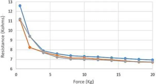
Two experimental procedures were carried out to validate the force sensors. The first test was focused in the characterization of the force sensors using gradual forces, and the second test studied the relationship between force and temperature. The repeatability, standard deviation and the mean error were computed.
For the first test, a weight from 0.565 Kg to 20Kg in 2 Kg intervals were applied to the sensor. These tests were carried out with a precision weighing machine, a press machine and a digital multimeter. In the figure 11 is presented the sensor response (Resistance) according to applied force. It can be appreciated that the repeatability in the range of 4 Kg to 20 Kg is better and more linear.
Figure 11. Sensor response (Resistance KOhms) vs applied force (Kg)
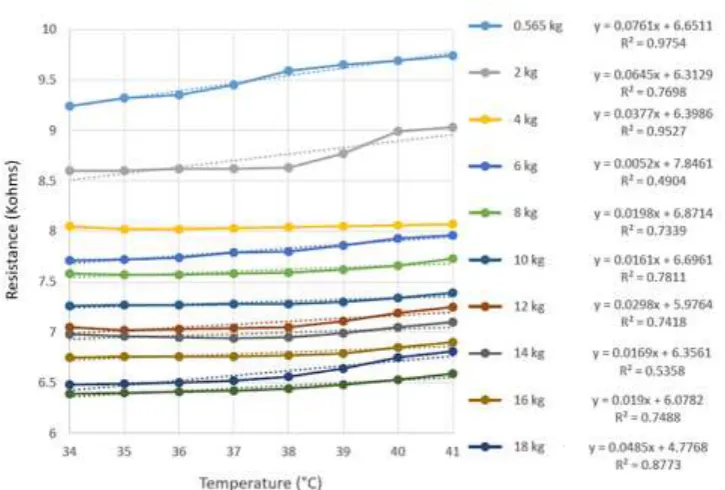
Temperature Test of the Force Sensor
[Oscar et al., 5(10): October, 2018]
ISSN 2349-0292
Impact Factor 3.802
Figure 12. Resistance vs temperature
CONCLUSION
The use of an inertial sensors network placed in different joints of the human being has the capacity to obtain the angular movements of each one of these joints with the aim to compute the biomechanical analysis of the human being. One of the principal innovations of this portable system are multiplexors in the communication protocol I2C that is capable to connect more than 15 inertial sensors at the same time, generating a complete acquisition of each one of the joints movements of the human being. The results obtained in the system indicates that the inertial and force sensors have a stable and repeatable behavior and it is possible to acquire biomechanical data in real time for different application like sports, industry and health fields.
REFERENCES
[1] Villa Moreno, Adriana; Gutierrez Gutierrez, Eduardo and Perez Moreno, Juan Carlos. “Consideraciones para el análisis de la marcha humana. técnicas de videogrametría, electromiografía y dinamometría. Rev. ing. biomed. [online]. 2008, vol.2, n.3, pp.16-26.
[2] S. Mihradi, A. I. Henda, T. Dirgantara, and A. I. Mahyuddin, “3D Kinematics of Human Walking Based on Segment Orientation,” no. November, pp. 386–390, 2011.
[3] M. Quirin, K. Kolja, and M. Buss, “A Model-based Algorithm to Estimate Body Poses using Stereo Vision,” pp. 285–290, 2008.
[4] M. Gnerlich and S. F. Perry, “A submersible piezoresistive mems lateral force sensor for cellular biomechanics applications abstract,” pp. 2207–2210, 2011.
[5] E. Bachmann, J. Calusdian, E. Hodgson, and X. Yun, “In Situ Heading Drift Correction for Human Position Tracking Using Foot-Mounted Inertial/Magnetic Sensors,” pp. 5425– 5430, 2012.
[6] J. C. Alvarez, R. C. González, D. Alvarez, A. M. López, and J. Rodríguez-uría, “Multisensor Approach to Walking Distance Estimation with Foot Inertial Sensing,” no. 2, pp. 5719–5722, 2007.
[7] T. Taylor, S. Ko, C. Mastrangelo, and S. J. M. Bamberg, “Forward kinematics using IMU on-body sensor network for mobile analysis of human kinematics.,” Conf. Proc. IEEEEng. Med. Biol. Soc., vol. 2013, no. 5, pp. 1230–3, Jan. 2013.
[8] M. A. Frisoli, C. A. Cifuentes, A. Frizera, A. Santiago, A. A. Braidot, F. De Ingeniería, U. Nacional, and D. E. Ríos, “Sensor Portable para Registro Cinemático por Comunicación ZigBee,” pp. 1–5.
[9] A. Godfrey, R. Conway, D. Meagher, and G. O, Laighin, “Direct measurement of human movement by accelerometry.,” Med. Eng. Phys., vol. 30, no. 10, pp. 1364–86, 2008.
[Oscar et al., 5(10): October, 2018]
ISSN 2349-0292
Impact Factor 3.802
[11]K. H. Bo yu, Tian Bao, Dingguo Zhang, Wendy Carender, “Determining Inertial Measurement UnitPlacement for Estimating Human Trunk Sway While Standing, Walking and Running”. .