Progress in th e A ctive D evelopm ent
o f Large Optics for A stronom y
A Thesis Submitted for the Degree
of
Doctor of Philosophy of the University of London
by
David Jon Rees
UCL
Optical Science Laboratory
Department of Physics and Astronomy
University College
University of London
ProQuest Number: 10016744
All rights reserved
INFORMATION TO ALL USERS
The quality of this reproduction is dependent upon the quality of the copy submitted.
In the unlikely event that the author did not send a complete manuscript and there are missing pages, these will be noted. Also, if material had to be removed,
a note will indicate the deletion.
uest.
ProQuest 10016744
Published by ProQuest LLC(2016). Copyright of the Dissertation is held by the Author.
All rights reserved.
This work is protected against unauthorized copying under Title 17, United States Code. Microform Edition © ProQuest LLC.
ProQuest LLC
789 East Eisenhower Parkway P.O. Box 1346
This Thesis is dedicated
to Debbie,
A b stra ct
An international consortium consisting of the United States, United Kingdom,
Canada, Brazil, Chile and Argentina are planning to revolutionize the field of astron
omy by building the two Gemini 8m astronomical telescopes. These are designed to provide unprecedented image quality, which should significantly increase our knowl
edge and understanding of the structure and dynamics of the universe. To provide
such superb image quality, the specifications of almost every aspect of the telescope
are tighter than for any other ever built.
The work described in this thesis is part of the ongoing research currently being
undertaken in the Optical Science Laboratory into the production of large, highly
aspheric optical surfaces. Meeting the design specifications for the Gemini sec ondary mirrors is believed to be impossible using conventional craft techniques, but
it is expected to be a tractable problem when utilizing the Active Lap technique de
scribed herein. The goal of the project is to demonstrate this technique by producing
a I scale model of these mirrors.
Broadly speaking, the Active Lap uses closed loop control of a system comprising of
arrays of load cells and force actuators to control the ablation of the mirror in real
time. This is a significant step forward in the field, and aims to propel conventional
craft techniques which date back to the time of Sir Isaac Newton into the 21st
century!
A m ajor contribution of the author to the Active Lap research project was the
d ata acquisition and control software, which was designed to be ergonomic and
make efficient use of cpu time. Other significant contributions involved calibration
methods, system testing, and development of the closed loop control algorithms.
In particular the novel idea of utilizing artificial neural networks to replace these
algorithms is discussed.
Finally, the performance of the Active Lap is evaluated, and suggestions are made
for both the strategy for its future use, and the investigations required for its future
C o n ten ts
A bstract 3
1 Introduction 11
1.1 Astronomical B a c k g ro u n d ... 11
1.1.1 The Gemini P r o j e c t ... 12
1.2 Technological B a c k g ro u n d ... 14
1.2.1 Conventional P o lish in g ... 15
1.2.2 Other Modern Methods of Polishing... 16
1.3 Aim of the Active Lap P r o je c t... 20
1.4 Summary of the T h e s is ... 20
2 D esign o f th e A ctive Lap 22 2.1 The Principle of Active P o lis h in g ... 22
2.2 The Active L a p ... 23
2.3 Modifications to the Initial D esign... 29
3 D escription of A ctive Lap D ata A quisition and Control Software 32 3.1 Notes on Programming Language Use and O p tim iz a tio n s... 35
3.2 User I n te rf a c e ...37
3.2.1 DOS vs W in d o w s...37
3.3 Mode S e le c tio n ...38
3.4 Graphical D is p la y s ... 39
3.4.1 General P r o p e r t i e s ...39
3.4.2 Details of each Graphical D is p la y ... 43
3.5 A ctuator C o n t r o l ... 45
3.5.1 Manually Moving the A c tu a to r s ... 45
3.5.2 Actuator R e s e ttin g ... 46
3.6 Global Force Actuator C o n tro l...46
3.6.1 Static m o d e ...46
3.6.2 Dynamic m o d e ... 46
3.7 Load Cell C o n fig u ra tio n ...47
3.8 Engineering Tests . ... 48
3.9 D ata M a n ip u la tio n ... 48
3.9.1 D ata Transfer between Lap and P C ... 49
3.9.2 Using the Analogue to Digital Conversion C a r d s ... 49
3.9.3 Timing of f r a m e s ... 50
3.9.4 Saving of data for Later A n a ly s is ... 50
4 Calibration and Testing o f the A ctive Lap 52 4.1 Calibration of the Active L a p ... 52
4.1.1 Load C e lls ... 52
4.1.2 Global Force A c tu a to rs...55
4.1.3 E n co d ers...57
4.2 Testing of the Active Lap ...58
4.2.1 Testing the Load C e l l s ...58
5 The Interpolation A lgorithm 70
5.1 In tro d u c tio n ...70
5.2 Zernike Polynomials ... 70
5.3 Using the FE A n a ly s is ... 71
5.4 Surface F i t ... 72
5.5 Nearest N eig h b o u rs... 73
5.6 Summary ... 74
6 Closing the Feedback Loop : The Real Tim e U pdates 75 6.1 In tro d u c tio n ...75
6.2 The Algorithmic A p p ro a c h ... 76
6.2.1 Experimental Verification ... 77
6.3 Using Neural N e tw o rk s... 87
6.3.1 Choosing Network P a ra m e te rs ... 88
6.3.2 Acquiring Realistic Training D a t a ... 89
6.3.3 R e su lts ... 90
7 Conclusion 98 7.1 Future D evelopm ents...99
7.1.1 The Immediate F u t u r e ... 99
7.1.2 Longer Term D e v e lo p m e n ts ...100
7.1.3 Concluding R e m a r k s ...101
A M athem atical Derivations 103 A .l Coordinate T ran sfo rm a tio n s... 103
A.2.1 Finding the Coordinates of the Ends of the Polishing Arms . . 110
A.2.2 Finding the Angle Between the Polishing Arms ... I l l A.3 Area of Lap Overhanging M irro r... 112
B A n Introduction to Neural Networks 115 B .l In tro d u c tio n ...115
B.2 General Properties of Neural N e tw o rk s ... 115
B.3 Elements of a Neural N e tw o rk ... 116
B.3.1 Units : The Building Blocks of a Neural N e t w o r k ...118
B.3.2 The Activation of a U n i t ... 118
B.3.3 The O utput of a U n it...119
B.3.4 The P attern of C o n n ec tiv ity ...120
B.3.5 The Rule of P ro p a g a tio n ... 121
B.4 Learning in Neural N etw orks...121
B.4.1 Unsupervised L e a rn in g ... 121
B.4.2 Supervised L e a r n i n g ...122
B.5 S u m m a r y ...123
A cknowledgem ents 125
L ist o f F igures
2.1 Exploded View of the Active Lap... 24
2.2 Global Force A ctuators...27
2.3 Photograph of the Active Lap...29
2.4 Exploded View of the Modified Active Lap... 30
3.1 Schematic Diagram of Active Lap Software (A )...33
3.2 Schematic Diagram of Active Lap Software (B )...34
4.1 Global Force Actuator Calibration Curves... 56
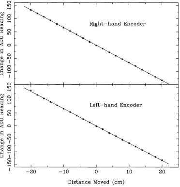
4.2 Position Encoder Calibration Curves...57
4.3 Expected pressure map when the lap is offset from the mirror, and when it is tilted by the global force actuators...59
4.4 Lap Displacement Experiment... 62
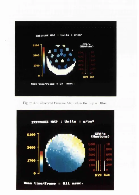
4.5 Observed Pressure Map when the Lap is Offset...63
4.6 Observed Pressure Map when the Lap is T ilted...63
4.7 Observed Pressure Map with a Central “Hot-Spot” ...64
4.8 Controlling the Position of the “Hot-Spot” ... 65
4.9 A ctuator Pulse Loss Experiment... 68
6.1 Experimental verification of FE Coupling Coeffs... 78
6.3 Ensuring the Experimental Coupling Coeffs Remain Constant with
Tim e... 80
6.4 The Response of Load Cell 3 to Different Forces from A ctuator 2. . . 81
6.5 Additive experiments with Random U pdates... 84
6.6 Additive experiments with Simulation U pdates... 85
6.7 Neural Network Expts with a Static Lap...95
A .l Coordinate transformation for position encoders... 104
A.2 Rotaional coordinate transform ation... 105
A.3 Coordinate system of displayed graphics m ap... 106
A.4 Schematic Diagram of Polishing Machine... 109
A.5 Resultant of Forces Applied to Polishing Arms... 109
A.6 Coordinates of Ends of Polishing arm s...I l l A.7 Find the Angle Between Two Vectors... 112
A.8 Area of Lap Overhanging Mirror...113
B .l The Basic Elements of a Neural Network... 117
List o f Tables
4.1 Load Cell Calibration D ata... 53
4.2 Global Force Actuator Calibration D ata...56
4.3 Position Encoder Calibration D ata... 58
6.1 Neural Network Training Results - A... 92
6.2 Neural Network Training Results - B... 93
6.3 Actuator Settings for Static Neural Network E xpts... 94
C h ap ter 1
In tro d u ctio n
1.1
A stronom ical Background
Astronomy has strong claims to be the oldest of all scientific disciplines, with di
rect references to astronomical events being found in the mythology and religious
beliefs of every civilization. Events such as eclipses, comets or meteor showers etc.
have long been thought to bear infiuence on mankind’s destiny^, and other pre
historic monuments such as Stonehenge and the Pyramids have been erected with
remarkable, and certainly intensional alignment with the heavens. Indeed the very
timescales which we now use to govern our increasingly ordered lives (ie. days,
months and years) have their origins back in antiquity, as we know from calendars
dating back to the Assyrians and the Chaldeans. [1]
A natural curiousity has always been the driving force behind m ankind’s quest to
unravel the mysteries of the Universe, in addition to which, the study of Astronomy
helps us to understand and appreciate our environment and to glimpse something
of our origins and evolution. It allows us to explore a time span of 15 billion years
into the past, and to conjecture a series of events th a t will occur long after mankind
has ceased to exist. It is a mark of mankind’s increasing m aturity th a t we are able
to use the pursuit of abstract knowledge to define, and come to terms with, our
somewhat insignificant rôle in the universe.
Modem Astronomy can be said to have been born when Galileo first turned an
optical telescope skywards in the early 17th century [1] [16], and observations which
for millennia had been taken using the naked eye alone were then superceded. W ith
only a few nights observation Galileo probably contributed more new knowledge
th an all his predecessors put together. Thus began a trend th a t has continued ever
since: the introduction of new and improving observational techniques going hand
in hand with the advancing of theoretical knowledge.
A long list of technical advances since Galileo’s time have led us to the state of
the art new generation of astronomical telescopes which are currently being built
around the world. These have adopted a two pronged approach to improving on
previous technologies: firstly to increase the aperture size of the telescope, which
simply increases its light gathering power and allows us to explore deeper into the
Universe at greater resolution; and secondly the advent of space telescopes which
are placed above the E a rth ’s atmosphere, eliminating atmospheric seeing effects and
giving access to wavelengths which are absorbed by the atmosphere.
1.1.1
T h e
G e m i n iP ro ject
The work described in this thesis is in connection with the construction of ground
based, optical telescopes with extremely large apertures: specifically, the Gemini project. This comprises of an international consortium of the USA (50%), UK (25%),
C anada (15%) and Brazil/ Chile/ Argentina (10%), which is building two 8m tele
scopes. In order to provide full sky coverage, one telescope is situated in each
hemisphere at a| site with exquisite seeing: namely at M anna Kea in Hawaii and
Cerro Pachon in Chile.
The larger the telescope aperture, the greater its light gathering power. This en
ables it to observe fainter objects than a smaller telescope, and also increases the
resolution it can achieve. Therefore it is imperative to attem pt to construct the
largest telescope compatible with current technology (and within the available bud
get!). At the present time an 8m telescope satisfies these criteria, being able to take
advantage of the best performance the atmosphere can deliver [27], balanced with
the cost, risk, feasibility of transportation, fabrication of instrum entation and main
incur.
Key examples of the Astronomical program the two Gemini telescopes are expected to undertake can be summarized as follows [16] [28], in order of increasing scale.
• W hat is the nature of the disks around nearby stars?
• W hat is the origin of our planetary system and are there others?
• How do stars form and what conditions lead to protostellar collapse?
• W hat is the internal structure of stars?
• W hat is the chemical enrichment history of the Galaxy and the Universe?
• How did galaxies form and evolve in the Universe?
• W hat is the structure and history of the Universe as a whole?
In order to be able answer these questions satisfactorily, the images the telescope
produces need to be of the absolutely highest quality. Any degradation of the image
quality could be catastrophic and leave the afore mentioned questions unanswered.
Therefore the technical specifications of every aspect of the telescope, from the site
seeing to the mirror properties to the stability of the instrum entation, are tighter
than for any other ever built.
The item of particular interest for this thesis is the secondary mirror, the specifi
cations of which will be extremely challenging to meet. In order to reduce the size
and cost of the telescope support structure the primary mirror will be very fast at
f/1.8.This means th a t the secondary mirror will necessarily be very highly aspheric.
There will eventually be two interchangeable secondary mirrors: namely f/6 and
f/16, to be used as follows [28]
• The f/6 secondary will be used for wide field optical/UV observations. It
should provide 45 arcmin field of view, with a primary spectral range of 0.3-
1.0/xm, but usable up to 2.2/xm. It should also provide image quality of 0.25
• The f/16 secondary will provide high angular resolution operation, allowing
3.5 arcmin of view and a primary spectral range of 0.4-30/im extendable to
0.35-1000/zm. Near diffraction limited imaging of <0.1 arcsec at >2.2/xm will
be achieved using active optics and tilt-tip correction.
At first light, the f/16 is the only secondary mirror th at will be provided, with the
f/6 following afterwards.
There is as yet no formal specification for the secondary mirror, but in order to reach
the image quality figures detailed above, it is likely th a t it will require its surface
figure to be accurate to within at least g of the wavelength of the light from HeNe
laser. [7] In particular the f/6 will be 2.5m in diameter and over 1000 waves aspheric,
(ie. It will be a hyperbolic, convex mirror, with the outside edge of the mirror
departing from the closest sphere by over 1000 waves.) Since conventional techniques
naturally produce spherical mirrors, we have the classic, extremely difficult problem
of controlling a large param eter (asphericy > lOOOA) within very fine tolerances
Producing large, highly aspheric mirrors with such a surface finish is believed to
be impossible using conventional craft techniques. The Active Lap is the Optical
Science Laboratory’s attem pt to solve this problem.
1.2
T echnological Background
Polishing a mirror is arguably the most critical stage in its fabrication. The aim is to
correctly figure the surface (ie. create the correct surface profile) whilst removing de
fects, to produce a perfectly smooth surface. The figure defines the image quality the
mirror is able to produce, and as detailed above, will probably need to be accurate to
within However, a further complication is th a t even within this tolerance, the
mirror could still be unacceptable if the surface has high spatial frequency ripples,
1.2.1
C on ven tion al P olish in g
The conventional polishing techniques described in this section are craft techniques,
where a successful outcome is governed by the accumulated skill and intuition of the
optician doing the polishing. These techniques have remained essentially unchanged
in principle since the first telescopes were made in the 17th century. Applying
modern computer-controlled technology can only improve their success rate and
efficiency.
Conventional polishing uses a rigid tool (the lap) made of either wood, metal or glass
onto the bottom surface of which are stuck pitch facets. [14] [33] Prior to polishing
the lap is allowed to rest on the mirror, so th a t the pitch can fiow and make intim ate
contact with the glass. This process is known as “pressing the lap” . Once the lap
is pressed an abrasive slurry (e.g. cerium oxide and water) is poured between the
mirror and the lap, and polishing can begin.
The mirror is rotated on a turn-table, and the lap is moved in a zig-zag motion
across it. This is done either by hand or by two mechanical arms, depending on the
size of the lap. The typical stroke of the lap is about | of the diameter of the work
piece. A smoother and smoother surface can be achieved by using finer and finer
grains of carborundum for glass on glass, then cerium oxide on pitch, for progressive
polishing runs. The figure can to some extent be controlled by altering either the
length and geometry of the stroke or the distribution of pitch facets on the lap.
After a polishing run, the mirror is tested, using various methods such as the knife
edge test or optical interferometry, which will show whether there are any figuring
errors or zonal defects in the mirror surface. These are then corrected during sub
sequent polishing runs using either the full size lap, or local figuring using smaller
laps. The full size lap has a superior ability to remove m aterial and smooth the
surface, but due to its rigidity is unable to ablate localized zonal spots. These can
be removed using the small laps, but tend to produce high frequency spatial ripples
in the mirror surface.
Aspherising a mirror is normally carried out after a best-fit sphere is produced, by
changing the stroke and pitch distribution used during polishing. It is also possible
to adapt to the aspheric profile of the mirror. Both these approaches are successful, if slow processes for small and medium size optics with asphericies up to a few tens of waves, but cannot cope with the large optics and asphericy > lOOOA, which are probably required for the Gemini secondary mirrors.
Consider the position once the lap has pressed on a near perfect convex hyperbolic
secondary mirror. The profile of the pitch will now have exactly the same hyperbolic
shape as the mirror. For large optics, as soon as the lap is displaced, its rigidity
is such th a t it will cause a mismatch between the two hyperbolas and polishing
will occur preferentially at the high pressure areas indicated in figure 4.3. Thus the
edge and centre of the mirror will automatically be ablated, and the surface will
revert to a spherical profile. The only alternative to this is to attem pt aspherising
using small laps. However at the edge of the mirror, the radius of curvature is
changing so rapidly th a t there would still be areas of non contact within the areas
of local figuring, in addition to which there are the problems of producing high
spatial frequency ripples.
1.2.2
O ther M od ern M eth o d s o f P o lish in g
The classical methods detailed above are the techniques for producing aspheric mir
rors th a t the Active Lap attem pts to supercede. There are however other research
groups around the world have come up with their own ideas for improving on the
conventional polishing techniques. These are briefiy outlines in the following sec
tions and attention is drawn to the problems inherent in each approach. A detailed
survey can be found in [16].
1.2.2.1 Polishing w ith a Stressed Lap
The Steward Observatory at the University of Arizona is developing polishing with
a stressed lap. A | sub-diameter lap is populated with 12 moment generating
actuators. During polishing, these apply a bending moment to the lap, continuously
distorting its shape in order to attem pt to make it fit the local shape of the work
piece. The shape of the lap is described by only the first three Zernike polynomial
over the work piece. (See section 5.2 for a brief description of Zernike polynomials.)
Calibration of the stressed lap is done off-line in a static condition. It is not clear
whether applying the results to the dynamic situation during polishing is indeed
theoretically valid [16], although it appears to work well in practice.
Using only the lowest three Zernike polynomials, combined with a somewhat dubious
offline calibration procedure, the stressed lap is not able to conform to to work piece
to within optical precision, with a best reported performance of about 3/xm RMS.
In addition to this they have reported significant hysteresis effects. This misfit will
cause different ablation conditions on the mirror surface during polishing.
Two further problems with the stressed lap are firstly th a t using a sub-diameter lap
will introduce high spatial frequency ripples on the mirror surface; and secondly, it
hasn’t eliminated the need for the optician to know his craft, and choose the correct
pitch distribution, path of the lap (i.e. stoke), etc.
1.2.2.2 Com puter Controlled Optical Surfacing Processes (CCOS)
Two institutions, namely Litton Itek Optical Systems and the Contraves Goerz
Corporation, are independently developing CCOS polishing. A lap, typically jk
to I the size of the work piece, is driven in a orbital motion whilst scanning the
work piece. The lap surface conforms to the mirror surface using a multi axis CNC
machine for the lap movement, and ablation is controlled by dwelling for different
lengths of time at different parts of the mirror.
A m ajor problem with this technique is th at the physical processes th at control
polishing are not well understood, and there are no firm theoretical or empirical
foundations for using dwelling time as the primary param eter for controlling the
ablation. Also, this technique removes glass at a very slow rate, which means th a t
in practice it requires precision grinding prior to polishing if the process is to be
completed within a reasonable time span. Once again, the use of a sub-diameter
tool will introduce high spacial frequency ripples.
As indicated in [16] it is interesting to not th at Itek has not been using this tech
nique to produce the Keck telescope segments, but instead used the stressed mirror
cutting when they had warped, but as mentioned above it did introduce high spatial
frequency ripples.
1.2.2.3 Stressed Mirror Polishing
The University of California at Berkeley has developed a stressed mirror technique
to produce the Keck telescope segments, which was also used by Litton Itek and the
Tinsley Laboratory to figure them.
A 1.8m hexagonal segment is produced by stressing a circular work piece by a pre
calculated amount. This is then polishing using conventional processes to a spherical
shape and cut into a hexagon. The idea is th a t the hexagonal, spherical mirror will
“spring back” into the correct aspheric shape once the stress given to the mirror is
removed.
The problem with this technique is th a t it was found th a t excess stress relief when
cutting caused the surface to warp, and the hexagonal mirror could not be refigured.
Intensive research culminated in the production of a warping harness which deforms
the surface to the figure required. This provided a one off solution applicable to the
Keck telescope, but the stressed mirror polishing technique itself has not yet been
dem onstrated to be a successful process.
1.2.2.4 Linear M embrane Tool P rocesses
Linear membrane tool process are being developed at two separate institutions, Zeiss
and the University of Turku. These use P reston’s Law as the underlying principle
of their polishing processes. (See section 2.1) As opposed to the processes described
above, both these institutions realize th a t it is the polishing pressure, not the tool
shape, th a t is primary variation for ablation control.
The polishing tool consists of a thin membrane which has a set of force actuators on
its rear side. The membrane oscillates along a radius of the mirror, and is designed
to be fiexible enough to take up the shape of the mirror surface. The actuators
modulate the pressure in real time in order to control the ablation rate during
polishing.
Law has yet to be proved, despite several attem pts by different institutions. This,
combined with the fact th a t they do not incorporate a way of actually measuring
the pressure on the mirror means th a t there is no way of really knowing w hat is
happening to the mirror. Finally, as with the stressed lap polishing, calibration
is performed off-line, in a static situation th at has little direct relevance to the
operation during polishing.
1.2.2.5 Pressured Rod Polishing
The French firm REOSC uses a pressured rod polisher, of which there seems to be
a lack of detailed information, probably due to industrial secrecy. It is thought th a t
they use a full size flexible lap with pressured rollers on its back. This is used to
polish the mirror in its cell, which is actively distorted on its support system to
control the ablation.
This process would have the advantages of avoiding high spatial frequency ripples,
and if the support system has arrays load cells/actuators could measure, and there
fore better control, the polishing pressure in real time. However, it seems likely
th a t as with the stressed mirror polishing mentioned above, the mirror may suffer
warping when the excessive stress is released after polishing.
1.2.2.6 Ion-A blation Process
Eastm an Kodak has produced a completely different approach to mirror figuring,
by bombarding the work piece with a high energy ion beam, which strips glass from
the mirror on the atomic scale.
The ion beam is much smaller than the workpiece, and is moved stepwise across
the mirror. It avoids problems caused by the overlapping of the beam on different
passes across the mirror by having a Gaussian footprint. The whole process works
extremely well, with the only drawbacks being its relatively slow speed and high
1.2.2.7 Summary
The current emphasis of the developments mentioned above is into the production
of 8-lOm diameter concave primary mirrors, with the production of large, highly
aspheric, convex secondary mirrors being somewhat neglected world wide. This,
combined with the technical drawbacks all the above processes possess, is the inspi
ration for the Optical Science Laboratory to develop the Active Lap. Although, this
is being developed very much with the production of highly aspheric secondaries in
mind, the technology should be equally applicable to the production of virtually any
other figure.
1.3
A im o f th e A ctiv e Lap P ro ject
The aim of the Active Lap project as a whole is to develop a new computerised
method for the production of large aspheric astronomical optics, and in particular
to dem onstrate the application of this method to making the Gem ini secondary mirrors.
To this end, the project entails making a | scale model of the f/7 2.5m hyperbolic
Gemini secondary mirrors. (The initial specification was for an f/7 mirror, which has subsequently been changed to f/6. However the pre-polishing work had already
been undertaken on the f/7 scale model and since it was considered th a t this would
still be a viable demonstration of the technique, work continued on this.)
1.4
Sum m ary o f th e T hesis
This thesis details the authors contribution to the Active Lap project. This is an
ongoing research project at the Optical Science Laboratory, and as such this thesis
does not encompass the entire R&D process.
• Chapter 1 gives the scientific and technological background, and outlines the
• Chapter 2 describes the design of the Active Lap, with overviews of the me
chanical and electrical systems.
• Chapter 3 describes the workings of the d ata acquisition and control software
which the author has written, including the user interface.
• Chapter 4 details the complete systems testing and calibration th a t was un
dertaken by the author.
• Chapter 5 describes the author’s research into the software interpolation algo
rithm.
• Chapter 6 details the author’s investigations into the real-time update rou
tines, including experiments undertaken and the application of neural network
technology.
• Chapter 7 concludes the thesis an evaluation of the performance of the Ac
tive Lap. It also suggests a strategy for its future use, and details further
investigations th a t are required for its continued development.
• Appendix A gives details of the derivations of the non-trivial m athem atical
formulae th a t are quoted in the thesis.
• Appendix B provides as background to chapter 6, an introduction to neural
C h ap ter 2
D e sig n o f th e A c tiv e Lap
N .B The process o f designing and building the A ctive Lap occurred before the au th or jo in e d
the project, and is therefore n o t w ithin the scope o f this thesis. This ch ap ter describes the
design o f the A ctive Lap as esse n tia l background to the a u th o r’s con tribution to the project.
E x ten siv e details o f the design process can be fo u n d in [16].
2.1
T h e P rin cip le o f A ctiv e P olish in g
Active polishing means th a t during polishing the lap is continuously adjusted to
control the ablation of the workpiece, in a predictable manner. Necessarily, this
requires the lap to be able to measure, and react to, the relevant polishing parameters
in real-time.
The physical nature of glass polishing is still poorly understood, but is thought to
be a combination of several processes including mechanical wear, plastic flow and
chemical attack. The best quantitative measure of the ablation is given by Preston’s
Law [4], which states th a t if A is the instantaneous ablation rate, P is the polishing
pressure and V is the relative velocity, then
A = k P V ^ (2.1)
where k and a are constants.
This, however, is an approximation, which has empirically been found to give inac
Active polishing, therefore, only relies on the broad concept of Preston’s Law th a t
the ablation depends on the polishing pressure, the relative velocity between the lap
and workpiece, and the integrated polishing time.
Active polishing aims to measure, in real-time, the pressure distribution across the
mirror and the relative velocity distribution between the lap and the mirror. It
will use this information to calculate the instantaneous ablation rate via an ablation
algorithm. A feedback loop then modulates the pressure distribution to provide a
means of controlling the instantaneous, and therefore the integrated, ablation.
At the end of a polishing run, the integrated ablation is compared to the actual
ablation found via optical testing. The differences can then be used to update
the ablation algorithm. The optical test will also provide an error map of the
current surface profile of the mirror. Knowing this error map, the lap is able to
m aintain a required pressure distribution during subsequent polishing. This pressure
distribution will be so defined th a t it will result in an integrated ablation th a t will
remove these errors.
Active polishing will close the loop between the testing and the polishing of a work
piece. It aims to put the figuring of large optics onto firm scientific grounds, and
remove the need for the conventional craft techniques th a t rely on the skill and
judgement of the optician.
This will mean th a t the production of large highly asperic optics, which is thought to
be an intractable problem using conventional techniques, will now be possible. Also,
simpler optics will be able to be made more quickly, and will be correspondingly
cheaper.
2.2
T h e A ctiv e Lap
The Active Lap is a full sized lap. Full sized laps have several advantages over sub
diam eter laps.
• They have a well proven natural smoothing action, contrary to a sub-diameter
• They have much faster ablation rates for a given pressure than sub-diameter
laps, simply because the area in contact with the glass is larger.
• Much lower pressure can be used, which greatly reduces the possibility of
producing print-through from the mirror support, or from a mirror’s honeycone
substrate.
During polishing, the aspheric profile of the mirror is mainly accommodated by the
natural flexibility of the lap, which uses small, but significant strokes.
The lap is populated with two dimensional arrays of custom designed load cells [16]
and linear stepper motor actuators. The load cells measure the force applied to
the mirror. This is converted into pressure and interpolated to form the pressure
distribution over the whole mirror. The actuators are able to increase, or decrease,
the force applied the mirror, and therefore are able to modulate the pressure distri
bution.
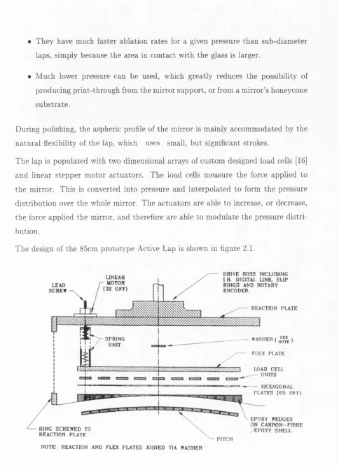
The design of the 85cm prototype Active Lap is shown in flgure 2.1.
DRIVE BOSS INCLUDING I R DIGITAI. LINK. S L IP RIN G S AND ROTARY ENCODER
U N E A R - MOTOR ( 3 2 O F F ) LEAD
SC REW
REACTION PLATE
W A S I I E R ( ^ )
- FI.EX PLATE SP R IN G
UNIT
LOAD CELL UNITS
HEXAGONAL PLATES ( 6 5 OFF) i
EPOXY WEDGES ON C A R B O N - F I B R E
EPOXY S H E L L RING SC RE W E D TO
REACTION PLATE
PITCH NOTE. REACTION AND FLEX PL A T E S JOIN E D VIA WASHER
Figure 2.1: Exploded View of the Active Lap.
At the heart of the lap are two metal discs. The reaction plate is stilf and inflexible,
and provides a reference against which the actuators can push. 32 actuators are
mounted on the reaction plate, and are able influence the flex plate via a spring
unit. The spring unit converts the linear motion of the actuator’s lead screw into
a force applied to the flex plate. The actuators are positioned in three concentric
circles, each containing 8, 8 and 16 actuators respectively. It is a key point to note
th a t the actuators do not bend the flex plate, but modulate the pressure on the
workpiece.
Mounted on top of each actuator is a small microswitch. This is positioned so th a t
when the actuator lead screw is moved as far as is allowable upwards, the switch is
ju st closed.
The actuators are only able to move a certain distance in either direction before they
stall. This distance, d, is known. To position a microswitch, its associated actuator
is set to its null position, where it is exerting no net force onto the flex plate. The
actuator lead screw is then moved upwards by the distance d, and the microswitch
positioned so th a t it it just closed. [10] The actuator positions are then always
measured in relation to the microswitch, e.g. When the actuators are reset, they
are moved to the aforementioned null position by driving the lead screw upwards
until it reaches the microswitch, then downwards the number of pulses equivalent
to the distance d.
The reaction and flex plates are joined via a central washer, which acts as a spacer
to keep the plates separate, and eliminates lateral movements of the plates relative
to each other.
The flex plate is considerably thinner (6mm) than the reaction plate (15mm). It
smooths the force functions exerted by each of the actuators, to a continuous func
tion. Simultaneously, it has been carefully FE modelled to be able to filter out high
spatial frequencies th at may introduce ripples into the mirror surface. [16] The flex
plate is also the medium th a t introduces cross-talk not only between the actuators
and the load cells, but between the actuators themselves. This gives rise to the
coupling coefficients th a t quantify the degree of cross-talk, which are mentioned in
61 load cell attachm ents are mounted in a hexagonal pattern directly onto the flex
plate. Of these, 22 are populated with strain gauges, with the remaining 39 left
unpopulated, being referred to as “dummy” load cells. Each load cell is covered by
a thin hexagonal plate. The hexagons are linked by silicon cement. This effectively
seals the load cells away from any possible contamination, whilst the silicon cement
being highly compliant, ensures th a t one load cell will not piston the next, and
disturb it ’s response.
Beneath the hexagons is a grid of small epoxy wedges th a t match the hexagon’s
flat geometry to the curve of the carbon fibre reinforced epoxy shell. This shell is
cast using the generated mirror profile as a mould, and is used as the mount for the
pitch facets th at do the polishing. As is consistent with normal polishing practices,
the pattern of the pitch facets are off centred with respect to the lap, and therefore
the load cell and the actuator geometries. This is a standard practice th a t helps to
avoid the formation of concentric rings on the mirror surface.
The edge of the carbon fibre shell is attached to a metal ring th a t is screwed to the re
action plate. This serves two purposes. Firstly it means th a t lateral forces generated
by friction are transm itted to the reaction plate, and are therefore not transm itted
to the load cells. This is im portant because the load cell’s design precludes their be
ing subject to lateral forces. [16] Secondly, the ring completely encases the whole of
the delicate part of the lap, which means it should be safer from accidental damage
or contamination.
The drive boss on the top of the lap is attached to two polishing arms, the other
end of which are attached to two off-centred cams. These rotate at slightly different
speeds, driving the lap in a pseudo random path. A load cell is positioned in each
of the polishing arms, which can be combined to measure the total force with which
the lap is driven. This means th at the total frictional force can be calculated. This is
used as another param eter in the ablation algorithm, and gives the user a measure of
the quantity, and the condition, of the polishing slurry th a t is present. As polishing
progresses, the slurry becomes drier as water both evaporates and is driven out from
under the lap. As this happens, the total frictional force increases, and can become
a useful warning, as the lap can literally stick to the mirror if the slurry dries out
A c t i v e LCD 3 o d y
_»-A/WWlV-o ‘b^^W W W V O
-P o w e r G l o b a l j' acK _ o o a
t e e l :licai
n n o
3 P o i n t C a b l e i lev Fi a t D o n u t
\ ' R o t a r y P l a t f o r m R o t a r y \ ' / P l a t f o r m
Ball B e a r i n g s Le g
A c t i v e _c; C l o D c : ~c C o n t r o l l e r
---f---rc
O O D - o ^
C o n t r o l S o f t w a r e .-ew ::'om L ü c e
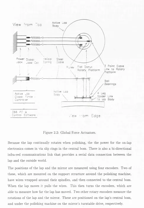
Figure 2.2: Global Force Actuators.
Because the lap continually rotates when polishing, the the power for the on-lap
electronics comes in via slip rings in the central boss. There is also a bi-directional
infra-red communications link that provides a serial data connection between the
lap and the outside world.
The positions of the lap and the mirror are measured using four encoders. Two of
these, which are mounted on the support structure around the polishing machine,
have wires wrapped around their spindles, and then connected to the central boss.
When the lap moves it pulls the wires. This then turns the encoders, which are
able to measure how far the lap has moved. Two other rotary encoders measure the
rotations of the lap and the mirror. These are positioned on the lap’s central boss,
As shown in figure 2.2 there is a ring on the upper side of the lap th a t is constrained so
th a t it does not rotate with the lap. To this are attached three global force actuators.
These provide further control over the pressure distribution on the mirror. They
can pull on the ring to vary the absolute overall polishing pressure, or to tilt the
pressure distribution, effectively rocking the lap.
The lap, the global force actuators, and the encoders, are all controlled by the host
66MHz 486 IBM-PC. As well as providing the user interface, graphical maps, and
d ata storage, this communicates via the infra-red link with an z960 micro computer
th a t is mounted on the top of the lap. This controls the reading of the load cells
and the actuator movements.
Above the epoxy wedges, the whole lap is plane parallel. This means th a t it is
readily adaptable to be able to work on other mirror profiles. A new carbon fibre
shell has to be cast to the correct shape, and the correct epoxy wedges milled, but
once these are in place the rest of the lap remains as it is.
One problem with this design of the Active Lap is th a t the physical thicknesses of
the hexagons, and of the load cells, are all slightly different. This is an inevitable
consequence of their manufacture. However, this means th a t if, for example, one
load cell/hexagon pair was slightly withdrawn compared to the adjacent ones, it will
not be in contact with the epoxy wedges. This loss of internal contact will result in
this load cell never recording a force, i.e. The lap will not be correctly reading the
forces exerted on the mirror.
To attem pt to solve this an epoxy hag was placed between the epoxy wedges and
the hexagons. This consisted of two sheets of plastic th a t were sealed around their
edges, and filled with epoxy glue. The amount of glue was carefully measured so
th a t it would not spill out of the bag and damage the insides of the lap.
When the lap was reassembled, the idea was th at the epoxy glue would fiow whilst
wet, and take up any small spaces between the wedges and the hexagons. This
would mean th a t when it set, it would provide to tal internal contact. As described
in section 4.2.1.1, this proved to be unsuccessful, and was replaced when the lap’s
design was modified.
2.3
M odifications to the Initial D esign
As d etailed in section 4.2.1.1 it was found th a t the lap as described above was not
w orking satisfactorily. Forces on th e pitch were n o t being pro p ag ated th ro u g h to
th e load cells properly. It seemed likely th a t the epoxy bag was n o t successful in
providing to ta l internal co ntact between the hexagons and th e epoxy wedges. It was
also th o u g h t th a t th e lap was not com pliant enough to conform to th e m ism atch
betw een th e lap and the m irror, when the lap was offset.
T he lap, therefore, needed to be modified to rectify these faults. T he to p half of the
lap from th e hexagons upw ards was retained in its entirety, b u t ev eryth in g 1>elow
th e hexagons was replaced.
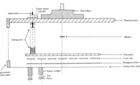
T he new lap is shown in figure 2.4.
T here is a ru b b er sheet, approxim ately 5mm thick, directly below th e hexagons. B ut
as opposed to the epoxy bag which sim ply rested inside the lap, th is ru b b e r sheet
is not only glued to the hexagons, it is also glued to th e flat carbon fibre m em brane
which is directly b eneath it. This m eans th a t intern al co n tact is g u aran teed . In
Linear m otor
(32 off) D riv e B oss L ead screw
R eaction p la te
W asher Sp rin g un it
F lex p la te Load cells H exagonal p lates C arbon fibre shell E p oxy w edges
R in g screw ed
to reaction p late — L_4_ T ile C S S * - Pitch
Figure 2.4: Exploded View of the Modified Active Lap.
addition, the rubber sheet is very much more compliant than the epoxy bag.
The carbon fibre membrane is much thinner than before, which means it will bend
easier. Also, its flat geometry will be much more compliant than previously, since
its former hyperbolic shape would necessarily have introduced a certain amount of
rigidity into its structure.
Below the carbon fibre membrane are epoxy wedges, which take up the spacing
between the flat membrane and the hyperbolic mirror. Onto the epoxy wedges are
stuck pieces of tile, then the pitch facets. The tile is there simply because the pitch
would not adhere to the epoxy wedges.
Another major difference with the new lap, is the distribution of the epoxy wedges
and pitch facets. Before, these were not in vertical alignment with each other, or
with the load cells. This means th a t the load cells would not be measuring the forces
applied to the mirror directly. Instead, the forces would be redistributed as they
were propagated upwards.
one was vertically beneath a load cell. This means th a t the load cells should have a
much more direct measurement of the forces th a t are actually applied to the mirror.
However, this introduced a further complication. The load cells are arranged in
a hexagonal pattern, with one of them being exactly at the centre of the lap. If
the epoxy wedges/pitch facets were placed directly below each load cell, they would
obviously be positioned on a regular grid with a pitch facet at the centre of the
lap. However, this is a well known recipe for polishing concentric rings onto the
m irror surface. The solution to this was to have the area of the pitch facet half
th a t of the load cells. The epoxy wedge/pitch facets could then be offset from the
centre of the lap by half a load cell (approx. 8cm), and still be completely within
a load cell’s footprint, thereby maintaining the direct one-to-one relationship. This
offsetting caused three of the pitch facets to be repositioned so they would be partly
overhanging the edge of the mirror when the lap was being pressed. This is clearly
impractical, so these were removed and three load cells deactivated, leaving a to tal
of 19 active load cells.
As dem onstrated in section 4.2.1.1, this modified design for the Active Lap proved
to be much better than the original. Forces from the mirror are being correctly
propagated to the load cells, and the lap is compliant enough to detect the mismatch
C h a p ter 3
D e sc r ip tio n o f A c tiv e Lap D a ta
A q u isitio n and C on trol Softw are
This chapter describes the software th at has been written to run on the IBM com
patible PC. The purposes of this software are threefold. [17]
• To acquire and store data from several sources, include d ata from the «960
processor th a t controls the electronics on the lap.
• To relate this data to the user in a suitable manner, to allow its’ interpretation
in terms of the actual polishing of the mirror.
• To provide an ergonomic interface between the user and the lap, to facilitate
easy control of all the different software and hardware functions.
A schematic of the overall structure of the Active Lap data aquisition and control
Has a Key Been Pressed? Yes No To Next Page Perform Command Start Change Colour LUTs Move Actuator(s) From Next Page Move/Set
Global Force Actuators
Perform Coordinate Transformation
Update Actuators Interpolate Pressure Distribution Analyse Command Line Options Actuator Control Reset Actuator(s) Lead Screw(s) Initialization Calculate Velocity Distribution Move Actuator(s) S et Which Graphic
Map to Display Read Data
Program Branches Depending on Selection Display Graphics Calculate Instantaneous and Integrated Ablation Rate Distributions
To Last Page From
Last Page
Test Real-Time Updates Hexagon Calibration
Water-Bag Calibration
Time Series Engineering Tests
Ciean Up
Activate/Deactivate Load Celi(s)
Save/Load Load Ceil Configuration
Finite Element Coefficient Tests Take a Bias Frame
Extract Neural Network Data
Verify Coeffs Linearity Verify Coeffs
are Correct Recaiculate Load
Ceil Coefficients
Exit
Verify that Coeffs are Additive Load Celi
Configuration
3.1
N o te s on P rogram m ing Language U se and
O p tim ization s
It was envisaged at the beginning of the project th a t the speed requirements of the
software would stretch the PC to its limits. Therefore the programming language
chosen needed to produce the most efficient code possible with respect to the cpu
time used, whilst retaining its’ portability and being easily maintainable.
Several alternative languages were considered, including BASIC, FORTRAN, pascal,
C, C + + and assembly language.
The last of these was rejected because although it would produce the most efficient
code, its complete lack of portability and difficult maintenance made it unsuitable
for our purposes.
Of the others it was decided th a t C was the appropriate choice. This was because
C is a relatively low level, general purpose language. It combines the advantages of
control structure and portability found in the other high level languages, with the
ability to deal with ‘machine level’ objects such as characters, addresses, pointers
and bitfields. These can be manipulated by the arithm etical and logical opera
tors implemented by the cpu hardware, making C a relatively efficient language to
use. [11] [15] [24]
The other languages also have their strong points, e.g. FORTRAN’S better facili
ties (i.e. simpler syntax ) for manipulating multi-dimensional arrays and dynamic
declaration of array size [24], but the most im portant underlying consideration was
to produce the fastest executing code. C + + was rejected because its run time over
heads would use up valuable cpu time, for which its object orientated facilities were
judged be insufficient compensation.
In order to preserve these advantages of programming in C, the software was w ritten
to conform to the Starlink C Programming Standard. [24] This consists of a number
of suggestions made with maintainability, portability and efficiency in mind.
Despite all the above considerations, it was found th a t the software was nearly
always taking longer than required, (i.e. The control loop was running significantly
be a continual process of optimizing the code with respect to the cpu time used.
In an effort to maximize the efficiency of the code, three principles in particular were
implemented wherever possible.
• When appropriate, calculations were performed using pre-computed look-up-
tables (LUTs). It involves much less cpu time to access the values in a memory
location than to perform the calculations in real-time.
• When the above was not possible, calculations were performed using integer
arithmetic, since this executes considerably quicker than floating point calcu
lations. Loss of precision was minimized by scaling up all the terms in the
calculation.
• The interpolation algorithm was manipulated so as to be expressed in the form
of a simple series, e.g. If the interpolated pressure, P , at an arbitrary point
i is a function of n load cell readings, L, then this function was rewritten to
give
= (3.1)
j=i
where Cij, the interpolation coefficients, usually had a considerably more com
plex algebraic form than the original function. These coefficients were then
only calculated once, during the software initialization, and stored in memory.
This meant th a t during each control cycle the interpolation required for each
point involved only the simple calculation shown in equation 3.1.
It was still found, however, th a t the most cpu intensive routines, namely interpo
lating the pressure between the load cells and writing the graphical display to the
com puter screen, were not executing as quickly as required. This was because al
though C is efficient relative to other high level languages, compilers are not yet
sufficiently intelligent to produce the most efficient code possible. A significant de
crease in execution time of these routines was achieved by rewriting and manually
optimizing them in assembly language. This meant the loss of portability, but the
increased speed of execution was a more im portant consideration. Also, since as
sembly language is much more difficult to maintain than C, a considerable effort
3.2
U ser Interface
3.2.1
D O S v s W in dow s
The first consideration when designing the user interface was whether to run the soft
ware under DOS or under Windows. The latter would mean th a t advantage could be
taken of the Graphical User Interface (GUI) available when using the Windows envi
ronment. This would mean th at the user could use a standard, well-written interface
w ithout having to learn a new system. It would also have saved the programmer
time in constructing a new interface from scratch. Unfortunately Windows imposes
overheads on the system and will cause the software to run slower. [35] W hether this
would be significant or not is almost impossible to predetermine, so it was therefore
decided to run the software under DOS, although it may be appropriate to review
this decision at a later date.
Note th a t the other advanced features of Windows such as multi-tasking and trans
ferring or linking d ata between different applications were decided to be unim portant
for our purposes.
3 .2 .2 K ey based sy stem vs G U I
It was a m ajor requirement th at the control software provided a well designed,
ergonomic interface for the user. Two possibilities were considered.
• A key based system, where different functions are executed by pressing dif
ferent keys on the computer keyboard, (e.g. Pressing < F 1 > displays the
graphical pressure map, whilst < F 7 > accesses the A ctuator Control menu.)
• A GUI where different functions are executed by selecting the appropriate item
from a graphical menu.
Of these, it was decided th a t implementing either could meet our requirements, so
the former was put into effect simply because it was considered th a t this would
take less programming effort. This operates by using the function keys (<F1-10>)
This proved initially to be very successful, while the number of functions available
to the user was fairly small, but has became somewhat unwieldy as the number
of functions has grown. Therefore it would be appropriate in the future to put
the latter into effect, whereby the user can select options from different menus as
required.
This selection should be carried out either by clicking the mouse on the desired
option, or by pressing the key corresponding to a highlighted letter in the menu
option, (e.g. The Pressure map menu option would have a highlighted letter P,
so could be selected either by clicking the mouse on the option, or by pressing the
< P > key on the keyboard.)
It it thought th a t this GUI design will be much more successful. It should combine
much easier access to all the different functions available with the simplicity of using
the mouse as an input device, whilst retaining the earlier option of making selections
via keypresses.
3.3
M od e S election
In order to allow the user either to record data about the current polishing run, or
to review d ata from a previous polishing run, the software is designed to run with
two separate modes of operation, namely real-time data acquisition mode and demo
mode. The mode required was selected by applying the appropriate command line
option when running the software.
• In real-time data acquisition mode the software reads in all d ata from the
hardware, and then saves it to the hard disk for subsequent analysis. The
graphical displays and calculations are therefore being done on data from the
current polishing run.
• In demo mode the software reads in data stored on the hard disk during a
previous polishing run. Hence the software will be showing a demonstration
3.4
G raphical D isplays
3.4.1 G en eral P ro p erties
A suitable method for relating d ata to the user had to be devised, of which the
simplest method was to display a table of numbers. This was useful to have on
occasion, particularly when the lap was undergoing engineering tests, b ut for more
general use was very difficult to interpret in terms of what was actually happening
to the mirror.
It was therefore decided to have graphical representations of the data. This approach
had proved to be extremely successful in previous OSL projects, particularly for the
control system for the UCL Échelle Spectrograph (UCLES) which was designed and
built by the OSL for the Anglo-Australian Observatory. [22]
There were two distinct types of d ata which were displayed in different ways.
• Values of a param eter th a t is distributed over the whole mirror (e.g. pressure,
velocity) are represented by a graphics map showing the mirror as a circle
on the screen which is filled with pixels of different colours. Each colour
represents a different range of numerical values of the param eter at th a t point
on the mirror, (e.g. red might represent a large value of the data, green an
intermediate value and blue a low value.)
The relationship between the colour levels and the d a ta values are given by
the colour look-up-tables (LUTs), described in section 3.4.1.2.
• Values of a single param eter (e.g. a load cell reading the force exerted by a
global force actuator) are displayed as ‘thermometer bars’, where as the numer
ical value of the param eter increases, the level of the thermom eter increases,
and vice versa.
Several different displays were available for the user, the general properties common
3.4.1.1 Screen Layout
In order to provide easy access to many different pieces of information at once,
the layout of the computer screen was carefully designed so as to avoid becoming
cluttered and confusing. Photographic examples of the computer screen can be seen
in chapter 4.
There were six separate components to each screen, namely
• Title - This showed which display was active and the appropriate units for
the colour LUT.
• Map - This was the graphical display of the param eter currently selected, (e.g.
pressure map, velocity map, etc.)
• Colour LUT - This displayed the range of numerical values corresponding to
each colour level on the display map. The units were displayed in the title.
• Global Force Actuators - This showed the force read by the load cells on the
global force actuators. The values read, along with their sum (i.e. the total
force the lap is lifted by) were displayed as ‘thermometer bars’.
• Total Frictional Force - This was very similar to the global force actuator
display, but showed the force read by the load cells in the polishing arms, also
displayed as ‘thermometer bars’.
• Information - This either showed the mean time per frame (see section 3.9.3),
or, when the user entered a command, this echoed the keyboard and gave error
messages when applicable.
3.4.1.2 Colour LUTs
W ith the PC VGA display th a t was being used for this project, a maximum of 256
different colours levels are available to be displayed on the screen at any one time.
Of these, four have to be permanently assigned to single colours, while the others
ware free to be assigned with different colours when the LUT is altered.