502 | P a g e
PERFORMANCE ANALYSIS OF NON-CIRCULAR
HYDRODYNAMIC JOURNAL BEARING USING CFD
Uddhav Ghadge
1, Prof. A.K. Gangrade
21
M.Tech Student,
2Faculty,
Mechanical Engineering Department,
K J Somaiya College of Engineering, Vidyavihar (E), Mumbai,( India)
ABSTRACT
In high speed machine to improve the shaft stability and reduced power losses non-circular bearings are used
extensively. Performance of non-circular bearings depends on operational and geometrical parameters such as
offset factor and speed. In this present paper the CFD software has been used for analysis of non-circular
hydrodynamic journal bearing. The Geometrical model and meshing has been prepared in GAMBIT and
simulated by using ANSYS fluent software. It has been observed from the investigation that journal rotational
speed and offset factor influence the maximum pressure generated in the clearance space of the bearing.
Keyword: CFD,Non circular hydrodynamic journal bearing, Offset factor, Speed
I. INTRODUCTION
Application of various type of noncircular journal bearing has increased in recent years. The noncircular journal
bearings such as lobed and offset journal bearing provide better performance than circular hydrodynamic journal
bearing. Plain circular journal bearings operate with only a single active oil film which results in high rise in
Pressure and temperature. This is eliminated in noncircular hydrodynamic bearing as they operate with more
than one active fluid film. These bearings also possess superior stiffness, damping and reduced temperature in
oil film as compared to circular hydrodynamic journal bearing. Non-circular hydrodynamic journal bearings
improve journal stability, decrease power losses and increase oil flow.This bearings are used in steam turbines,
steam generators, gear boxes, connecting turbine. Amit Chauhan et al. [1] analysed offset-halves and elliptical
bearings using different oils. They observed that the temperature rise in lower lobe is higher compared to upper
lobe. Mahesh Aher et al. [2] presented the Pressure Distribution Analysis of Plain Journal Bearing with Lobe.
They compare the pressure distribution and load carrying capacity of bearing at different speed.
Amit Chauhan et al. [3] analysed thermal effects in elliptical journal and lobed bearings.They conclude that the
temperature rise in lower lobe of the elliptical bearing was higher than the upper lobe in every case. A.D.
Rahmatabadi et al [4] analysed Micropolar lubricant effects on the performance of noncircular lobed bearings.
They investigated effects of the coupling number and size of material characteristic length on the static
performance of bearing. . Taylor et al. [5] performed the experimental investigation of thermal effect in circular
and elliptical plain journal bearing. R. Sinhasan et al. [6] has studied the analysis of two-lobe porous
hydrodynamic journal bearings. They conclude that porosity has important role for both static and dynamic
characteristics of two-lobe porous hydrodynamic journal bearings. Mehta et al. [7] has been presented two lobe
503 | P a g e
load bearing capacity. Gregory Patella [8] analysed pressure distribution in bearings of various profiles viz.
Elliptical, offset-halves and circular bearings.They observed that circular journal bearings are subjected to oil
whirl at increased rotational speeds, hence, elliptical and offset-halves bearings are used. Dinesh Dhande et al.
[9] analysed circular journal bearing for static pressure distribution, stress in bearing and deformation in bearing
using fluid structure interaction. The results obtained in this paper were used to compare the contour plot and
static pressure values of circular bearing and thus validate the results obtained for elliptical bearings in this
paper.
In the present paper the analysis of pressure distribution in the fluid film has been done using CFD software.The
bearings has been modelled and meshed in Gambit and then imported into Ansys Fluent. The offset factors
considered were 0.8, 0.9, 1.1, 1.2 and rotational speeds of journals were 1000 rpm, 2000 rpm and 3000 rpm. The
results are validated by obtaining contour plot for static pressure distribution in circular hydrodynamic journal
bearings corresponding to the same journal speeds and compare with available data.
II. ANALYSIS
When analysis of a bearing was done using Reynolds Equation, Reynolds equation governs the pressure
distribution around the circumference of journal in the clearance space of fluid film bearing. It is used to plot the
Pressure profile in the hydrodynamic fluid film theory.The coordinate system and the geometry of fluid film
journal bearing is shown in Fig. 1. An equilibrium position under the external load is attended due to the
hydrodynamic pressure generated by the lubricant film through journal rotates with an angular velocity ω.
dx
dh
U
z
p
h
z
x
p
h
x
(
3
)
(
3
)
6
(1)The assumption of the noncircular hydrodynamic journal bearingas it is rigid aligned bearing with steady state
condition. The flow is Newtonian, isothermal, inviscous, incompressible and no inertia effect. Both Journal and bearing surfaces are smooth and a constant vertical load is only to be applied at journal centre. Lubricant
pressure distribution as a function of journal speed, bearing geometry, clearance and lubricant viscosity is
described by Reynolds equation.
The objectives of present work as follows:
1. To analyse the variation in pressure distribution in the oil film for various offset factors and rotation speeds
of journal.
2. To compare the results of static pressure distribution in elliptical bearing with that ofcircular bearing.
III. METHODOLOGY
In order to analyse pressure distribution in the bearings using ANSYS Fluent software, meshing was done using
Gambit. Gambit is pre-processor software used for engineering analysis. Edge meshing was carried out with
interval count as 30 along the length and elliptical and circular profile. Face meshing and volume meshing
504 | P a g e
Fig.1Geometry and Mesh model of Non circular hydrodynamic journal bearing With offset factor =0.8
The mesh file imported into ANSYS Fluent to obtain the pressure contour plots. The bearing wall was
considered as stationary and the journal was modelled as moving wall. The sides of the lubricant volume had
been assigned with a zero pressure condition for lubricant to flow freely. The sides of the bearing were assigned
pressure inlet and pressure outlet. The temperature of each of the entities i.e. bearing, journal, pressure inlet and
outlet were taken as 40°C. The journal was given a rotational speed in rpm. At the pressure outlet, the pressure
distribution was assumed to be radial.The solution scheme was taken as SIMPLE. The spatial discretization of
pressure was taken as PRESTO.Standard initialization was used and was computed from the inner most layer
i.e. the journal.
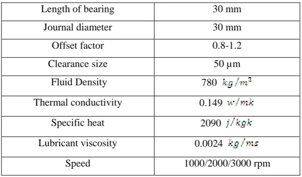
Table 1Geometrical and operational parameter of non circular journal bearing
Length of bearing 30 mm
Journal diameter 30 mm
Offset factor 0.8-1.2
Clearance size 50 µm
Fluid Density 780
Thermal conductivity 0.149
Specific heat 2090
Lubricant viscosity 0.0024
Speed 1000/2000/3000 rpm
IV. RESULT AND DISCUSSION
The contour plots for noncircular hydrodynamic journal bearing with the offset factors (0.8 to 1.2) and rotational
speeds of journal (1000, 2000 and 3000 rpm) areillustrated below. The pressure values are measured in Pascals
(Pa).Results have been observed from the investigation that offset factor influence the maximum pressure
generated in the clearance space of the bearing.It is observed from the static pressure contour plots that there are
505 | P a g e
(a) N=1000rpm (b) N=2000rpm (c) N=3000rpm
Fig.2:
Pressure contour of circular hydrodynamic journal bearing(offset factor =1) with eccentricity ratio = 0.1(a) N=1000rpm (b) N=2000 rpm (c) N=3000rpm
Fig.3:
Pressure contour of noncircular hydrodynamic journal bearing with offset factor = 0.8(a) N=1000rpm (b) N=2000rpm (c) N=3000rpm
Fig.4:
Pressure contour of noncircular hydrodynamic journal bearingwith offset factor =0.9(a) N=1000rpm (b) N=2000rpm (c) N=3000rpm
506 | P a g e
(a) N=1000rpm (b) N=2000rpm (c) N=3000rpm
Fig.6:
Pressure contour of noncircular hydrodynamic journal bearingwith offset factor =1.2The above method and results are validated by comparing the nature of static pressure contour plot of circular
bearing.It can be observed that there are two pairs of maximum and minimum static pressure areas that are
generated. The point where the area with maximum and minimum pressure will be generated is influenced by
the offset factor. It can be observed from the contour plots of circular journal bearing that the two pressure areas
lie on opposite sides of the profile. One of the areas exhibits maximum static pressure and on the side opposite
exist an area which exhibits the minimum static pressure.These results in larger clearance andelliptical bearings
are also susceptible to oil whip and whirl.Ideal operating conditions for any bearing refers to isothermal
conditions. In actual operation there are changes in temperature while operation. Isothermal conditions do not
prevail in actual operation of a bearing. If we consider a circular bearing, due to this change in temperature the
profile of the bearing will again be changed, thus getting converted into a non-circular bearing. The heating due
to temperature rise will cause a change in profile of the bearing.
The graph for the maximum pressure generated v/s offset factor for the three journal speeds was plotted and
graph for maximum pressure generated v/s journal speed for various offset factors was also plotted.
Fig.7
Maximum pressure generated v/s offset factor plot for Non circular hydrodynamic journal bearing withvarious Speed, Kerosene as a lubricant
It can be observed from the above graph that as the journal speed increases, for the same offset factor, values of
maximum pressure generated increases. The maximum pressure generated in circular bearing is less than
507 | P a g e
Fig.8
Maximum pressure generated v/s journal speed Of Non circular hydrodynamic journal bearing withdifferent offset factor
As observed in the graph, the range of maximum pressure generated in the bearing with offset factor = 0.8 is the
highest and the range of maximum pressure generated in the bearing with offset factor = 1.2 is the lowes
t.
Themaximum pressure generated in circular bearing is less than maximum pressure generated in the bearing with
offset factor = 0.8
V. CONCLUSION
The point where the area with maximum and minimum pressure will be generated is influenced by the offset
factor. From the contour plots of elliptical bearing it is observed that for offset factors more than 1 i.e. 1.1, 1.2,
the area exhibiting maximum pressure concentration lies on the opposite side of the profile when compared to
bearings with offset factor less than 1 i.e. 0.8, 0.9. The maximum pressure generated in circular bearing is less
than maximum pressure generated in the bearing with offset factor = 0.8. As observed in the graph 2, the range
of maximum pressure generated in the bearing with offset factor = 0.8 is the highest and the range of maximum
pressure generated in the bearing with offset factor = 1.2 is the lowest.
REFERENCES
[1] Amit ChauhanandRakesh Sehgal,“Thermal Studies of Non Circular HydrodynamicJournal
Bearing,Profiles: Offset – Halves and Elliptical” in InTech Journal, 2012.
[2] Mahesh Aher, Sanjay Belkar, R. R. Kharde, “Pressure Distribution Analysis of Plain Journal Bearing with Lobe Journal Bearing” , International Journal of Engineering Research & Technology (IJERT) Vol. 2,
January- 2013
[3] Rakesh Sehgal, Amit Chauhan and Rajesh Kumar Sharma, “An Experiment Investigation of Oil Film
Temperatures in Elliptical Profile Journal Bearing” ,International Tribology , Hiroshima, 2011.
[4] A.D. Rahmatabadi ,M. Nekoeimehr,R.Rashidi , “Micropolar lubricant effects on the performance of
noncircularlobedbearings”,InternationalTribology43,2010,pp.404413
[5] M.T. Ma, C.M. Taylor, “Experimental investigation of thermal effect in circular and Elliptical plain journal
bearing”, Tribology International,Volume29,1996.
[6] R.Sinhasan ,M .Malik and Mahesh Chandra, “Analysis of two-lobe porous hydro dynamic journal
508 | P a g e
[7] N. P. Mehta, S. S. Rattan and Rajiv Verma, “Stability Analysis of Two Lobe Hydrodynamic Journal
Bearing using Couple Stress Lubricant” in Journal of Engineering and Applied Sciences, Vol. 5, January
2010.
[8] Gregory Patella, “Studies of Eccentricity and Pressure on Selected Journal Bearings”,December 9th, 2013.
[9] Dinesh Dhande, Dr. D. W. Pande, Vikas Chatarkar, “Analysis of Hydrodynamic JournalBearing Using
Fluid Structure Interaction Approach”, Volume 4, Issue 8, August 2013.