767 |
P a g e
A 16 CORE PROCESSOR WITH HYBRID
INTER-CORE COMMUNICATION
K.Ravikanth Reddy
1, G.Gouthami
2 1,2Asst.Professor, Dept.of.ECE, GRIET,Hyd
I. INTRODUCTION
In order to satisfy performance needs single core styles were pushed to higher clock speeds, thereby the facility
demand grew at a quicker rate than the frequency. This power downside was exacerbated by styles that tried to
dynamically additionalct extra performance from the instruction stream, As we'll note later that this crystal
rectifier to styles that were advanced, unmanageable, and power hungry. to satisfy these needs chip designers
turned to multi-core processors. A multi-core processor is one that consists of multiple range of processors on
one chip, of these processors add parallel thereby the performance of the multi-core processor will increase. to
satisfy power budget several efforts square measure taken to optimise memory hierarchy and to extend
similarity at the same time.
Inter-core communication plays a crucial role to balance the facility and performance in a very multi-core
processor. currently a day‟s multi-core design introduces new challenges for effective implementation of
inter-core communication. once bound downside is given to Associate in Nursing embedded processor the turnout
depends on each computing capability and communication potency between cores. to reinforce computing
capability there square measure varied technologies like terribly long instruction word
(VLIW), Single instruction multiple knowledge (SIMD), Super scalar, Reduced Instruction set pc (RISC) etc.
however there are not any matured solutions for inter-core communication, therefore the analysis specialize in
up the potency of inter-core communication.
Shared-memory communication is most frequently used inter-core communication mechanism owing to its easy
programming model however it fails to supply ample quantifiability with the increasing range of
processors.[3]-[5]. so the designers turned to message-passing communication mechanism that has high quantifiability even
with the rise in range of resources.[6]-[9]. we will acquire high performance by group action each the inter-core
communication mechanisms.[1]. The planned system introduces a replacement variety of inter-core
communication known as Memory- toMemory communication through that the trail from supply to destination
in multiple range of clusters gets reduced thereby the performance gets will increase alot compared to previous
mechanisms.
This paper is unionized as below. Section II describes the key options of the 16-core processor. Section III
details the look and implementation of existing ways. Section IV describes the implementing technique. Section
V presents the measured results. Section VI concludes the paper. Section VII describes the long run work.
II. KEY FEATURES
768 |
P a g e
A processor is associate degree electronic component executes a group of directions every at a time and
produces results. A multi-core processor may be a single computing element with 2 or a lot of freelance actual
processors (called "cores"), that ar the units that scan and execute a group of directions at the same time.
Multi-core processor design is currently turning into the thought of economic processor design within the market.
correspondence and pipelining ar enforced during a multicore processor. Thereby the performance of the
multi-core processor is incredibly high in comparison to a standard processor. To execute associate degree instruction
the processor can take the information either from the shared-memory or from another processor.
B. Inter-core Communication.
It is outlined because the communication between multiple variety of processors integrated on one chip. Power
and price budgets limits high computability processors to be integrated on a chip thereby the general
performance of multi-core processor depends extremely on intercore communication. In multi-core processors
the information stream flows through many processor cores till obtaining the results. so the output is very
relevant to intercore communication. With the increasing variety of cores a lot of challenges ar needed to realize
economical intercore communication.
C. Hybrid Inter-core Communication.
Two sorts of inter-core communication mechanisms exist for associate degree embedded processor. the primary
one is Shared-memory communication that is enforced by creating use of a shared cache or memory units.
Typical examples ar cortexA9, UltraSPARC, HYDRA etc. The options of shared-memory communication ar
straightforward programming, used for transferring of enormous blocks of information. It faces many challenges
that limits its use in future processors. 1st its low measurability, quite eight cores aren't allowed to share one
memory. In associate degree eight core processor the interconnections take space such as 3cores and consume
power such as one core. Second cache coherence problems ar terribly complicated which ends in additional
hardware overhead. owing to its high measurability the second variety of communication i.e., Message-passing
communication attracts several designers. it's enforced by connecting the processors during a Network in sure
topology like mesh, bus, ring etc. Typical examples ar ASAP, Intel-80 tile etc. In spite of its sturdy
measurability it's complicated programming model, and also the quality of service (QoS) isn't warranted.
Shared-memory and Message-passing communications ar appropriate for 2 completely different environments.
By combining each the mechanisms it's appropriate to figure all told situations. Shared memory communication
is enforced by a cluster based mostly memory hierarchy and Message-passing communication is enforced by
transcription the processors during a second mesh network on chip. The options of shared-memory
communication and message-passing communication ar delineate below in Table-1.
D. Cluster-Based Memory Hierarchy.
In multi-core processors the competition for memory resources will increase with increasing core variety ends
up in “Memory wall” problems, operation latency and cache coherence problems become a lot of
complicated.chip digital computer. Some designers solve this downside by exploitation cache free architectures
and a few others instructed to partition the cache in to shared and personal memory so as to boost the potency.
E. Direct operation.
Direct operation (DMA) is {one of|one among|one {in a|during a|in associate degree exceedingly|in a very}ll|one
769 |
P a g e
between an input/output (I/O) device and also the core process unit or memory in a pc. DMA is one amongst the
quicker sorts of synchronization mechanisms, typically providing vital improvement in terms of each latency
and output. DMA permits the I/O device to access the memory directly, while not exploitation the core. DMA
will result in a big improvement in performance as a result of knowledge movement is one amongst the
foremost common operations performed in process applications.
III. EXISTING METHODS.
The existing system has sixteen-core processors that ar connected in 3× six second Mesh intelligence agent kind
that links 16 core processor (PCore) and a couple of memory cores (MCore). Cluster-based design is used with 2
clusters wherever every cluster contains eight PCores and one MCore. The PCores gift within the cluster will
ready to access the MCore gift within the same cluster. A hybrid inter-core communication theme is used
supporting each shared-memory and message-passing communications. Shared memory in MCore permits
shared-memory communications inside the cluster, and therefore the intelligence agent permits message-passing
communication among
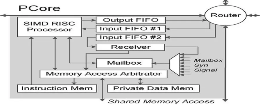
all PCores. The design summary of existing system is as shown in Fig.1 information enters and leaves the
processor through the input and output FIFO ( 1st In 1st Out). every PCore has 2k-word instruction memory and
1k-word personal information memory. MCore has 8k-word shared memory with four memory banks.
A. planning of key modules
1). Processor core: The design of PCore is shown in Fig. 2. The processor core has six-stage pipelined SIMD
770 |
P a g e
counter. The rewrite stage converts the directions fetched into opcodes and fetches operands from register files.
Operations like addition, subtraction, multiplication, and, or, etc. All arithmetic and logical operations ar
performed and address calculations ar wiped out execution part. information memory accessing is finished in
memory stage. the information is aligned in align stage and written back to register file or output FIFO in write
back stage. The sixstage pipelining of the processor is as shown in Fig.3. generally personal information
operation needs one clock cycle and shared operation takes a pair of clock cycles owing to its competition.
SIMD Instruction Set design (ISA) supports three computing modes includes scalar-scalar, scalarvector and
vector- vector. currently a day‟s most of the
processors support 3 types of information widths they're 8b, 16b, and 32b. The projected processor is of 32b
wide. we have a tendency to reconstruct {the information|the info|the information} path with reconfigurable data
dimension. Power consumption reduces with the rise in information vicinity therefore, we have a tendency to
extended the register file size to sixty four words from thirty two words. the advantages of this extended register
file ar a lot of range of registers is offered means that a lot of capability to assign information that the
performance of the processor gets improved. These register files is FIFO mapping ports. As we have a tendency
to ar directly process with the registers therefore, no want of load/store directions thereby the time to access the
information from memory gets reduced. every core processor features a router that consists of four FIFOs and a
sway unit to manage the flow mechanism.
771 |
P a g e
Fig. 3. The six-stage pipelining of the processor core.
2) Memory Core:
A MCore consists of 8k-word shared memory that is divided in to four banks. All processor cores will access
the MCore directly by hardwires with mounted priority order to get high performance and low price, and to alter
the arbitration logic and optimize the vital path. owing to mounted priority access it should ends up in live-lock
conditions, however really the live-lock isn't observed. The shared memory is especially wont to map the
information between totally different processors. If the information isn't prepared within the memory the PCore
needs to wait until the information is offered even supposing it's having highest priority. The latency of MCore
accessing while not competition is a pair of cycles. It will increase if multiple range of processors requests the
memory at identical time as a result of the processors with low priority needs to wait until it gets its flip
The design summary of MCore is as shown in Fig. 4. it's a electronic device that is employed to pick out the
processor which will access the MCore, And a Decoder is gift that is employed to pick out the memory bank on
that the processor will store or load the info. A router is meant that performs an equivalent operations as in
PCore. B. style of Hybrid Inter-Core Communications. A hybrid inter-core communication is used by group
action each message-passing and shared-memory communication schemes that is enforced in Fig. 5. The 2nd
Mesh operative supports the message-passing communication that is very ascendable and is appropriate for
transferring of frequent and scattered information packets. it's chiefly utilized in management information flow
applications. The shared memory within the MCore supports the shared-memory communication within the
cluster that is appropriate for large information block transferring. it's chiefly utilized in machine dataflow
applications.
1) Shared-Memory Communication:
The processors that square measure gift within the same cluster will access the MCore with fastened priority
order. The scoop range of PCores during a cluster square measure restricted to eight. The processor on the
highest left corner has highest priority and also the PCore on the lowest right corner has lowest priority. High
inter-core synchronization potency has been achieved through hardware-aided mailbox mechanism.
Shared-Memory communication involves chiefly 3 steps, 1st the supply PCore stores the info in to shared memory, next
772 |
P a g e
shared memory once the synchronization signal is received. The steps for sharedmemory communication square
measure as shown in Fig. 6.
Fig.5.Architecture overview of MCore
Fig.6. Implementation of the hybrid inter-core communications:
(a)Sharedmemory via MCore (b)Messagepassing via NoC
Fig.7. Three steps in a typical shared-memory communication: (1) Src PCore stores
data to shared memory in MCore; (2) Src PCore sends synchronization signal to Dest
PCore; (3) Dest PCore loads data from shared memory when synchronization signal is
773 |
P a g e
2) Message-Passing Communication:
A 3×6 2nd Mesh operative supports Message-Passing communication wherever associate degree sex
chromosome dimension ordered hole routing rule is enforced. Even the shared-memory communication is
enforced solely among the cluster, The Message-passing communication is enforced between any 2 processors
within the chip (i.e., with within the cluster or outside the cluster). it's additional ascendable and is especially
used for transferring of frequent and scattered information. excluding its blessings it's a pair of bottlenecks. the
primary one is that the uncertainty within the communication. The network with significant traffic can block the
info packets within the channel thus the latency gets enlarged. however with the help of shared-memory
communication among the cluster the traffic load on the network is reduced. The second bottleneck lies within
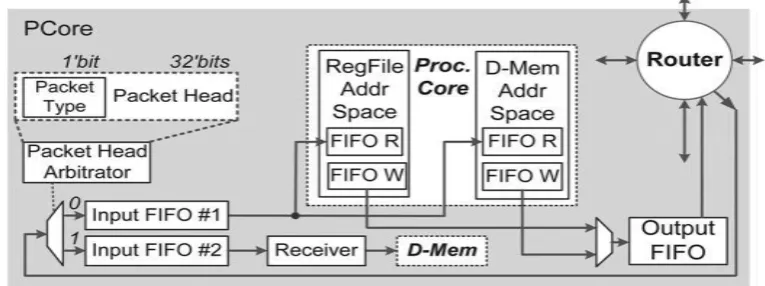
the information transferring between the processor and router. By victimisation 2 input inventory accountings
and one output FIFO between the Processor and router we are able to solve this drawback. One input inventory
accounting is employed to receive {the information|the info|the information} coming back from another
processor core and second inventory accounting is employed to receive data coming back from memory core.
once router receives information from another router supported the savings bank digit {it can|it'll} decide
whether or not the info comes from PCore or from MCore then it will store the info on the corresponding
FIFO‟s. {the information|the info|the information} from one in all the input inventory accounting is captive to
extended register files or information memory and also the information from second input inventory accounting
is captive to the receiver then to data memory. the info path in message-passing communication is as shown in
Fig. 7.
3) Hardware-Aided Mailbox Synchronization:
To support inter-core communication Hardwareaided mailbox synchronization is employed instead of package
synchronization protocols. each core i.e., each PCore and MCore includes a mailbox and it's accessed by PCores
and also the receiver within the same cluster. It generates a synchronization signal supported that the SIMD
processor can settle for the input file. By employing a electronic device we are able to choose {one of|one
among|one during all|one amongst|one in every of} the eight PCores gift in a cluster and a receiver. Mailbox has
nine registers of four bits every that square measure accustomed store the LSB bits of PCores and also the
receiver. By victimisation address associate degreed alter inputs {we can|we can|we square measure able to}
choose one in all the registers and verify its price with the check price if each the values are equal the mailbox
will come back a sound signal otherwise an invalid signal is generated. the planning of the mailbox is as shown
774 |
P a g e
Fig.7. Datapath of the message-passing communication in PCore.
IV. PROPOSED SYSTEM:
The projected system introduces a brand new mechanism for inter-core communication i.e., a
Memoryto-Memory communication between the MCores in 2 clusters. it's enforced by employing a memory interface it
should be a inventory accounting, Router, DMA etc. so as to implement this Memory-to-Memory
communication 1st we've got to style a processor design with sixteen-core processors that ar connected in 3× vi
2nd Mesh intelligence officer that links 16 Fig.8. Hardware style of the mailbox synchronization core processor
(PCore) and a couple of memory cores (MCore). Cluster-based design is used with 2 clusters wherever every
cluster contains eight PCores and one MCore. The PCores gift within the cluster will ready to access the MCore
gift within the same cluster. The coming up with and implementation of processor cores (PCore) and memory
cores (MCore) is explained in existing strategies. This portion primarily concentrates on coming up with the
memory interface and implementing memory-to-memory communication. The Memory interface is also a
inventory accounting, ROUTER, DMA....etc. Here it's a DMA epitome that is especially designed with specific
functionalities. It consists of some memory which can be a register (or) a inventory accounting and it's wont to
store the info loaded from the MCore. A controller is needed to regulate the load store operations within the
memory. the most purpose of this memory interface is transferring the info between 2 memory cores in 2 totally
different clusters directly while not the intervention of processor cores. The memory-to-memory
communication between clusters is enforced merely in 5 steps 1st the info is loaded in to the supply processor
(PCore 1) through associate input inventory accounting. Second the info from supply processor is loaded
directly in to memory core gift within the same cluster. Next by employing a memory interface knowledge|the
info|the information} is loaded in to the interfacing part and this data is transferred from interfacing part to
memory core gift within the second cluster. Next the info from second MCore is directly loaded by destination
Processor core (PCore 16). in conclusion the info from destination processor is collected through associate
output inventory accounting. The design of projected system is as shown in Fig. 8. If we have a tendency to
observe the 3 communication mechanisms the communication path is greatly reduced from cluster to cluster just
775 |
P a g e
parts thence it's terribly economical to use memory to memory communication in multicore processors
compared to shared-memory and message-passing communication.
V. MEASUREMENT AND EVALUATION:
1) Area:
The projected cache-free design will considerably scale back chip space. Moreover, embedded applications
sometimes need restricted memory resources, therefore solely 256 kilobyte on-chip memory units ar enforced.
As a result, we will place additional space budgets on execution cores and inter-core communication units. The
no of LUT slices needed to implement shared-memory, message-passing and memory-to-memory
communication ar 1279, 1466 and 922 severally. Atmost the communication mechanisms consumed solely hr of
total sliced LUTs. the whole details ar as shown in synthesis results.
2) Performance and power:
In multi-core processors the outturn primarily depends on computing capability and communication potency
between cores. to boost computing capability there ar varied technologies like VLIW, SIMD, Super scalar,
RISC etc. so as to attain high communication potency we have a tendency to ar proposing this methodology.
The 3 communication mechanisms during which 2 of them ar already existing schemes and also the last one is
new enforced here. during this paper we have a tendency to ar implementing the 3 communication mechanisms
and so we have a tendency to ar comparison the throughputs of existing strategies with projected one. it's
discovered that the sharedmemory communication takes 610ns to transfer the info from supply processor to
destination processor and Message-passing communication needed 470ns to transfer the info between supply
and destination processor. The projected methodology i.e., memory-to-memory communication needs solely
330ns to transfer the info. thence from these results it's discovered that the projected inter-memory
communication mechanism is incredibly abundant effective and leads to high performance compared to
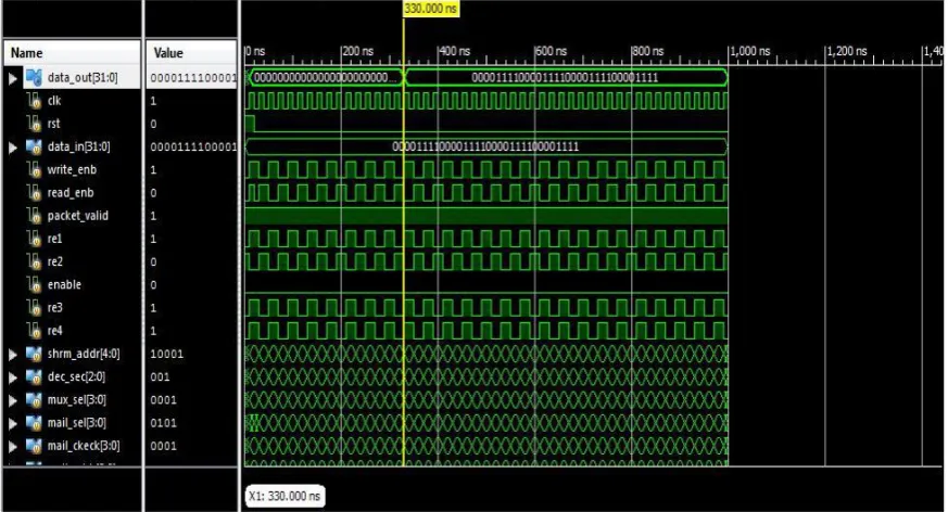
shared-memory and message-passing communication. The simulation results ar as shown in Fig.9, Fig. 10, Fig. 11. 2
cluster-776 |
P a g e
based memory hierarchy, therefore connected hardware overhead is additionally reduced. Second, the info
neighbourhood is improved by extended register file and separation of personal and shared memory.
Fig. 9. Simulation results of shared-memory communication.
777 |
P a g e
Fig. 11. Simulation results of memory-to-memory communication.
VI.CONCLUSION
A 16-core processor for embedded applications with Memory-to-Memory communications is planned during
this paper and it's compared with existing inter-core communication mechanisms. The processor has sixteen
processor cores and a couple of memory cores. Message-passing communications area unit supported by the
3×6 second Mesh intelligence agent, and shared-memory communications area unit supported by shared
memory units within the memory cores. The cluster-based memory hierarchy makes the processor well-suited
for many embedded applications. The processor chip incorporates a total 256 computer memory unit on-chip
memory, whereas every processor core has Associate in Nursing eight computer memory unit instruction
memory and a four computer memory unit personal knowledge memory, and every memory core incorporates a
thirty two computer memory unit shared memory. A memory-to-memory communication is enforced employing
a memory interface referred to as DMA. The DMA used here may be a model one that performs solely specific
functions. The planned system provides high turnout compared to existing ways. The planned system is
enforced in 90nm CMOS victimisation XILINX twelve.2 version computer code.
VII. FUTURE WORK
The performance of the processor gets still hyperbolic by implementing the inter-memory communication with
778 |
P a g e
REFERENCES
[1] Zhiyi Yu, and Ruijin Xiao , ”A 16-Core Processor With Shared-Memory and Message-Passing
Communications.”.Trans.circuit syst.vol.61,No.4,April 2014.
[2] G. Blake, R. G. Dreslinski, and T. “A survey of multicore processors: A review of their common
attributes,” Signal method. Mag., pp. 26–37, Nov. 2009.
[3] R. Kumar, V. Zyuban, and D., “Interconnections in multi-core architecture: Understanding mechanisms,
overheads and scaling,” inProc. 32nd Int. Symp. pc design (ISCA‟05), 2005, pp. 408– 419.
[4] H.-Y., Y.-J. Kim, J.-H. Oh, and L.-S. Kim, “A reconfigurable SIMT processor for mobile ray tracing
with rivalry reduction in shared memory,” Trans. Circuits Syst. I, Reg. Papers, no. 60, pt. 4, pp. 938–
950, Apr. 2013.
[5] L. Hammond, B.-A. Hubbert, M. Siu, M.-K. Prabhu,M. Chen, and K.Olukolun, “The stanford Hydra
CMP,” Micro, vol. 20, no. 2, pp. 71–84, 2000.
[6] A. S. Leon, B. Langley, and L. S. “The UltraSPARC T1 processor: CMT responsibleness,” in Proc.
Custom Integrated Circuits Conf. (CICC‟06) Dig. Tech. Papers, 2006, pp. 555–562.
[7] M.-B. Taylor, J. Kim, J. Miller, D. Wentzlaff, F. Ghodrat, B. Greenwald, H. Hoffman, P. Johnson, J.-W.
Lee,W. Lee, A. Ma,A. Saraf,M. Seneski,N. Shnidman, V. Stumpen, M. Frank, S. Amarasinghe, and A.
“The Raw microprocessor: A process cloth for computer code circuits and all-purpose programs,”
Micro, vol. 22, no. 2, pp. 25–35, Mar/Apr. 2002.
[8] S. R. Vangal, J. Howard, G. Ruhl, S. Dighe, H. Wilson, J. Tschanz, D. Finan, A. Singh, T. Jacob, S.
Jain, V. Erraguntla, C. Roberts, Y.Hoskote, N. Borkar, and S. Borkar, “An 80-tile sub-100-WteraFLOPS