40 | P a g e
OPTIMIZATION OF WORK ROLL CHOCK AND
BACKUP ROLL CHOCK IN COLD ROLLING MILL
Dipali G.Waghulade
1, S.I. Kolhe
21
M.E.Scholar, J.T. Mahajan C.O. E., Faizpur (India),
2Associate Professor , J.T. Mahajan C.O. E. Faizpur, (India).
ABSTRACT
A rolling process is as a process in which metal is formed through a pair of revolving rolls with plain or grooved
barrels. The metal changes its shape i.e.reduction in thickness during the period in which it is in contact with the
two rolls. The major use of rolling process is in mechanical working processes. A Rolling mill is a complex machine
for distorting metal in rotary rolls and execution various operations such as transference of stock to rolls, disposal
after rolling, cutting, cooling, melting. The problem of failure of Rolling mill chock was there in industry, which can
be efficiently resolved by incorporating the designs with computers.
The present work involves the design optimization of working roll chock and backup Roll chock in cold rolling mill,
to control the failure of chock in the cold rolling mill to minimize the material cost and longer life of the roll chock.
The roll chock stress distribution had been analyzed by software ANSYS from which maximum static stress at
critical areas have been calculated.To forecast structural behavior of Roll chock under the givenboundary
conditions and loading using an analytical model are very difficult. Therefore solid model was chosen in order to
predict the stress and strain response details by using ANSYS 14.5
I INTRODUCTION
Rolling is defined as a process in which metal is formed through a pair of revolving rolls with plain or grooved
barrels. The metal changes its shape gradually during the period in which it is in contact with the two rolls. Rolling
is a major and a most widely used mechanical working technique. A Rolling mill is a complex machine for
deforming metal in rotary rolls and performing auxiliary operations such as transportation of stock to rolls, disposal
after rolling, cutting, cooling and melting.
Chocks are the highest stressed component in a manufactured item, and so are most susceptible to invariable the
financial losses incurred as a result of chock failure will be far greater than the actual value of the chock instantiated
delivery of chocks because of manufacturing presetting failure could stop a production failure at the assembly stage
is almost certain to halt production if only one or two chocks out of a large batch tailback no manufacturer would
willingly assemble goods that are suspecting failure in serviceable the most catastrophic consequences example
41 | P a g e
of chocks in a cold rolling mill is basically because of higher stressed generated during start up and shut downcondition of rolling mill so for a design of chocks for a cold rolling mill it is essential to know the maximum load
acting on a chock to prevent it from a fatigue failure because of cyclic loading, is also a criteria of chock design.
Second most important function of to work as an isolator, so design of chock also have a required stiffness to
transmit a vibration from a source to receiver.
So while designing a chock for cold rolling mill two factors are very important i.e. strength of chock to sustain a
maximum load and deflection of the chock should be minimum.
II LITERATURE SURVEY
During the literature survey it is found that many researchers had worked on the rolling mill and its components.
Many authors have worked on rolling mill housings, designing of housing, Manufacturing of rolling mill frames,
rolling rolls. Many components are optimized for their functioning. Optimizations are also done for the heat
distribution in rolling rolls, deformation preventions and strengthening for the work rolls. Some author has worked
on the vibration in rolling mill and the rolling rolls and stress on rolling mill housing. For the controlling of rolling
speed many models have developed, but it is found that the component like Chock of rolling mill is still not
considered for research work so it is decide to work on the rolling chock for the structural analysis.
Remn-MinGuo et.al [1] proposed the hydraulic system for the entry edge guide control system was investigated using
a mathematical model and measured input sidewall data. The components of the system were designed to optimize
usage of the existing mechanical equipment. The target control level was ±1.59 mm. As observed from the coil
sidewall data, most of control change rates are within ±12.7 mm/sec using a maximum operating strip speed. The
control system model shows that the average predicted standard error is entirely acceptable. The majority of the
coilsare expected to have tracking errors less than the required accuracy.
Yanping Sun et.al [2] proposed the horizontal vibration problem in strip rolling was studied; dynamic model was
established; the mechanism of self-excited vibration was analyzed.The mechanism of the level of vibration was
analyzed to study vibration pattern of the steel surface .The vibration model was built and the vibration
quantitatively was analyzed. The horizontal vibration displacement was obtained by the real product. The level of
vibration mill is self-excited vibration which leading to tension fluctuations and affecting the rolling force change.
Self-excited vibration levels changed to vertical vibration excitation, resulting in self-excited vibration of the vertical
mill which influences surface quality of steel. Vibration of the rolling mill is analyzed by FEM.
42 | P a g e
and system identification for control. The tandem cold rolling process is described by a mathematical model based on algebraic equations developed for control purposes and empirical relations. A state-space model is derived and detailed analyses in open loop are presented, concerning the sensitivity with regard to the variations in process parameters and results for the application of a new subspace identification method are compared with classical methodologies.
E.K. Antonson et.al[4] proposed the method of imprecision (MOI),a formal method based on the mathematics of
fuzzy set, for representing and manipulating imprecision in engineering design.The result of a design cost estimation
example,utilizing a new informal cost specification,is presented.
K. Devarajan et.al[5] proposed the a two-dimensional Elastic-plastic finite element model to simulate the cold
rolling of thick strip with different roll angular velocity and roll diameter models is described. The angular velocity
of the rigid rolls ranged from 30 to 480 revolutions per minute (r.p.m.) and the rigid roll diameter ranged from 100
to 300 mm.The method obtain speed of the rolls and the diameter of the rolls have any influence on the contact
pressure and the residual stress in cold rolling process. The roll speed is an easily controlled operational parameter
which may be used to enhance the process and the quality of the final products by changing the roller diameter and
see the effect of stress and contact pressure on the thick plates strip is new one.
IMREKISSet.al[6] proposed the durability in exploitation is extremely current, both for immediate practice, and for the
scientific research attributed to the iron. Also, the realization of optimum chemical compositions of the
cast-iron can constitute a technical efficient way to assure the exploitation properties, the material from which the rolling
mills rolls.
SUN Jianlianget.al[7] proposed the Coupled Dynamic Modeling of Rolls Model and Metal Model for Four High
Mill Based on Strip Crown Control. In this,the simulation program can calculate the dynamic changes of the
following parameters in the rolling process dynamic transverse changes of work roll and backup roll along the roll
length direction; variation of transverse distribution of roll gap with time, that is the dynamic changes of strip crown;
variation of distributed rolling force with time.
Baoyu Xu1et.al[8] proposed the stochastic excitation model obtained has significance for analyzing and researching
stochastic dynamics characteristics to the system, and also generalizedenergyHintherangeof0.02to0.4,thesystem’s
response has the minimum transition probability density, and the system state is not easy to change, therefore the
43 | P a g e
TanehiroKikkawa et.al[9] proposed the a new rolling method and facility (Zoom-MillTM) that allows a leader stripand a product coil are connected using a spot welding machine and are finished through even-numbered passes in a
reversing cold rolling mill. It is expected to reduce unrolled portions (improvement of yield) as well as improvement
of productive
III SMART MATERIAL
Material for Existing Chocks
The Roll Chocks are manufactured by fabricating from cast steel or gray cast iron. In cast Iron Roll Chocks, minor
welding repair is possible but major welding repair is not possible to these cast iron Roll Chocks because the major
welding repair, large amount of welding material is required. Three similar metals are selected for the chocks which
are of different cost and different mechanical properties.
Fe 410 material is used for manufacturing of sheets, chocks, Pump and valve parts and shafts. The original chock is
made up of Fe410 material. Fe410 material has following properties
Modeling of Existing Chock with Second Material (Fe316)
A material of the existing chock is Fe410.for the analysis purpose of the backup roll chock and work roll chock, a
material have taken whose yield tensile strength and Ultimate tensile strength (Sut) is lower than the Fe
410.Therefore Fe 316 material is selected from the same family.
Fe 316 material is used for manufacturing of coastal architectural paneling, railings, boat fittings, chocks. Fe316
material is similar material of Fe 410. Fe316 material has following properties.
Modeling of Existing Chock with Third Material (OHNS)
A material of the existing chock is Fe410.For the analysis purpose of the backup roll chock and work roll chock, a
material have taken which is latest material in the market whose yield tensile strength and Ultimate tensile strength
(Sut) is higher than the Fe410.Therefore selected OHNS material
OHNS material is used for manufacturing of sheets, blocks, chocks. OHNS material is similar material of Fe 410.
OHNS is alloy steel newly used for manufacturing chocks. OHNS material has following properties.
Motiativon of Work
Failure of chocks in a cold rolling mill is basically because of higher stressed generated during start up and shut
down condition of rolling mill so for a design of chocks for a cold rolling mill it is essential to know the maximum
load acting on a chock to prevent from a failure like fatigue failure because of cyclic loading is also a criteria of
chocks design. Second most important function of to work as an isolator case of cold Rolling mill also it has to
perform this function, so design chock hold have a required stiffness to transmit a vibration from a source to
44 | P a g e
IV HISTORY OF ROLLING MILLS
The earliest rolling mills were slitting mills which were introduced from what is now Belgium to England in 1590.
These passed flat bars between rolls to form a plate of iron, which was then passed between grooved rolls (slitters)
to produce rods of iron. The first experiments at rolling iron for tinplate took place about 1670. These were followed
by the erection by 1697 by Major John Han bury of a mill at Pont pool to roll 'Pont pool plates' - back plate. Later
this began to be reenrolled and tinned to make tinplate. A tandem mill is where the metal is rolled in successive
stands; Ford’s tandem mill was for hot rolling of wire rods. Rolling mills for lead seem to have exited by the late
17th century. Copper and brass were also rolled by the late 18th century.
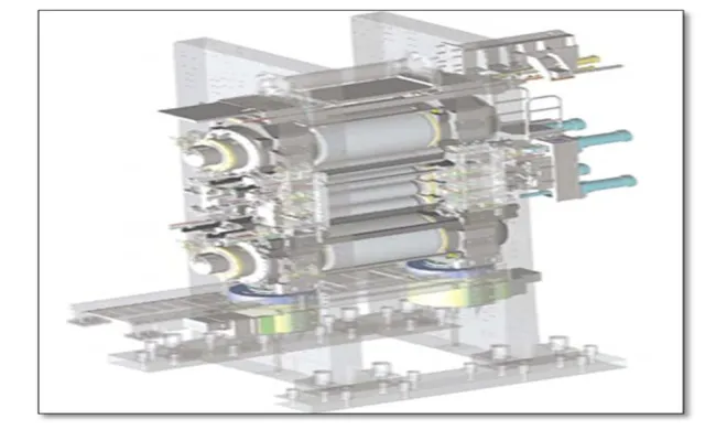
V TYPES OF ROLL CHOCKS
Roll Chocks are used in different applications and depending upon the nature of the application, the roll chocks are
broadly categorized into 4 types. These types of roll chocks are:
Work Roll Chocks
Back-up Roll Chocks
Upper Roll Chocks
Bottom Roll Chocks
VI FIELD OF THE PROJECT
This study relates to rolling mill bearing chock supports and more particularly to an improved wear plate structure
providing increased support and alignment stability for the work roll bearing chocks in a rolling mill.The project
may readily be adapted for use in various rolling mill configurations, but is particularly well-suited for application to
a four high strip mill and will be described in conjunction with such a mill. Mills of this type employ upper and
lower work rolls which cooperate to define a pass line at their nip for the strip to be rolled there between, with the
ends of the rolls being supported in bearing chocks which, in turn, are mounted in the windows of mill housings
disposed one on each side of the pass line, with the chocks and the work rolls supported therein being removable as
a unit from the operator side of the mill. Upper and lower backup rolls also have their ends supported in chocks
mounted in the mill housings, with power-driven screw downs forcing the backup rolls into rolling engagement with
the work rolls during operation of the mill.
The axes of the upper and lower work rolls and the large upper and lower backup rolls are contained in a common
vertical plane so that the extremely heavy workloads exerted by the power-driven screw downs, through the backup
roll chocks and rolls, to the work rolls should theoretically produce only a vertical load on the work bearing chocks
in the static load condition. However, minor misalignments inherent in such equipment as a result of manufacturing
tolerances, wear, strain, and the like, and as a result of loads produced by the roll drive and by the work piece
45 | P a g e
relation of the roll axes and, as a result, the mill stand housings must place heavy restraining loads on the work rollchocks. These heavy loads have, in the past, caused wear on the bearing surfaces of both work roll chocks and the
mill housing. To minimize this wear, and to facilitate maintenance of the roll stands, it has been conventional
practice to provide wear plates, or liners, in the form of high-strength hardened steel plates on the face of the mill
housing and on the adjacent face of the roll chocks. While these liner plates have generally been effective in
reducing wear and keeping the chocks centered in the mill housing, there have been instances where the chocks have
been permitted to move sufficiently to produce a hammering effect causing excessive wear on the liner plates and in
extreme cases to cause wear or damage to the face of the mill housing beneath the liner. This has been particularly
true in the case of the lower work roll chock which generally has been provided with substantially smaller liner plate
area than the top work roll chock. Examples of known rolling mills wherein liner plate for the bottom work roll
chock is substantially smaller than that of the top work roll chock can be found in the above-mentioned U.S. Pat.
No. 3,733,875 and U.S. Pat.No. 3,864,954. Other known rolling mill configurations similarly employ liner plates of
unequal area on the lower and upper work roll bearing chocks.
It is a primary object of the present invention to provide an improved chock structure for the work rolls of a rolling
mill.Another object of the invention is to provide a lower work roll bearing chock having an increased liner support
surface.Another object of the invention is to provide a rolling mill including upper and lower work roll bearing
chocks having liner plates rigidly mounted thereon and including means for providing an increased vertical
dimension for the lower work roll bearing chock liner plate to thereby provide greater strength and dimensional
stability for the lower work roll bearing chock. Another object is to provide a rolling mill in which the upper and
lower work roll chocks have substantially equal bearing face areas in contact with the supporting mill housing.
Configurations, the 4-high variety are the most widely used – both in single-stand and multi-stand tandem mills. The
2-high mill, which consists of two working rolls only and no other supporting rolls are mainly used for “skin-pass”
or temper rolling, the purpose of which is mainly to impart the desired mechanical properties rather than to cause
significant reductions in thickness.
46 | P a g e
VII EXPERIMENTAL SETUP
Software Analysis highlighted the Bottom Back Up Roll Chock with material OHNS is the one where the deflection
is maximum up to 1.1% and Mass reduction allowed up to 24.57%, Hence Bottom Back Up Roll Chock is selected
for the experimental analysis. A prototype model of scale 8:1 is manufactured with material OHNS and used for the
Experimental set up.
Experimental Set Up for Testing Scaled Model of Rolling Mill Chock
The main problem faced in using a standard material-testing machine for testing a rolling mill chock is the stress
developed. These rolling mill chocks are designed for a stress in the order of few microns.
The requirements of testing machine are summarized as follows:-
1) The machine should have sufficient stroke length to accommodate deflections.
2) The machine must be capable of exerting heavy loads in the range of tones.
3) The machine must be equipped with suitable fixture arrangement, which will simulate the actual mounting of the
rolling mill chocks in rolling mills.
4) The fixture should facilitate easy mounting of different types of rolling mill chocks with little modifications.
VIII ALL ROLLING MILL CHOCK ANALYSIS DATA GLANCE
Similarly for other chocks analysis is done and the analysis of all chocks is tabulated for the further conclusions.
Below graph indicates the stress distribution in the chock. Three materials and three trials have taken for the analysis
of chocks. Following graph shows the maximum stress induced in the chock at a glance which helps to compare
with each other.
47 | P a g e
Graph -Displacement Vs Material & Modification (Displacement in mm)Stress induced in the chock after modification II is 85.83 N/mm2, more than that of induced in existing chock after
modification I. This is happened because the material in which the induced stress is less have removed. Although the
stress in chock increased from existing to the modification II, but this induced stress is less than the yield tensile
strength of the consecutive materials. Also the deformation is increased from existing chock to chock after
modification II. But deformation is less than 1 mm which is general consideration. Hence the chock is safe.
In the Modification I as the stresses remain same while deflection reduces by 9.2%, hence it is recommended.
VIII OPTIMIZATION OF BOTTOM BACK UP ROLL CHOCK
0 2000 4000 6000 8000 10000
MASS IN Kg
Chart Title
EXISTING MODEL MODIFICATION I
48 | P a g e
The original weight of the top back up roll chock is 8240 kg. The sole objective of the analysis is to reduce theweight of the chock and hence to optimized chock. Then by modifying chock it got the weight equal to 7427 kg.
That is reduced weight equal to 813 kg. After that it took modification II to reduce further weight and hence to
optimized chock. In modification II, reduced the weight equal to 2025 kg. Removal of material could be done with
the help of the analysis result, from where the induced stress in chock is minimum. So Modification-I is
recommended as it will consider the mass reduction as the 9.8%.
IX CONCLUSION
Finite Element Analysis is a science which is used to calculate displacements (Deflections), stresses in components
under the loads acting on it. The results of Finite Element Analysis are used in conceptual studies of new designs,
product development and optimization of products.
For analysis and optimization, roll chock of cold rolling mill have chosen. Computer aided simulation of a Roll
chock is a novel concept to save the material without hampering the strength of the chock, by analysis of the actual
chock model on ANSYS (FEA software). Structural analysis is done with existing chock material Fe410 and
proposed material Fe316 and OHNS, with different dimensions as first and second modifications, Material OHNS
with first dimensional modification found suitable for the optimization of rolling chocks.
UTM is used for the simulation of forces to load the chock. The optimized chock would result into usage of less
material up to 24.57%, and would have enough strength compared to existing chocks, with increase of deflection up
to 1.1%. So it can be conclude that the design of roll chocks is optimized. It is reveal that there is a scope for
optimization of chock
REFERENCES
1. Remn-MinGuo,M.V.Loen “Design and Simulation of an entry edge guideControl SystemforTandemCold
Mills”JournalofManufacturing ScienceandEngineering February1999,Vol.121/69.
2. Yanping Sun Dechen Zhang “Research on the Vibration of Rolling Mill ”Advanced EM engineering Forum
Vol.23(2012) pp843-847.
3. PériclesGuedesAlves,JoséAdilson de Castro,LucianoPessanha Moreira,Elder Moreira Hemerly “Modeling,
Simulation and Identificationfor Control ofTandem Cold Metal Rolling”MaterialsResearch. 2012; 15(6): 928-936.
4. Antonsson E.K., Otto K.N., 1995, 'Imprecision in engineering design', ASME J. Mech. Des. B 117, 1995, 25-32.
5. K. Devarajan, K. PrakashMarimuthu and Dr. Ajith Ramesh “FEM Analysis of Effect of Rolling Parameters on
Cold Rolling Process” Bonfring International Journal of Industrial Engineering and Management Science, Vol. 2,
No. 1, March 2012.
6. Imre Kiss, Vasile George Cioata and VasileAlexa, “Increasing the rolling mill rolls quality in some
49 | P a g e
7. Sun Jianliang ,Peng Yan and Liu Hongmin, “Coupled Dynamic Modelling of Rolls Model and Metal Model forFour High Mill Based on Strip Crown Control”, Chinese Journal of Mechanical Engineering, 2011, 4, pp1- 7.
8. Baoyu Xu1, 2,Xudong Wang1, Yilun Liu 2, and Haichao Feng1 “Strip/Foil Rolling Mill Stochastic Excitation
Model and Its Stability”Journal of computers, vol.7,no 6,June2012.
9. Tanehiro Kikkawa, JP Steel Plantech Co.,3-1, Kinko-cho, Kanagawa-ku,Yokohama,“New Rolling Method of
Reversing Cold Rolling Mill”, AISTech Proceedings, 2012, pp.1771-1780.
10. U.S.Dixit P.S.Robi, D.K.Sarma–“Asystematic procedure for the design of a cold rolling mill” Journal of