Themed Section : Engineering and Technology © 2018 IJSRSET | Volume 5 | Issue 3 | Print ISSN: 2395-1990 | Online ISSN: 2394-4099
Design of Shared Aperture Microstrip Patch Antenna Array For
Conformal 5G Communications
G. S. Sudharsana Prasad*, K.Arun, M.Gulam Nabi Alsath
Electronics and Communication Engineering, Sri Sivasubramanya Nadar College of Engineering,Kalavakkam, Tamil Nadu, India
ABSTRACT
This paper presents a conformal shared aperture microstrip 2 x 2 array antenna designed for dual-band operation at 38 and 60 GHz frequencies on a flexible substrate (Rogers RO4003c). The window shaped slot is designed to operate at 38 GHz and the patches placed inside the window shaped slot are designed to operate at 60 GHz. Corporate feeding is employed to excite the patches operating at 60 GHz. The proposed antenna can bend to fit any shape of wearable device since it is designed on a flexible substrate. Application of this SAA is in wearable devices operating in 5G communication system. The antenna design has been simulated using CST microwave studio and finally the simulation results are presented.
Keywords: Shared aperture, 5G communication, Conformal antenna.
I. INTRODUCTION
Presently, Wireless Communication is the fastest growing field of the Communication field. There are many government and commercial applications where weight, size, cost, performance, ease of installation, aerodynamic profiles are the major constraints. In the last few years, the development of 5G technology represented one of the principle interests in the information and Communication field. Also, in today‟s environment, technology demands antennas which can operate on different wireless bands and should have different features like low cost, minimal weight, low profile and are capable of maintaining high performance over the operating frequency ranges.
The technological developments in the communication and biomedical fields have increased the demand for wearable devices such as smart
watches, smart bands, On-body health monitoring devices etc. This has led to the idea of flexible electronics where the devices are designed in order to comfortably fit on various body parts. In order to satisfy the demand for wearable devices, conformal antennas are also required. The developed conformal antenna design can be employed for wearable devices that work in 5G communication band.
signal strength to a better level compared to that obtained using one single frequency band.
The paper is aimed at developing a conformal shared aperture microstrip 2 x 2 array antenna designed for dual-band operation at 38 and 60GHz frequencies on a flexible substrate (Rogers RO4003c). Two different radiators, viz. window shaped slot and square patch antenna share a common aperture. Thus, the proposed antenna operates at both 38 GHz and 60GHz frequencies which will aid in the increased signal strength required for 5G communication systems.
The organization of the paper is as follows. Section II of this paper describes the steps involved in design of the antenna and Section III illustrates the simulated antenna performance. Finally in Section IV, the conclusion is presented.
II. DESIGN
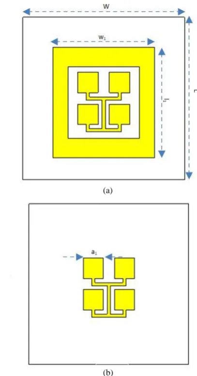
The basic design [3][4][5][6] is shown in Fig 1. The V-band patches are placed inside the Ka-band slot.
This can be done since the ratio between 60 GHz and 38 GHz is such that the Ka-band slot can accommodate
V-band patches inside it (frequency ratio between 60 and 38 GHz is about 1.57). In this case the Ka-band
slot is large enough to house a 2 x 2 V-band array. The V-band patches are connected using corporate feeding technique which is then excited in the middle using coaxial probe. The Ka-band patch is excited
using a coaxial probe again. The dimensions of the single array element is fixed to be 10 x 10 mm2 in
which 6.4 x 6.185 mm2 is the area of the Ka-band slot
and 1.26 x 1.26 mm2 is the area of each V-band
element inside the Ka-band slot. The radiators are
designed on a 0.203-mm-thick lossy RO4003c substrate with dielectric constant 3.55 and dissipation factor 0.0027.
Figure 1. Proposed SAA element. (a) Array element consisting of Ka-band slot and 2 x 2 array of V-band
patch. (b) 2 x 2 array of V-band patch corporate fed.
L=10 mm, W = 10 mm, l1 = 6.4 mm, w1 = 6.185 mm, a1
= 1.26 mm.
The antenna shown in Fig. 1 is then replicated to form a 4 x 4 array as shown in Fig. 2. This array is then bent in the form of a cylinder, to compare the characteristics of the antenna with the array element. Since the antenna is designed on a flexible substrate, the antenna‟s performance changes only by a small amount. The total area of the 2 x 2 antenna array is 20 x 20 mm2.
(a)
Figure 2. Proposed Shared Aperture Antenna (SAA) array. (a) 2 x 2 Shared Aperture array before performing bend operation. (b) Array antenna after
performing bend operation.
III.SIMULATION RESULTS
The proposed antenna was designed using CST microwave studio and the results obtained are discussed below. The slot radiating at 38 GHz was designed and simulated, the S-parameter characteristics for which is shown in Fig. 3
Figure 3. Simulated S-parameter characteristics of the Ka-band slot.
Similarly for the element radiating at 60 GHz, initially it was fed directly using coaxial probe and simulated to view its S-parameter plot. Then corporate feeding technique was employed in order to optimize the design and then simulated to observe its S-parameter characteristics. The S-parameter plot for the patch is shown in Fig. 4.
Figure 4. S-parameter characteristics of the 2 x 2V-band patch array
A. S-parameter characteristics of the proposed Shared Aperture Antenna array element
The optimum result was achieved after many design trials. The S-parameter characteristics of the array element are shown in Fig. 5. The Far-field radiation pattern shown in Fig. 6 and 7 show the radiation pattern of the antenna at 38 GHz and 60 GHz respectively.
Figure 5. S-parameter characteristics of the radiating element of Shared aperture antenna array
B. Farfield Radiation Pattern Of A Single Array Element
Figure 6. Farfield radiation pattern at 38 GHz
Figure 7. Farfield radiation pattern at 60 GHz
C. S-Parameter Characteristics Of Proposed Conformal Shared Aperture Antenna Array
At 38GHz, the return loss is below the acceptable value of -10dB from 38GHz to 39.1GHz and at 60GHz it is between 60 GHz to 62 GHz approximately.
Figure 8. S-Parameter measured for Shared Aperture Array Antenna
D.Farfield Radiation Pattern Of The Array Antenna
The Farfield realized gain is around 7 dB at 38GHz and around 10 dB at 60GHz.
Figure 9. Farfield radiation pattern at 38 GHz
Figure 10. Farfield radiation pattern at 60 GHz
IV.CONCLUSION
Thus a Shared-Aperture Microstrip Patch Antenna Array for Conformal 5G Communications for wearable devices is developed on a flexible substrate (Rogers O4003c). The rapid advancements in wearable devices in terms of technology, functionality, size and more real-time applications have increased the demand for flexible antennas. The proposed design can be a potential aid in designing a conformal antenna for wearable devices. In future, we are planning to implement proximity feeding technique in order to reduce the spurious radiation further and Specific Absorption Rate (SAR) calculations for various human body parts when exposed to the designed antenna.
V.REFERENCES
[1] Xu, H., Rappaport, T. S., Boyle, R. J., &Schaffner, J. H. (2000) „Measurements and models for 38-GHz point-to-multipoint radiowave propagation‟, IEEE Journal on Selected Areas in Communications, Vol.18, No.3, pp.310-321. [2] Rappaport, T. S., Ben-Dor, E., Murdock, J. N. and
[3] Constantine A. Balanis, “Microstrip Antennas,” in Antenna theory analysis and design, IIIrded. New Jersey, USA.
[4] Granholm, Johan, and Niels Skou. (2000) „Dual-frequency, dual-polarization microstrip antenna development for high-resolution, airborne SAR‟, Microwave Conference, Asia-Pacific.
[5] Shafai, L. L., Chamma, W. A., Barakat, M., Strickland, P. C. and Seguin, G. (2000) „Dual-band dual-polarized perforated microstrip antennas for SAR applications‟, Transactions on Antennas and Propagation, Vol.48, No.1, pp. 58-66. IEEE.
[6] Wang, Z., Xiao, L., Fang, L. and Meng, H. (2014,