www.ijaera.org 2015, IJAERA - All Rights Reserved 315
Buckling Analysis of Inflatable Cylinder by
using Experimental Setup
Bhaveshkumar N. Pasi1*, Vinayak H. Khatawate2
1PG Student, Mechanical Engineering Deptt, Pillai HOC College of Engg. & Tech., Navi Mumbai, India
*Corresponding Author E-mail: [email protected]
2Assistant Professor, Department of Mechanical Engineering, PIIT New-Panvel, Navi Mumbai, India
E-mail: [email protected]
Abstract: Inflatable structures belong to the family of tensile structures. Tensile structures are membrane like structures which require pre-stressing in order to sustain externally applied compressive loads. The pre-stressing is achieved by means of a pressure differential over the skin. In this paper, an inflatable cylinder is considered for analytical and experimental analysis and the cylinder is studied for its behavior for different cases of load application. In past, MATLAB codes were developed considering the beam to be constrained as hinged at one e nd and simply supported at the other. Parameters like buckling, deflection, wrinkling and stress-strain relationships of the cylinder were studied. In this paper buckling analysis of inflatable cylinder is carried out. The result obtained by experimental method is compared with the analytical results.
Keywords:Inflatable cylinder; Buckling; MATLAB; Stress; Experimental method
I. INTRODUCTION
In this paper, the buckling analysis of the beam is carried out using experimental setup. The results obtained by experimentation matched with the analytical results closely. It is a well-known fact that, due to unrealistic boundary conditions and unavoidable errors, the exact match between simulation results, analytical solution and experimental results could not be achieved. Therefore, an experimental model is set up and the detailed analysis of the same is performed. The comparison of experimental and analytical results will give a detailed insight into the behavior of inflatable beams. In this research work experimentation is carried out to demonstrate the buckling of an inflatable cylinder which can also be used to demonstrate the twisting, torsion, elongation, compression and bending of the cylinder. Finally, the results are validated and comparison is made with the analytical results.
II. WORKING OF EXPERIMENTAL SETUP
www.ijaera.org 2015, IJAERA - All Rights Reserved 316
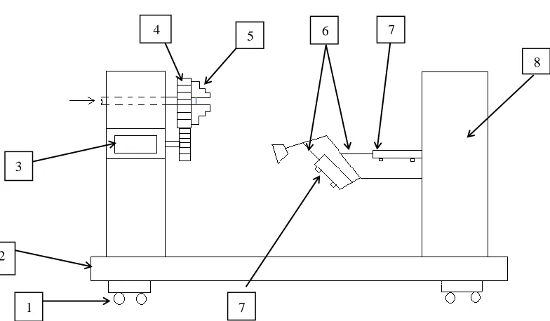
1. Wheel, 2. Base, 3. Steeper Motor, 4. Gear, 5. Chuck, 6. Piston Rod, 7. Pneumatic Cylinder, 8. Column
Figure 1: Schematic Diagram of Experimental Setup
III. OBSERVATION TABLE
Table I: Readings for Buckling Load Validation
Sr.
No.
Master Cylinder Supporting Cylinder Rotameter Reading
(LPM) Inlet
(kgf/cm2)
Outlet (kgf/cm2)
Inlet (kgf/cm2)
Outlet (kgf/cm2)
01. 8 3 6.2 0 30
02. 6 2 4 0 30
03. 8 3 5.2 0 30
04. 8 3 4.7 0 30
05. 8 3 3 0 30
06. 8 3 7 0 30
07. 8 3 6.7 0 30
A. Theoretical Analysis
Discharge = Q = 30 LPM = 30 x 10-3 m3/min
m3/sec
Q = 0.5 * 10-3 m3/sec
3
1 2
4 5 7
7
6
www.ijaera.org 2015, IJAERA - All Rights Reserved 317 Density of air = 1 kg/m3
Mass flow rate = m = 1 * 0.5 * 10-3 kg/sec
Flow of air is allowed for 10 sec
Mass accumulated = m * t = (1 * 0.5 * 10-3)* 10 = 0.5 * 10-2 kg
Assume, diameter and length of inflatable cylinder as 4 cm and 52 cm respectively.
We know that,
………. Equation (1) Therefore, Volume is given by
V = (π/4) * (0.04)2 * 0.52
V = 6.53 * 10-4 m3
T = 25 0C (Ambient temperature)
Substitute the value of volume and temperature in equation (1), therefore
p = 654869.8 N/m2 p = 6.5487 kgf/cm2
Minimum tensile force
= 654869.8 * * (0.04)2
= 823.04 N ……… Theoretical Buckling Load
B. Experimental Analysis
Differential pressure = (8 – 3) kgf/cm2
= 5 kgf/cm2
= 50 N/cm2
By measurement, pneumatic cylinder effective diameter = 3 cm
Therefore, force on main cylinder is given by,
= 50 * π/4 * (3)2
= 353.42 N
Position of supporting cylinder = 40o (Average)
Differential pressure = (6.2 – 0) kgf/cm2
www.ijaera.org 2015, IJAERA - All Rights Reserved 318
Therefore, force on cylinder = 62 * π/4 * (3)2 = 438.25 N
As the horizontal component of force is responsible for buckling, hence consider horizontal component of force for analysis.
Component of force in horizontal direction = 438.25 cos 40o = 335.71 N
Total load = 438.25 + 335.71 = 773.96 N ……… (Practical load at which buckling takes place)
IV. COMPARISON OF RESULTS
Table II: Result Comparison
Sr.
No. Parameters Analytical (N) Experimental (N)
Percentage Variation
01. Buckling Load 823.04 773.96 5.96%
Experimental result obtained for buckling load is closely matching with analytical result. From this result it can be concluded that model with inflatable material properties can be solved with newly developed experimental setup. Small variation in result is obtained because of use of simplified boundary conditions in analytical solution.
0 100
200
300 400 500 600
700
800 900 1000
3 4 4.7 5.2 6.2 6.7 7
B
u
ckl
in
g Lo
ad
in
N
e
wt
o
n
s
Theoretical Load v/s Experimental Load
Expt. Load
Th. Load
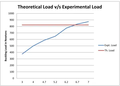
Figure 2: Comparison of Theoretical Buckling Load with Experimental Buckling Load
From figure 2 it is found that experimental buckling load is very close to theoretical buckling load at differential pressure of 6.2 kgf/cm2. If the value of differential pressure is taken below the 6.2
www.ijaera.org 2015, IJAERA - All Rights Reserved 319
observed. If the value of differential pressure is taken more than 6.2 kgf/cm2 then experimental
buckling load exceeds theoretical b uckling load. Hence, 6.2 kgf/cm2 pressure value is selected to
obtain the various design parameters of interest of inflatable cylinder.
V. CONCLUSIONS
From the literature survey it is concluded that enough experimental data is not available for inflatable structures. Therefore, validation in finite element analysis is not possible. Hence, study started with need of development of experimental setup for cylindrical inflatable structures. After developing an experimental setup for cylindrical inflatable structures, experimentation is carried out to determine the buckling load capacity. Finally, results obtained from experimentation for buckling load closely matches with analytical result with error less than 6%. This suggests that buckling load of magnitude 823 N initiates buckling.
VI. REFERENCES
[1] Jeffrey D. Suhey (2005), “Numerical Modeling and Design of Inflatable Structures- application to open-ocean- aquaculture cages”, Elsevier, Aqua cultural engineering, Vol-33, pp. 285-303.
[2] P. Halswell (2013), “The Effect of Flexibility on the Design and Performance of Inflatable Boats”,
International Journal of Engineering and Technology, ISSN 0974-3154 Vol-6, pp. 197-202.
[3] Richa Verma (2013), “Advancement in Inflatable –A review”, International Journal of Engineering and
Technology. ISSN 0974-3154 Vol-6, pp. 477-482.
[4] Arjun C.C., Sreekanth N.V., K. Guruprasad (2013), “Analytical and numerical studies of inflatable
structures for aeronautical applications”, International Conference on Advanced Research in Mechanical Engineering, Chennai, ISBN: 978-93-82208-97-6
[5] E. Jacquelin (2005), “Hydrodynamics of high-speed marine vehicles”, Cambridge University Press,