IJSRSET1841054 | Received : 25 Sep 2018 | Accepted : 05 Oct 2018 | September-October-2018 [ 4 (10) : 248-261]
Optimization of Abrasive Water Jet Machining Process
Parameters for Inconel-825 By Using Grey Taguchi Method
G. K. Kiran Kumar*1,C. Bhavani Sankar2
*1Department of Mechanical Engineering, Siddartha Institue of Science and Technology, Puttur, India
2Department of Mechanical Engineering, Siddharth Institue of Engineering and Technology, Puttur, India
ABSTRACT
Abrasive Water Jet Machining (AWJM) is a versatile and fastest growing machining process primarily used to machine hard and difficult to machine materials. This machine is also used to machine soft, thick, light, thin and fragile materials. It compliments other technologies such as Milling, Laser, EDM etc…. It doesn‟t possess any mechanical stress to operator and environmental hazards. AWJM cut the material accurately unlike any other machining process. AWJM mainly adopted by aerospace industry for cutting high strength materials and other composites. It finds most of its applications in machining of gas turbines, rocket motors, space craft, nuclear power and pumps etc., very thin stream of about 0.004 to 0.010 dia. can be cut and material loss is also less due to cutting. Standoff distance between mixing tube and work part is typically 2 to 4mm important to keep to a minimum to get superior surface finish. The objective of this research is to analysis the effect of input process parameters and to optimize process parameters for achieving optimizing Processes responses such as Metal Removal Rate(MRR), Surface roughness (Ra), and Kerf width simultaneously while machining on the nickel-chromium based super alloy INCONEL 825 using AWJM process. It is a precipitation hardened material and has good creep-rupture strength. It shows good mechanical properties even at high temperatures. Applications are Intricate shapes can be easily obtained for Aerospace products.
Keywords : AWJM, Material Removal Rate, Surface Roughness, Kerf Width Nomenclature:
AWJM : Abrasive water jet machine MRR : material removal rate
DOF : degree of freedom DOE : Design of experiments
I. INTRODUCTION
Water jets were introduced in the United States during the 1970‟s, and were utilized merely for cleaning purposes. As the technology developed to include abrasive water jets, new applications were discovered. However, until recently this tool had not been used to a great extent in the construction industry. The water jet has shown that it can do things that other technologies simply cannot. From
cutting thin details in stone, glass and metals; to rapid hole drilling of titanium; to cutting of food, to the killing of pathogens in beverages and dips, the water jet has proven itself unique.
water jet is allowed to strike a given work piece. During this process its kinetic energy is converted to pressure energy. This induces a stress on the work piece. When this induced stress is high enough, unwanted particles of the work piece are automatically removed.
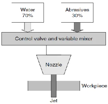
Fig.1. Setup of Abrasive water jet machining process
The apparatus of water jet machining consists of the following components:
Reservoir: It is used for storing water that is to be used in the machining operation.
Pump: It pumps the water from the reservoir. High pressure intensifier pumps are used to pressurize the water as high as 55,000 psi. For the abrasive water jet, the operating pressure ranges from 31,000 to 37,000 psi. At this high pressure the flow rate of the water is reduced greatly.
Intensifier: It is connected to the pump. It pressurizes the water acquired from the pump to a desired level.
Accumulator: It is used for temporarily storing the pressurized water. It is connected to the flow regulator through a control valve.
Fig. 2. Abrasive and water mixing
Control Valve: It controls the direction and pressure of pressurized water that is to be supplied to the nozzle.
Flow regulator: It is used to regulate the flow of water.
II. DIFFERENT PHASES OF EXPERIMENTATION
To achieve the objectives, present research has been done in four phases
Phase-I
Development of Design of experiment (DOE) as per ranges of processes variables in AWJM machine. Experimentation of AWJM is done on Inconel-825 material as per DOE.Measuring the processes responses on-line and offline.
Phase-II
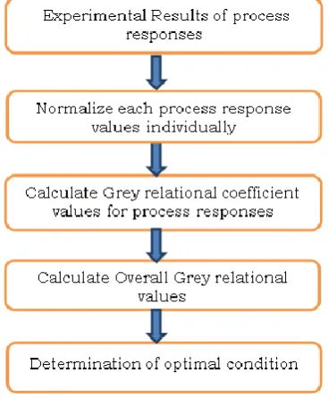
Development of Multi-objective optimization model by using Grey-taguchi technique.
Determination of optimal setting of AWJM Processes parameters for processes responses simultaneously. Phase-III
Development of mathematical model for MRR, Surface roughness.
Development of Grey Relational Analysis Traverse speed, Abrasive flow rate, Standoff distance by using Grey taguchi analysis.
Phase-IV
Determination of optimal setting of AWJM processes parameters for processes responses simultaneously.
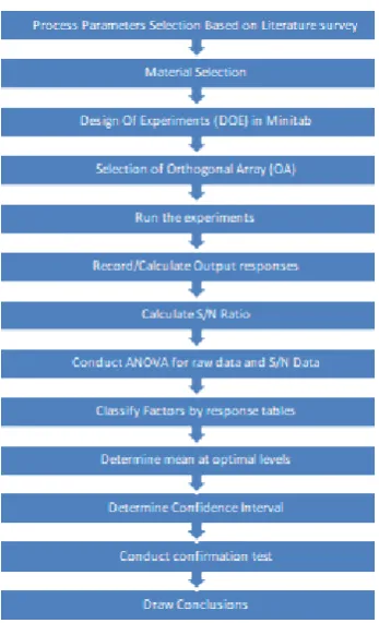
Methodology (or) Step by step procedure followed in present work :
Fig.3. Flow chart followed in present work
OPTIMIZING TECHNIQUES:
Taguchi Technique:
Dr. Gene chi Taguchi is a Japanese researcher who spent quite a bit of his expert life examining approaches to enhance the nature of fabricated items. After World War II, the Japanese phone framework was gravely harmed and useless. Taguchi was designated as leader of Japan's recently framed Electrical Communications Laboratories (ECL) of Nippon Telephone and Telegraph Company. Quite a bit of his exploration at ECL included building up a thorough quality change philosophy that included utilization of the DOE strategy.
Response Surface Methodology:
Response Surface Methodology (RSM) is a collection of mathematical and statistical techniques that are
useful for modeling and analysis of problems in which the response is influenced by several variables and the main aim is to find the correlation between the response and the variables i.e., it can be used for optimizing the response. In the present study water pressure, abrasive flow rate, orifice diameter, focusing nozzle diameter and standoff distance are chosen as the process parameters and varied at three levels and the commonly used constant parameters of AWJM. In Response surface design, a Box-Behnken design table with 24 experiments was selected.
Genetic Algorithm:
Genetic algorithms have been used in science and engineering as adaptive algorithms for solving practical problems and as computational models of natural evolutionary systems. Genetic Algorithms (GAs) are adaptive heuristic search algorithm based on the evolutionary ideas of natural selection and genetics. As such they represent an intelligent exploitation of a random search used to solve optimization problems. Although randomized, GAs are by no means random, instead they exploit historical information to direct the search into the region of better performance within the search space.
Fuzzy Logics:
Mat Lab:
MATLAB, short for MATrix LABoratory is a programming bundle particularly intended for brisk and simple experimental counts and I/O. It has actually several inherent capacities for a wide assortment of calculations and numerous tool stashes intended for particular examination disciplines, including insights, improvement, arrangement of fractional differential comparisons, information investigation.
III. EXPERIMENTAL DESIGN METHODOLOGY
DESIGN OF EXPERIMENT (DOE) TECHNIQUES:
The Design of an experiment is the synchronous calculation of two or more variables for their capacity to influence the resultant normal. To satisfy this in a successful and accurately appropriate form, the levels of the components are removed in an energetic method, the results specific test combinations are observed, and the complete set of results is poor depressed to focus the powerful elements and preferred levels, and whether expands or diminishes.
The DOE methodology is separated into three fundamental stages :
Arranging Phase:
The arranging stage is most dynamic stage for the test to give the normal data. An experimenter will learn currently and over the data is in a positive sense and negative sense. Positive data is an ID of which variables and which levels lead to improve piece implementation. Negative data is a sign of which components don't quick change.
Conducting phase:
Conducting stage is the most supreme stage, when the test results are actually collected. On the off chance that experimenters are decently arranged and led, the dissection is really much less demanding and
more horizontal to yield positive data about elements and levels.
Analysis phase:
Analysis phase is the point at which the positive data regarding the selected components and levels is produced dedicated around the past two stages. The dissection stage is minimum precarious regarding whether the trial will effectively produce positive results. These decisions are made with the help of various analytical techniques mostly used the analysis of variance (ANOVA). The advanced proposition is the collection of numerical results and numerical techniques for determining and identifying the best result from a collecting of options without demanding to clearly explain and measure all possible selections.
There are different techniques for design of experiment techniques are there for design and conducting experiments. These are
[1] Factorial design
[2] Response surface methodology [3] Mixture design
[4] Taguchi design
TAGUCHI TECHNIQUE :
production just to the manufacturing time. The customer complaints and dissatisfaction, the fail product money and time spent by customer. And loss of the market share.
Fig.4. Screenshots of DOE in Minitab software
Types of Designs in Taguchi Technique: Taguchi design follows the four steps:
[1].Robust design [2].Concept design
[3].Structure design (Parameter design) and [4].Acceptance design (Tolerance design)
Robust design:
The design expresses that product and directions must to be planned so they are in alienable escape free and of high quality. Design performance is insensitive to variation in science and engineering.
Concept design:
Model designing is the development of investigative competition technology towards creates products. The procedure knowledge choice and method proposal choice. In this area could be decrease fabrication cost and outcomes in high feature products.
Parameter design:
The design indicates to the determination of control elements and the variables determination of ultimate levels for each of the components, control variables will be in methodology parameters such an item is practically. The high level performance below ranges of conditions exits. Control calculates that are to be located at ultimate levels to increase the quality and decrease the affect capability to noise in Dimensions of parts. Noise Factors express to the demand that is standard in creation. Dimensional variation and operating Temperature. The design parameter one a time a first feasible design is finding to be an approach to design optimization. However, leads to expense of time for completing the design. Optimize the design so that it improves quality and reduces cost.
Phases in Taguchi Technique:
[1].Selection of control factors as per noise factors of main function with number of levels.
[2].Selection of the number of tests to be carried out or sort of Orthogonal Array (OA) in the form of matrix.
[3].Selection of noise factor to be optimizes.
[4].Running the tests as per predesigned orthogonal array matrix in order.
[5].Foretell the optimum levels of control factors with their corresponding Response factors.
[6].Rerun the tests corresponding to optimum levels to conform them as optimum levels of control factors.
Selection of Orthogonal Array (OA):
refers to corresponding output parameters for the process. The Degree of Freedom (DOF) value for the Overall Mean is 1. DOF for a Control Factor = No. of Levels – 1
For example, there is Control Factors X and Y, with three levels and the DOF for „X‟, and „Y‟ is?
Solution: DOF for „X‟ or „Y‟= No. of Levels – 1, DOF for „X‟ or „Y‟= 3-1 = 2.
But, DOF for interaction of „X‟ and „Y‟ is,
DOF for „XY‟ = (No. of Levels in „X‟ - 1) × (No. of Levels in „Y‟ -1)
= (3-1) × (3-1)
DOF for interaction of „X‟ and „Y‟ (DOF for „XY‟) = 4.
As per Taguchi technique, the processes parameters of 5 level design has two degree of freedom (DOF) this gives a total of 5-1=4. 3 parameters are considered DOF for three processes variables for this research. The condition for selecting OA is the DOFs for selected OA must be higher than DOFs required for experiment is 12 so, the nearest OA available for satisfying the condition of selecting OA is L25 have 12 DOF‟s. The selected L25 OA in terms of coded factors has been given in table 5.2.
DOF for a Control Factor = No. of Levels – 1 DOF for A = 5-1 = 4
Total DOF = 12
OA Selection Criterion:
L 25 OA was selected for carrying out experiments
Levels of Process Parameters
WORK PIECE MATERIAL:
INCOLONEL alloy 825 is a nickel-iron-chromium alloy with additions of molybdenum, copper, and titanium. The alloy‟s chemical composition, given in Table is designed to provide exceptional resistance to many corrosive environments. The nickel content is sufficient for resistance to chloride-ion stress-corrosion cracking. The nickel, in conjunction with the molybdenum and copper, also gives outstanding resistance to reducing environments such as those containing sulfuric and phosphoric acids. The molybdenum also aids resistance to pitting and crevice corrosion. The alloy‟s chromium content confers resistance to a variety of oxidizing substances such as nitric acid, nitrates and oxidizing salt. The titanium addition serves, with an appropriate heat treatment, to stabilize the alloy against sensitization to intergranular corrosion.
Application:
1.Chemical processing, acid production
2.Pollution control, oil and gas recovery and .Pickling operations
3.Nuclear fuel reprocessing, and handling of radioactive wastes
Magnification:
The micro structure of INCONEL-825 seen with magnifying lens as below
MACHINE DETAILS :
Description Abrasive Water Jet Machining Controlling of
Machine
CNC
Voltage 415 V
Frequency 50 Hz
Phases 3
Power 547 W
Current 1.8 A
Table size 3 * 3 * 1.5
Travel X-axis – 3000mm, Y-axis – 3000mm, Z-axis – 260mm Nozzle diameter 1.1 mm
Abrasive type Garnet
Abrasive size 80 Mesh
Orifice diameter 0.35 mm
Focussing tube diameter
8 mm
Water pressure 3500 bars
Water flow rate 3.5 litre/min
Impact angle 90 degrees
Nozzle Length 80 mm
IV.MEASUREMENT OF EXPERIMENTAL PARAMETERS
Mechanism and Evaluation of Metal Removal Rate (MRR):
Metal Removal Rate (MRR) is the rate at which the material is removed from the work piece. The MRR is defined as the ratio of the amount of metal removed from the work piece in mm3 to time taken for
machining in min.
MRR=
( ) ( )
Where, W = Va - v
Va= volume of machined specimen on the work piece.
v = volume of cut piece from the specimen.
Here we get MRR in terms of mm3/min. To find out
the MRR in terms of gm/min, the value should be multiplied with the density of the material chosen.
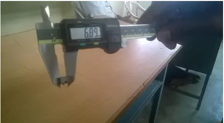
Mechanism and Evaluation of Kerf width:
Kerf width is defined as the width of the material that is removed by a cutting process.
Kerf width =
Where, S1 = side of the machined specimen on the
work piece.
S2 = side of the cut piece from the specimen.
Mechanism and Evaluation of Surface roughness (Ra): In this work the surface roughness is measured by Mitutoyo surftest SJ-201P
Fig 6. Mitutoyo surftest SJ-201P instrument
Before machining:
The actual weight of the super alloy after purchasing was found out to be 984.94gm.
After machining:
The weight of the super alloy (without 25 specimens) and the weight of the 25 specimens and the amount of metal removed during machining calculated from metal removal rate combinely turned out to be 991gm which is quiet near to the original weight of the super alloy INCONEL-825 i.e., 984.94gm. Hence it is proven that AWJM is a precise and accurate machine.
Fig.5. Measurement of width in vernier
calliper
V. RESULTS AND DISCUSSIONS
we require to optimize process parameters for multi responses, so Grey-Taguchi technique is employed for optimizing process parameters to get maximizing Metal Removal Rate, minimum Kerf Width and Surface Roughness simultaneously during Abrasive water jet machining (AWJM) process
TABLE.1. Taguchi‟s L25 Orthogonal Array with Experimental Results
S.NO
TRANSVERSE SPEED (mm/min)
ABRASIVE FLOW RATE (gm/min)
STAND OFF
DISTANCE (mm)
Kerf
Width MRR
Surface roughness(Ra)
1 40 50 1 1.17 1.921 0.0145
2 40 100 2 1.205 1.826 0.0135
3 40 150 3 1.235 1.368 0.013
4 40 200 4 1.3 1.85 0.0135
5 40 250 5 1.28 4.69 0.0135
6 50 50 2 1.15 2.9 0.015
7 50 100 3 1.11 3.7 0.0145
8 50 150 4 1.145 4.5 0.0155
9 50 200 5 1.205 4.9 0.0145
10 50 250 1 1.115 4.53 0.013
11 60 50 3 0.975 3.52 0.017
12 60 100 4 1.07 4.9 0.0155
13 60 150 5 1.135 6.19 0.014
14 60 200 1 1.105 4.76 0.0135
15 60 250 2 1.125 4.84 0.013
16 70 50 4 1.1 5.71 0.0135
17 70 100 5 1.125 6.63 0.017
18 70 150 1 1.065 7.02 0.015
19 70 200 2 1.175 6.75 0.016
20 70 250 3 1.175 6.574 0.0135
21 80 50 5 1.06 5.53 0.0145
22 80 100 1 1.045 5.69 0.015
23 80 150 2 1.115 7.57 0.0135
24 80 200 3 1.135 7.037 0.013
25 80 250 4 1.16 8.087 0.015
TABLE.2. Experimental results of Kerf Width, MRR and Surface Roughness and their S/N ratio‟s
TRANSVERSE SPEED (mm/min)
ABRASIVE FLOW RATE (gm/min)
STAND OFF DISTANCE (mm)
Kerf
Width S/N Ratio
Surface roughness (Ra)
S/N Ratio
MRR S/N Ratio
40 50 1 1.17 1.17691 0.0145 37.1206 1.921 4.5292
TABLE.3. ANOVA FOR GREY RELATIONAL GRADE
Source DF Seq. SS Seq. MS F-Value %
Contribution
A 4 0.08289 0.020723 5.21 48.39
B 4 0.02907 0.007268 1.83 16.97
C 4 0.01161 0.002902 0.73 6.778
Error 12 0.04771 0.003976 27.85
Total 24 0.17128
40 150 3 1.235 1.74189 0.013 37.5629 1.368 5.37703
40 200 4 1.3 2.30265 0.0135 37.3603 1.85 6.83383
40 250 5 1.28 2.25655 0.0135 37.6132 4.69 10.3073
50 50 2 1.15 0.920738 0.015 36.5855 2.9 9.76564
50 100 3 1.11 0.849753 0.0145 36.4888 3.7 10.1800
50 150 4 1.145 1.29409 0.0155 36.7462 4.5 12.4554
50 200 5 1.205 1.67370 0.0145 36.7642 4.9 14.2456
50 250 1 1.115 1.12348 0.013 37.3533 4.53 13.9554
60 50 3 0.975 0.183494 0.017 36.5723 3.52 10.4044
60 100 4 1.07 0.576817 0.0155 36.1869 4.9 13.0590
60 150 5 1.135 0.840009 0.014 36.6650 6.19 15.6677
60 200 1 1.105 0.715494 0.0135 37.0192 4.76 13.6942
60 250 2 1.125 1.04217 0.013 37.3330 4.84 14.9924
70 50 4 1.1 0.779600 0.0135 36.0622 5.71 14.5631
70 100 5 1.125 0.991775 0.017 35.8974 6.63 17.5511
70 150 1 1.065 0.750846 0.015 36.7117 7.02 16.3962
70 200 2 1.175 1.50323 0.016 36.7906 6.75 16.0110
70 250 3 1.175 1.17397 0.0135 37.1116 6.574 16.9109
80 50 5 1.06 0.630993 0.0145 36.4673 5.53 16.5743
80 100 1 1.045 0.339047 0.015 36.6387 5.69 15.7986
80 150 2 1.115 0.975012 0.0135 37.1777 7.57 16.2320
80 200 3 1.135 1.07146 0.013 37.2638 7.037 15.4486
TABLE.4.RESPONSE TABLE FOR GREY RELATIONAL GRADE (S/N RATIO)
Level Transverse Speed (A)
Abrasive Flow Rate (B)
Stand Off Distance (C)
1 5.760 5.282 4.407
2 5.700 5.223 4.874
3 4.269 4.482 4.298
4 4.333 4.726 5.119
5 3.559 3.907 4.923
Delta 2.202 1.375 0.821
Rank 1 2 3
TABLE.5.RESPONSE TABLE FOR GREY RELATIONAL GRADE (MEANS)
Level
Transverse Speed (A)
Abrasive Flow Rate (B)
Stand Off Distance (C)
1 0.5167 0.5500 0.6080
2 0.5240 0.5493 0.5799
3 0.6144 0.6030 0.6148
4 0.6092 0.5896 0.5600
5 0.6672 0.6396 0.5688
Delta 0.1505 0.0903 0.0548
Rank 1 2 3
GRAPHS :
Main effect plot for Grey relational grade
PREDICTION OF RESPONSE VALUES FOR OPTIMUM LEVELS AS PER GREY-TAGUCHI TECHNIQUE: From means of each level of process parameters we will construct a response table as following :
TABLE.6. RESPONSE TABLE FOR MEANS OF GREY-RELATIONAL GRADE
Level Transverse Speed (A) Abrasive Flow Rate (B) Stand Off Distance (C)
1 0.5167 0.5500 0.6080
2 0.5240 0.5493 0.5799
3 0.6144 0.6030 0.6148
4 0.6092 0.5896 0.5600*
5 0.6672* 0.6396* 0.5688
Delta 0.1505 0.0903 0.0548
Rank 1 2 3
From the response table the optimal condition for maximizing Metal Removal Rate, minimum Kerf Width and Surface roughness simultaneously in Abrasive Water Jet Machining (AWJM) process, is found to be A5 B5 C3 i.e. Transverse speed is 80 mm/min, Abrasive Flow Rate is 250 gm/min and Stand Off Distance is 3 mm. For this optimal setting A5 B5 C4 conducted experimentation for validating results.
TABLE.7. OPTIMUM PARAMETER CONTROL LEVEL
Process response Optimal setting
Actual Value
Experimental
Value % of Error Metal Removal Rate
A5 B5 C3
8.087 7.89 2.4
Kerf width 1.16 1.16 0
Surface Roughness 0.015 0.0155 -3.33
VI.CONCLUSION
In this present analysis of various parameters and on the basis of experimental results, analysis of variance (ANOVA), and SN Ratio the following conclusions can be drawn for effective machining of INCONEL-825 by AWJM process as follows:
Traverse Speed (TS) is the most significant factor on MRR during AWJM. Meanwhile Abrasive Flow Rate and Standoff distance is sub significant in influencing.
In case of surface Roughness Abrasive Flow Rate is most significant control factor.
In case of Metal Remove Rate (MRR) & Surface Roughness Transverse speed & Abrasive Flow Rate are most significant control factors.
The optimal condition for maximizing Metal Removal Rate, minimum Kerf Width and Surface roughness simultaneously in Abrasive Water Jet Machining (AWJM) process, is found to be A5 B5 C3 i.e.
Transverse speed is 80 mm/min, Abrasive Flow Rate is 250 gm/min and Stand Off Distance is 3 mm
VII.
REFERENCES
[1]. D Patel, P. Tandon "CIRP Journal of Manufacturing Science and Technology", ISSN: 1755-5817, September 10 (2015).
[2]. N Tamannaee, J.K. Spelt, M. Papini," Abrasive slurry jet micro-machining of edges, planar areas and transitional slopes in a talc-filled co-polymer", Precision Engineering ,Department of Mechanical and Industrial Engineering, University of Toronto, Department of Mechanical and Industrial Engineering, Ryerson University, Toronto, Canada , Issue 24, June 2015.
[3]. Fritz Klocke, Sein Leung Soo , Bernhard Karpuschewski, John A. Webster, Donka
Novovic, Amr Elfizy, Dragos A. Axinte, Stefan Tnissen," Abrasive machining of advanced aerospace alloys and composites",CIRP Annals - Manufacturing Technology, Volume 64,Issue 2, May 2015.
[4]. Derzija Begic-Hajdarevic, Ahmet Cekic, Muhamed Mehmedovic, Almina Djelmic"Experimental Study on Surface Roughness in Abrasive Water JetCutting" 25th DAAAM International Symposium on Intelligent Manufacturing and Automation, ISSN: 1877-7058, 2015.
[5]. B Satyanarayana, G. Srikar," Optimization of abrasive water jet machining process parameters using Taguchi Grey RelationalAnalysis(TGRA)", Proceedings of 13th IRF International Conference, Pune , India, ISBN: 978-93-84209-37-7, Issue 20,July 2014.
[6]. Vijay Kumar Pal, S.K.Choudhury“ APPLICATION
OF ABRASIVE WATER JET MACHINING
INFABRICATING MICRO TOOLS FOR EDM FOR PRODUCING ARRAY OF SQUARE HOLES” All India Manufacturing Technology, Design and Research Conference (AIMTDR), December 12th– 14th, 2014.
[7]. Sreekesh K and Dr. Govindan P“A REVIEW ON
ABRASIVE WATER JET CUTTING” International Journal of Recent advances in Mechanical Engineering (IJMECH), Vol.3, No.3, August 2014.
[8]. S. R. Patel, Dr. A. A. Shaikh ,”Control and
measurement of abrasive flow rate in an Abrasive
Waterjet Machine”,International journal of
innovative Research in Science, Engineering and Technology, ISSN: 2319-8753 ,Volume 2,Issue 12,December 2013.
[9]. Cristian Birtu, Valeriu Avramescu,” Abrasive water jet cutting- Technique, Equipment,Performances”, Nonconventional Technologies Review,Romania, Issue March ,2012.
[10]. M. Chithirai Pon Selvan and N. Mohana Sundara Raju“ASSESSMENT OF PROCESS PARAMETERS
INABRASIVE WATERJET CUTTING
[11]. Veselko Mutavgjic,Zoran Jurkovic, Marina
Franulovic, Milenko Sekulic,“Experimental
investigation of surface roughness obtained by Abrasive Water jet machining”, 15th International Research/Expert Conference ,“Trends in the
Development of Machinery and Associated
Technology”, Prague, Czech Republic , Issue 12,September 2011.
[12]. S. R. Patel, Dr. A. A. Shaikh ,"Control and measurement of abrasive flow rate in an Abrasive Waterjet Machine",International journal of innovative Research in Science, Engineering and Technology, ISSN: 2319-8753 ,Volume 2,Issue 12,December 2013.
[13]. D. Patel, P. Tandon “CIRP Journal of Manufacturing Science and Technology”