Themed Section : Engineering and Technology
Development of adjustable systems for a Go-Kart
Abhijeet Singh*, Tarun Singh, Vansh Mudgil
Mechanical Department, Manav Rachna University, Faridabad, Haryana, India
ABSTRACT
A go kart is a small racing car with a lightweight and skeleton body. It is used in traditional kart racing and for amusement purposes. The main aim of the project is to develop a go kart which is drivable by majority of the people having different height and age. We equipped our kart not only with the mandatory systems but also with innovative systems such as adjustable engine mounting, adjustable camber settings and adjustable pedals.
All these systems are successfully designed and fabricated without compromising the weight of the kart which has improved the vehicle dynamics. Safety and ergonomics of the vehicle have been considered throughout from designing till the kart is fabricated. While participating in any racing event for a competition, kart must be tuned according to the driver and with the help of these innovations karts can be tuned very quickly also reducing the repairing and maintenance time.
Keywords: Engine mounting, Camber setting, Pedal system, Material analysis
I.
INTRODUCTION
E A Go-Kart is a small four-wheeled vehicle. Go-karts are available in all shapes and forms, from motor less models to high-powered racing machines, some like Super Karts, being able to beat racing cars on long circuits. It is used in racing as well as for recreational driving purposes. Go-karts do not have suspensions nor differential. Therefore, the dynamics of karts is significantly different from that of other four-wheeled vehicles. The absence of rear axle differential makes the rear wheels to have a strictly correlated longitudinal slip and this characteristic makes it more difficult for a kart to turn than cars [1].
Motorsport is an expensive sport which needs a lot of professionalism. But go-karts have made it possible for common people to experience the thrills of motorsport with minimum restrictions. For the very first time go-kart was developed in United States in 1950s, in which an engine of the lawn machine was used. Go-kart was a non-popular sport in the earlier stages of its development, but now a days, it has emerged as a popular motor sport. Not only
professionals, in the present scenario go-kart is very well in reach of people of various age groups. Till 1960s, go-karts used to have engines in the rear. But in later years of 60s, various changes pertinent to design were introduced.
form an organized pattern for go-kart motorsport. In 1961, GKCA published kart magazines named “The Karter” issued on February 1961. The CIKFIA technical regulations [3] published the general design concepts of competition go-kart in every respect, and clearly classified competition go-kart into several classes according to the displacements and some special regulations.
The idea was to develop a go kart, as shown in figure 1., so that the person of any age group and height could drive the vehicle, regardless of his/her driving skills. Adjustable brake and accelerator pedals were designed and installed for this very purpose. The provision of changing camber settings was provided along with the adjustable engine mounting, allowing engine to move forward or backward, thus easing the installation of the engine and the chain. The material of the go-kart was selected on the basis of calculations and using analysis software making the gross weight of the go-kart as low as possible.
Figure1. Actual picture of Go-kart
A. Main systems of Go-kart
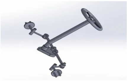
i)Steering System:
The function of steering is to ensure that the wheels are pointing in the desired directions. Steering system consists of steering wheel, which is mounted on the steering column, which is further connected to the tie
the wheels. Ackerman principle has been used in designing the vehicle as shown in figure 2. & figure 3.
Figure 1. Bottom view of steering system
Figure 3. Isometric view of steering system
Ackermann steering mechanism is a four bar linkage mechanism. It consists of turning pairs and no sliding pairs. This helps to decrease the wear and tear of steering mechanism. The Ackerman principle expresses how the steering geometry must be designed to make both front wheels follow proper arc while turning the kart. The concept of Ackerman is to have all four wheels roll without slipping, around a common point during a turn. This common point is known as instantaneous centre of curvature (ICC) [4-5].
Figure 2. Turning circle picture
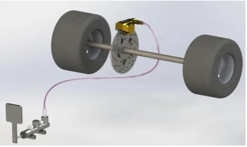
ii) Braking System:
A brake is a mechanical device that inhibits motion by absorbing energy from a moving system. It is used for slowing or stopping a moving vehicle to prevent its motion, most often accomplished by means of friction. Hydraulic brake torque is commanded by application of the brake pedal from the driver [6]. The hydraulic disc brakes were used in go kart as they are more efficient than drum brakes and compact in size. In a hydraulic brake system, when the brake pedal is pressed, a pushrod exerts force on the piston in the master cylinder, causing fluid from the brake fluid reservoir to flow into a pressure chamber through a compensating port [7]. This results in an increase in the pressure of the entire hydraulic system, forcing fluid through the hydraulic lines toward one or more calipers where it acts upon one or more caliper pistons sealed by one or more seated O-rings (which prevent leakage of the fluid). The brake caliper pistons then apply force to the brake pads, pushing them against the spinning rotor, and the friction between the pads and the rotor causes a braking torque to be generated, slowing the vehicle. Main components of the system are ventilated discs, master cylinders, brake calipers, hydraulic lines, brake fluid.
Figure 3. Braking system of Go-kart
iii) Wheel Assembly:
We used 22 inches diameter slick tires as they provide better grip and traction force from the track to achieve optimum torque and maximum speed. These tires are reliable and standard for racing vehicle, and they are available at reasonable cost. The following mentioned angles were calculated while designing to ensure optimal performance of go kart.
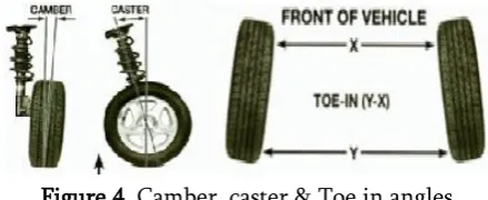
Camber Angle: The camber angle is the angle between the vertical reference (perpendicular to road surface) and the line that runs through the center of wheel [8]. Positive camber is the inclination of the wheel plane outwards from the vertical. The wheel shown (figure 6.) would roll to the left because of the 'lateral camber force', if a right-hand counter-weight did not restore the balance (i.e. the direction straight ahead) wheel is inclined outwards (Figure 6) and negative, when inclined inwards. When a vehicle is loaded with two or three persons, a slightly positive camber would be useful on passenger cars to make the tyres roll as upright as possible on the slightly transverse-curved road surface and give more even wear and lower rolling resistance [9].
Figure 4. Camber, caster & Toe in angles
King Pin Inclination: It is the angle between the vertical reference and the line that runs through the center of king pin.
Toe angle: Deviation of the wheels from straight ahead position. In case the wheels are pointing inward it is called toe in and if outward then toe out. In our case toe angle is 0 degree.
iv) Power Train:
Power train consists of all the elements that are required to transmit the power produced by the engine to the wheels. The Go kart is a simple chain driven vehicle. We used a 190cc, 4.5 bhp Briggs and Stratton OHV intek model which is a four stroke engine. Our kart is a double wheel drive which means both the wheels are powered helping in straight track. But we also have an option to power just one wheel by having a break in the driven shaft which are joined by a coupler, which can be joined or removed according to the requirement. The power is transmitted from engine to centrifugal clutch and thus to rear axle by chain drive system. Both clutch and axle sprockets are removable and their ratio has been carefully selected according to track configuration.
Table 1. Engine Specification
HP 4.5HP
Displacement 190 cc
Muffler Super Lo-Tone
Fuel Capacity 4.0 qt (3.79 L)
Lube Oil Capacity oz. (L) 20 oz. (0.60 L) Dry weight lb. (kg) 34 lb. (15.31 kg)
OHV Yes
Foam Filter Yes
Splash Lubrication Yes
Ignition Magnetron
Figure 5. Powertrain of Go-kart
B. Driver Ergonomics
Comfort is the first thing that all consumers want in a vehicle, thus it becomes an important aspect of the overall design scheme to achieve so. Real time data was collected for male & female after which 90% of the population was considered to be comfortably seated for the vehicle’s designing. Anthropometric data was considered to design the pedals position adjustments correctly.
According to the age and height range considered. [10]
Figure 6.Human body diagram depicting various measurements
Table 2. Anthropometric data
MALES FEMALES
Measurements
(Inches)
1 Forward Grip
2 Elbow Height 47 44 40 43 40 37
3 Hip Height 39 36 33 36 33 30
4 Fingertip
Height 29 26 23 27 25 22
5 Shoulder
Height 61 57 52 56 52 48
6 Eye Height 72 67 63 64 60 56
7 Stature 74 69 65 68 64 60
8 Vertical
Reach Grip 87 82 77 81 76 71
II.
CHASSIS ANALYSIS AND DEVELOPMENT
One of the main objects of this project was to develop a new chassis design thus reducing the weight of the chassis and meeting all the safety regulations. The function of a chassis in a go kart is to protect the driver and support all operator control systems, engine and other systems of the vehicle. In order to accomplish high quality, homogeneous welded joints and high strength, MIG welding was used. The use of the MIG welding benefited as it has high deposition rate as compared to electric arc welding. Also, minimum post weld cleaning is required along with less requirement of highly skilled worker. This resulted in the increase of product lifetime of the vehicle. The designing of the chassis was an iterative process so as to make the chassis design suitable according to the various factors. The final design of the chassis is shown in figure 9. along with the measurements.
Figure 7. Chassis design
A. Material Selection
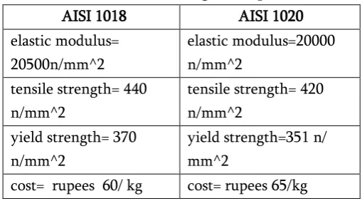
The amount of carbon in steel is important to determine the strength, hardness, and machining characteristics. Material selection of the frame plays an important role in providing desired strength, endurance, safety and reliability of the vehicle [11]. The material used for chassis could be from various grades of steel or aluminium alloys. The main component of steel is carbon which increases the hardness of material of chassis. Aluminium alloy is expensive than steel so mainly steel is used to construct the chassis [12]. The chassis is affected by many forces acting on it whether it’s in static condition or in dynamic condition. So, the strength requirements along with weight minimization play a crucial role for the proper balance of the vehicle. Therefore the following research was conducted, shown in table 3, for the material selection for the chassis.
Table 3. Material Strength Comparisons
AISI 1018 AISI 1020
elastic modulus= 20500n/mm^2
elastic modulus=20000 n/mm^2
tensile strength= 440 n/mm^2
tensile strength= 420 n/mm^2
yield strength= 370 n/mm^2
yield strength=351 n/ mm^2
cost= rupees 60/ kg cost= rupees 65/kg
Two materials were considered for the frame based on rule set and the ease of procurement. AISI 1018 and AISI 1020 comparative study of their cost and properties was undertaken to firm up the selection. The AISI 1018 was selected for its high tensile strength and yield strength, keeping in mind the price of the material as well. The circular cross section pipe was used and of specification mentioned below in the table 4.
Table 4. Specifications of the chassis pipe
Yield Strength 370 N/Mm^2
Thermal Expansion Coefficient 11/K
Thermal Conductivity 50 W/ (M-K)
Round Pipes of Inner Diameter 22M
B. Chassis Analysis
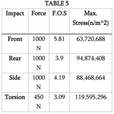
After the selection of the material, the design of the chassis was analyzed using the Solidworks Software. As no suspension system is provided to our vehicle, it is necessary to analyze torsional stresses acting on our vehicle. Since there might be ups and downs in vehicle travelling path, the chassis would get affected by many forces while in rest and motion [13]. Various analyses were made using Solidworks Simulation Express such as static, impact, and torsional analysis. The loads of different intensity were applied on the chassis from different angles and sides. The following table 5 depicts the values of the forces, factor of safety and maximum stresses.
TABLE 5
Impact Force F.O.S Max.
Stress(n/m^2)
Front 1000 N
5.81 63,720,688
Rear 1000
N
3.9 94,874,408
Side 1000
N
4.19 88,468,664
Torsion 450 N
3.09 119,595,296
i)Front Impact Loading:
Vehicle under a head-on collision undergoes through a severe impact load at front. So, by fixing the back of chassis, force is applied on the front part of the vehicle.
The factor of safety achieved is 5.81 which is acceptable.
Figure 8. Deformation of chassis when force is applied in the front of the chassis
ii) Back Impact Loading:
The back end of the vehicle is tested by applying load at it, by fixing the front end.
The factor of safety achieved is 3.9, which is acceptable.
Figure 9. Deformation of chassis when force is applied at the rear of the chassis
iii) Side Impact Loading:
In this impact loading, one side of the chassis is fixed and the load is applied on the other end.
Figure 10. Deformation of chassis when force is applied on the side of the chassis.
iv) Torsional:
Rear and front portion of the vehicle at wheel are fixed and torsional load is applied at portion of front wheels.
The factor of safety achieved is 3.09 which is acceptable.
Figure 11. Deformation of chassis due to torsion.
III.
ADJUSTABLE SYSTEMS DEVELOPMENT
A. Adjustable Camber System
The goal was to minimize the number of processes involved in fabricating the adjustable mountings as well as not to add any additional sub-assemblies thereby maintaining the desired weight of vehicle. For this purpose, the adjustable mountings were designed on the PLM software – Solid Works. To check the feasibility of these mountings, replicas were created which were tested for easy movements without any restraints. After successful testing these replicas were made using mild steel into workable components. While manufacturing the adjustable camber system, the position of front uprights was kept in mind. The camber angle was adjusted with the
help of eyeballs rather than screws or bolts providing the required flexibility. When the eyeballs are loosened, the camber gets inclined toward the x-axis keeping ground as reference. These very eyeballs when tightened up, the camber moves back to its position, thus inclining towards the y-axis. This results in improved vehicle dynamics and increasing its load carrying capacity. Adjustable camber settings allow changing the camber angle of the vehicle with the help of movement of rod ends on the mounting. The different camber angles required vary according to the different race track conditions.
Figure 12. (a) Camber angle is zero (b) Camber angle is five degrees
B. Adjustable engine mounting
used both for competition as well as for amusement park purposes as it gives a scope for accommodating different sized engines which are generally used in go-karts.
Figure 13. Engine mounting plate with slots
C. Adjustable Pedal System
The adjustable pedal system helps to accommodate people with different height. For this feature, proper calculations were carried out based on anthropometric data. On the basis of these calculations, a detailed design was made using Solidworks software. Then we started with the fabrication of the adjustable peddle system. A base plate was taken as per the dimensions required for the pedal system. Grooves were marked and then drilled. This plate was then welded on the chassis, upon which pedals were installed with the help of lock nuts. This enabled the pedals to move forward or backward, thereby making the kart accessible to a larger number of people having different height.
Figure 14. (a) Pedals are closer (b) Pedals are farther
IV.
CONCLUSIONS
The three systems - adjustable camber setting,
arrangement were installed in the go-kart in place of the conventional systems. These newly developed systems, although being simplistic in their physical structure, were successful in achieving the main objective of fabricating a go-kart which is drivable by majority of the people having different height and age without affecting the safety parameters and dynamics of the vehicle. The material selected for manufacturing was selected after comprehensive analysis hence keeping the gross weight of the vehicle as low as possible.
V.
REFERENCES
[1]. Roberto Lot and Nicola Dal Bianco.2015.Lap time optimisation of a racing go-kart, Vehicle System Dynamics, International Journal of Vehicle Mechanics and Mobilit ISSN: 0042-3114 DOI: 10.1080/00420042-3114.2015.1125514 [2]. Yunhe Yu and Saravanan M. Peelamedu. 2001.
Automotive Vehicle Engine Mounting Systems: A Survey, Journal of Dynamic Systems,
Measurement, and Control. DOI:
10.1115/1.1369361
[3]. 2005 CIK-FIA Technical Regulations
[4]. Allan Bonnick, "Velocity and acceleration, speed" in Automotive Science and Mathematics, First edition published by Butterworth Heinemann, 2008.
[5]. Ankit Gupta, Rohan Divekar and Mohit Agrawal .2010.Autonomous Parallel Parking System for Ackerman steering four wheelers, Computational Intelligence and Computing Research (ICCIC), IEEE International Conference. DOI: 10.1109/ICCIC.2010.5705869
[6]. S. R. Cikanek and K. E.
Bailey.2002.Regenerative braking system for a hybrid electric vehicle, American Control
Conference (IEEE Cat. No.CH37301).
DOI:10.1109/ACC.2002.1025270
Power and Propulsion Conference DOI: 10.1109/VPPC.2009.5289726
[8]. HIGUCHI & H. B. PACEJKA.2007. The Relaxation Length Concept at Large Wheel Slip and Camber, Vehicle System Dynamics: International Journal of Vehicle Mechanics and Mobility DOI: 10.1080/00423119708969644 [9]. Prof. Dipl.-Ing. Jornsen Reimpell, "Wheel travel
and elastokinematics" in The Automotive Chassis: Engineering Principles, Second edition published by Butterworth-Heinemann, 2001 [10]. A. R. Tilley and H. D. Associates," Vehicular
Accommodation" in The Measure of Man and Woman: Human Factors in Design, John Wiley & Sons, 2002.
[11]. DAVID A. CROLLA ,"Structural Design" in AUTOMATIVE ENGG., First edition published by Butterworth-Heinemann, 2009
[12]. Koustubh Hajare, Yuvraj Shet and Ankush Khot, "A Review Paper On Design And Analysis Of A Go-Kart Chassis", IJETMAS, ISSN 2349-4476.
[13]. Caroll smith, "External Aerodynamics" in TUNE