Journal of Engineering Sciences, Volume 6, Issue 2 (2019), pp. E 11–E 16 E 11 JOURNAL OF ENGINEERING SCIENCES
ЖУРНАЛ ІНЖЕНЕРНИХ НАУК
ЖУРНАЛ ИНЖЕНЕРНЫХ НАУК
Web site: http://jes.sumdu.edu.ua DOI: 10.21272/jes.2019.6(2).e2 Volume 6, Issue 2 (2019)
Braking Pattern Impact on Brake Fade in an Automobile Brake System
Towoju O. A.
Adeleke University, P.M.B. 250, Ede-Osogbo Rd., Ede, Osun State, Nigeria
Article info:
Paper received:
The final version of the paper received: Paper accepted online:
January 1, 2019 April 4, 2019 April 10, 2019
*
Corresponding Author’s Address:
[email protected]
Abstract. The importance of brake systems in automobiles cannot be overemphasized. Brakes are used in speed control of vehicles and do so by the conversion of kinetic energy into thermal energy. Better stopping performance has favored the disc brake system over the drum brake system and has found wide application in high-performance vehicles. Brake fade, caused by thermal overload has placed a limit on the permissible temperature at which braking systems can function, and it is the task of designers to ensure that this is avoided. However, even with a good design, panic braking at high speeds could lead to high-temperature values. This study is thus undertaken to numerically investigate the effect of selected braking patterns on temperature growth which could lead to brake fade in a disc brake system for a 2 200 kg car moving at a velocity of 40 m/s whose velocity is expected to be reduced to 4 m/s after five seconds with two matches of the brake for a seconds’ interval. The peak temperature attained in the system during braking was observed to be different for the different braking patterns, and the best-suited pattern was the 1s-1s-3s with peak temperature values below 600 K.
Keywords: automobile, brake fade, disc brake, temperature distribution.
1
Introduction
Brakes are mechanical devices that restrain motion and does so by the absorption of energy from a moving system which is achieved by friction, pumping on electromagnetic means.
The importance of brakes in automobiles cannot be over-emphasized; it is used for its stoppage and speed control. Automobiles generally use the friction type of braking system which consists of a group of mechanical, hydraulic and electronic activated components.
2
Literature Review
Brakes are basically devices used in the conversion of kinetic energy to thermal energy [1, 2]. Automobiles generally use the friction type of braking system which consists of a group of mechanical, hydraulic and electronic activated components. The automobile friction type braking system is either the disc or the drum system [3], and the choice of one is dependent on the purpose it is required to fulfill. The all-disc braking system is made use of in high-performance vehicles, and rarely will one see the drum braking system used at the front wheels of modern vehicles except on the rear wheels.
Automotive disc brakes are usually made of grey iron [2, 4, 5], and uses calipers to squeeze a pair of pads against a moving/rotating disc thereby causing its
retardation as a result of friction. The disc brake is favored over the drum brake system because of its better stopping performance attributable to its better heat dissipation rate, and its better recovery from immersion into liquid [6]. For better heat tolerance, disc brakes can also be manufactured from ceramic composites. However, the impact of cost has limited its use to exotic cars.
Brake fade is caused by overheating of the brake system and results in a temporary reduction or complete loss of brake power, and it is to be avoided [8]. The heat storage and dissipation capacity of the brake system are of upmost importance in the prevention of brake fade which is caused by thermal overload especially during a single stop or repeated stops from a high speed and/or high load condition [4, 6, 8–12].
E 12 MECHANICAL ENGINEERING: Computational Mechanics [2, 13, 18, 19]. To ensure fast cooling through forced
convection, brake discs are usually also ventilated [16, 20], however, ventilation of the brake disc can result into the induction of an uneven temperature distribution field in the disc [21], and by extension Judder effect [21, 22].
Generally, brake pads could be effective up to a temperature of about 600 K [11, 14, 22], while for racing vehicles, the effective operating temperature of the brake pads without fading can be as high as 900 K [14]. Repeated thermal stresses caused by high temperature usually results into the development of hot spots [24, 25] which subsequently can result into heat cracks on the brake disc surface [16, 19, 26, 27].
Asides the vehicle weight, velocity, and time required to bring the vehicle to a halt or reduced velocity, the braking pattern also contributes to the inception of brake fade. This study is thus focused on the impact of braking pattern on brake system fade using six different scenarios.
3
Research Methodology
The thermal distribution of a disc braking system was determined numerically by modeling a brake assembly fitted to a vehicle of total mass 2 200 kg (mass of vehicle plus payload) moving at a velocity of 40 m/s (144 km/hr). The vehicle is to be brought to a speed of 4 m/s in 5 s after the first march of the brake pedals, which is expected to be twice with a time lapse of 1 s in-between the marches.
The model as developed by COMSOL Multiphysics for a disc brake system geometry and material properties was made. The heat transfer module was employed in the numerical solution.
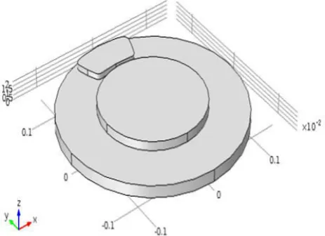
It was assumed that there is no skidding, and all the kinetic energy at the surface of the disc brake is transferred to thermal energy in the brake system, and also the pressure distribution generated by the brake pad on the disc brake surface is uniform. The designed disc brake system is shown in Figure 1.
Figure 1 – The designed disc brake dimension
The deceleration power of the brakes while neglecting drag and any other losses outside the brakes is the negative value of the time derivative of the vehicle’s kinetic energy.
(1)
(2) where is the deceleration power; is the vehicle mass; V is the vehicle velocity.
The total frictional heat source of the brakes is equivalent to the brake deceleration power, that is
(3) And since a standard car fitted with an all-disc brake system has eight brake pads, the frictional heat source at each of the brake pads is given by
(4) The frictional heat source per unit area is related to the contact pressure between the pad and disc according to the equation:
(5) The thermal energy generated at the boundary between the brake pad and the disc is dissipated by convection and radiation, and for this study, the rotation of the disc is modeled as convection in the disc, and the local disc velocity vector is given as
(6) The thermal properties of the disc brake system used for this study are shown in Table 1, and the geometry dimension is as stated in Table 2.
The disc brake was meshed using the free triangular 1, and the parameters are stated in Table 3.
The temperature distribution in the disc brake system were then determined numerically for braking patterns of first march interval, release period, and second march interval as follows, s: 0.5–1.0–3.5, 1.0–1.0–3.0, 1.5–1.0– 2.5, 2.0–1.0–2.0, 2.5–1.0–1.5, and 3.0–1.0–1.0.
Journal of Engineering Sciences, Volume 6, Issue 2 (2019), pp. E 11–E 16 E 13
Table 1 – Thermal properties of brake system
Material Density (kg/m3)
Heat capacity at constant pressure,
J/(kg·K)
Thermal conductivity, W/(m·K)
Surface emissivity
Disc 7 870 449 82 0.28
Pad 2 000 935 8.7 0.80
Air 1.170 1 100 0.026 –
Table 2 – Brake system dimensions, m
Part Radius Thickness Disc 0.140 0.013 Wheel bearing 0.080 0.010
Table 3 – Disc brake mesh parameters
Element size (max) 0.00980 Element size (min) 0.00042 Maximum element growth rate 1.35 Factor of curvature 0.30 Narrow region resolution 0.85
4
Results and Discussion
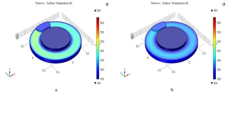
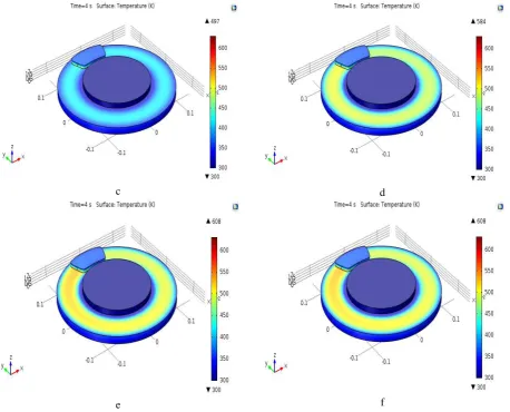
The surface temperature was seen to vary with time and position on the disc and brake pad, leading to a temperature distribution and this is evident from the surface distribution plot for the selected braking patterns after a time period of two seconds of the brake application depicted in Figure 2.
The peak temperature value was observed to be at the tip of the brake pad during the period of the brake application.
These temperature values at the tip of the brake pad are plotted against time for each of the investigated braking patterns and depicted as shown in Figure 3.
The different braking patterns result in different temperature values. The peak temperature values for the different patterns were observed to be the same for the first 0.3 s of the brake application, and this was so because an average retardation value was assumed
throughout the braking period, and the minimum first match period was 0.5 s.
The peak temperature values for each of the different braking patterns were also observed to occur before the brake is unmatched, and is a function of the time of a match. With the notion of brake fade set in at a temperature above 600 K [9, 14], the best fit braking pattern to avoid brake fade was observed to be as follows, s: 1.0–1.0–3.0, and this is closely followed by the braking pattern 0.5–1.0–3.5.
The temperature of the brake pad two seconds after the braking and attainment of the required velocity; 4 m/s, is also a function of the braking pattern as depicted in Figure 3, while it is highest for 1.0–1.0–3.0 s, it is least for 3.0–1.0–1.0 s. This is attributable to the fact that after the attainment of the peak temperature during the braking pattern 3.0–1.0–1.0 s, the remainder of the braking match period was used in the cooling of the brake pad as against for the other patterns with two separate peak values.
E 14 MECHANICAL ENGINEERING: Computational Mechanics
c d
e f
Figure 2 – Brake system surface temperature distribution for the following patterns, s: a – 0.5–1.0–3.5; b – 1.0–1.0–3.0; c – 1.5–1.0–2.5; d – 2.0–1.0–2.0; e – 2.5–1.0–1.5; f – 3.0–1.0–1.0
Figure 3 – Brake pad tip temperature
5
Conclusions
The thermal energy generated during braking and the subsequent temperature rise and distribution on the disc brake system have been shown to be dependent on the braking pattern. If need be, for repeated quick braking,
the interval should be such that the first match does not lead to excessive heat generation.
Journal of Engineering Sciences, Volume 6, Issue 2 (2019), pp. E 11–E 16 E 15
References
1. Shi, S. (2016). Automobile Brake System. Savonia University of Applied Sciences.
2. Alnaqi, A. A., Kosarieh, S., Barton, D. C., Brooks, P. C., Shrestha, S. (2018). Material characterisation of lightweight disc brake rotors. Proceedings of the Institution of Mechanical Engineers, Part L: Journal of Materials Design and Applications, Vol. 232(7), pp. 555–565.
3. Introduction to Braking System. SAE Tezpur University, http://www.tezu.ernet.in/sae/Download/Brakingsystem.pdf.
4. Maleque, M. A., Dyuti, S., Rahman, M. M. (2010). Material selection method in design of automotive brake disc. Proceedings of the World Congress on Engineering, Vol. 3, London, UK.
5. Maluf, O., Angeloni, M., Milan, M., Spinelli, D., Waldek, W., Bose, F. (2004). Development of materials for automotive disc brakes. Pesquisa Technol Minerva, Vol. 2, pp. 149–158.
6. Ganaway, G. (2011). Air disc brake production. NDIA Tactical Wheeled Vehicles Conference. Monterey, California, USA.
7. Radhakrishnan, C., Yokeswaran, K., Kumar, N. M., kumar.S. B., Gopinath.M., Inbasekar, B. (2015). Design and optimization of ventilated disc brake for heat dissipation. International Journal of Innovative Science, Engineering and Technology, Vol. 2(3), pp. 692–694.
8. Harshal, S. S. (2017). Structural analysis of disc brake rotor for different materials. International Research Journal of Engineering and Technology, Vol. 4(7), pp. 2129–2135.
9. Jerew, B. Understanding Brake Fade and How to Prevent It. Retrieved from https://www.thoughtco.com/how-to-prevent-brake-fade-4152020.
10. Talati, F., Jalalifar, E. S. (2009). Analysis of heat conduction in a disk brake system. Heat Mass Transfer, Vol. 45, pp. 1047– 1059.
11. Gowtham, S., Manas, M. B. (2015). Elimination of brake fade in vehicles by altering the brake disc size (a concept).
International Journal of Innovative Research in Science, Engineering and Technology, Vol. 4(11), pp. 11349–11352.
12. Adamowicz, A., Piotr, G. (2011). Influence of convective cooling on a disc brake temperature distribution during repetitive braking. Applied Thermal Engineering, Vol. 31(14), pp. 2177–2185.
13. Grieve, D. G., Barton, D. C., Crolla, D. A., Buckingham, J. T. (1997). Design of a lightweight automotive brake disc using finite element and Taguchi techniques. Proceedings of the Institution of Mechanical Engineers. Part D: Journal of Automobile Engineering, Vol. 212(4), pp. 245–254.
14. Streit C. Solving Brake Fade in Performance Brake Systems. Retrieved from https://alconkits.com/drmassets/Brake-Fade-Solved.pdf.
15. Zaini, D. (2014). Braking system modeling and brake temperature response to repeated cycle. Mechatronics, Electrical Power, and Vehicular Technology, Vol. 5, pp. 123–128.
16. Kudal, G. B., Chopade, M. R. (2016). Heat Transfer characteristics of ventilated disc brake rotor with diamond pillars – a review. International Journal of Current Engineering and Technology, Vol. 4, pp. 219–222.
17. Khivsara, S., Bapat, R., Lele, N., Choudhari, A., Chopade, M. (2015). Thermal analysis and optimisation of a ventilated disk brake rotor using cfd techniques. International Journal of Emerging Technology and Advanced Engineering, Vol. 5(7), pp. 59– 64.
18. Dahm, K. L., Black, A. J., Shrestha, S., Dearnley, P. A. (2009). Plasma Electrolytic Oxidation treatment of aluminium alloys for lightweight disc brake rotors. IMechE Conference on Braking, pp. 53–60.
19. Baskara, S. P., Muthuvel, A., Prakash, N., Stanly, W. L., (2015). Numerical analysis of a rotor disc for optimization of the disc materials. Journal of Mechanical Engineering and Automation, Vol. 5(3B), pp. 5–14.
20. Choi, B. K., Park, J. H., Kim, M. R. (2008). Simulation of the braking condition of vehicle for evaluating thermal performance of disc brake. Proceedings of KSAE Autumn Conference, pp. 1265–1274.
21. Belhocine, A., Cho, C.-D., Nouby, M., Yi, Y. B., Abu Bakar, A. R. (2014). Thermal analysis of both ventilated and full disc brake rotors with frictional heat generation. Applied and Computational Mechanics, Vol. 8, pp. 5–24.
22. Lee, S., Yeo, T. (2000). Temperature and coning analysis of brake rotor using an axisymmetric finite element technique. Proc. 4th Korea-Russia Int. Symp. on Science and Technology, Vol. 3, pp. 17–22.
23. Gao, C. H., Lin, X. Z. (2002). Transient temperature field analysis of a brake in a non-axisymmetric three dimensional model.
Journal of Materials Processing Technology, Vol. 129, pp. 513–517.
24. Altuzarra, O., Amezua, E., Aviles, R., Hernandez, A., (2002). Judder vibration in disc brakes excited by thermoelastic instability. Engineering Computations, Vol. 19(4), pp. 411–430.
25. Jang, Y. H., Ahn, S. H, (2007). Frictionally-excited thermoelastic instability in functionally graded material. Wear, Vol. 262, pp. 1102–1112.
26. Yamabe J., Takagi, M., Matsui, T., Kimura, T., Sasaki, M. (2002). Development of disc rotor for trucks with high thermal fatigue strength. Japan SAE Paper, 4017.
E 16 MECHANICAL ENGINEERING: Computational Mechanics
УДК 629.017
Вплив схеми гальмування на ефективність гальмівної системи автомобіля
Товоджу О. А.
Університет Аделеке, P.M.B. 250, шлях Еде-Осогбо, м. Еде, штат Осун, Нігерія
Анотація. Важливість гальмівних систем в автомобілях не може бути переоцінена. Гальма
використовуються для регулювання швидкості транспортних засобів і працюють за рахунок перетворення кінетичної енергії у теплову. Краща зупиняюча дія системи дискових гальм порівняно з барабанними
гальмами призвела до їх широкого застосування у високоякісних транспортних засобах. Зниження гальмівної
здатності, викликане тепловим перенавантаженням системи, накладає обмеження на допустиму температуру, за якої може ефективно функціонувати гальмівна система. Тому актуальною є проблема уникнення цього негативного ефекту. Однак, навіть при достатньо гарній конструкції, часте гальмування на високих
швидкостях може призвести до появи високих температур. Таким чином, ця стаття спрямована на виконання
числового дослідження впливу обраних схем гальмування на зростання температури у системі, що може призвести до зниження її ефективності. Дослідження проводяться для автомобіля масою 2 200 кг, що
зупиняється за 5с, починаючи з граничної швидкості 140км/год і завершуючи 15км/год. Найбільша
температура, досягнута системою при гальмуванні, відрізняється для різних схем гальмування. При цьому як найкращу схему обрано модель «1 с –1 с – 3 с» з граничним значенням температури 327 °C.