Design & Implementation of Data Acquisition &
Controlling System Based on Free RTOS Platform
Miral M. Desai
Department of Electronics & Communication Engineering, CSPIT, CHARUSAT, Changa, Gujarat [email protected]
Jignesh J. Patoliya
Department of Electronics & Communication Engineering, CSPIT, CHARUSAT, Changa, Gujarat [email protected]
---ABSTRACT---Data acquisition and controlling (DAC) system refers to provide solution which is capable of making measurement and controlling external processes using variety of hardware and software. The proposed design and its implementation of DAC system based on the freeRTOS platform. The suggested system is used to monitor and control industrial applications. The proposed system is design on open source hardware Arduino platform in which freeRTOS Application programming Interfaces (APIs) is installed and configured. As part of the hardware, here three basic sensors are used as temperature sensor for measuring temperature, flame sensor as measuring the flame and ultrasonic sensor as measuring the water level in the tank. Buzzer and LEDs are used as the controlling devices for flame sensor, whereas motor is used as the controlling device for ultrasonic sensor. Here temperature sensor is used as monitoring device. The proposed system can justify the remote monitoring and controlling task through the network using the web browser. The proposed system continuously monitors the sensor values and displays it onto the web browser. If the sensor value is exceeds from the threshold values, it will take necessary controlling actions.
Keywords - Data Acquisition & Controlling, freeRTOS
--- Date of Submission: May 16, 2018 Date of Acceptance: June 23, 2018
---1.
I
NTRODUCTIONI
n today’s era of Industry, there will be a crucial requirement of measuring various parameters and also require monitoring and controlling those parameters for getting good quality of result. These essential parameters could be anything like temperature, distance, flow of liquid, pressure, quality and quantity of liquid, fire detection etc. All these parameters can be sensed by the different type of sensors which are connected with the main system. Sometimes it is required to keeping log and doing analysis of these parameters and has to take some necessary control action according to the specific behavior of this measured value. All these things can be happened if the system is associated very good quality of Data Acquisition & Controlling System. The DAC system should be fast enough & responsive. The suggested system is based on the freeRTOS platform. The reason to design the system based on the freeRTOS is as the number of sensors can be behave like a separate task and all these sensors can handle in form of multiple task at one particular time. The advantage of the system is it can utilize all the resources of the operating system. The system can be consider as reliable as particular task can be deleted or inserted in the run time of the system as system is working on the freeRTOS platform. In the proposed system one dedicated task is constantly running which is creating the webpage for getting the record of each and every sensor values. Webpage generating task will create two more tasks in which in one task, both the ultrasonic sensors constantly measure the level of the water in boththe tanks and display the measured value on to the webpage. Whereas in another task temperature sensor continuously measures the temperature value and display measured value on to the page. One more task which is fire sensor task is behaved as an interrupt task i.e. this task is executing at any moment of time. This task has the highest priority. As the interrupt task is executed, it will directly give the notification in form of blinking the led and activating the buzzer. The proposed system block diagram of the system is shown in the Fig.1.
Fig. 1 Proposed System Block Diagram
2.
O
BJECTIVETo make the system multitasking and utilized the resources effectively, the objective of the system is to design and implement Data Acquisition & Controlling System based on the freeRTOS.
3.
S
YSTEMR
EQUIREMENTSTo design the DAC system based on the freeRTOS, system must fulfill the following requirements.
3.1 Hardware Requirements
For designing the proposed system we require following hardware.
Arduino UNO Board
Ethernet Shield compatible with Arduino UNO Board
Ultrasonic sensors (2 Nos.) Temperature sensor Flame sensor Led & Buzzer DC Motor
3.2 Software Requirements
Following software requirement are require designing proposed system.
Arduino C HTTP Protocol
FreeRTOS Utility compatible in Arduino
4.
L
ITERATURER
EVIEW4.1 RTOS & freeRTOS
Operating system is the system program which is an interface between the hardware and application program. The common features of the operating system are Synchronization between the task, Multitasking, Inter Process Communication, Interrupt Handling and Memory Management. RTOS is the Operating System which produces the result in the real time. So RTOS is an OS which is used in real time application and in Embedded System which provides logically correct result according to said deadline. In RTOS, the efficiency of the result depends on the logical correctness and the time at which result is produced. General Purpose Operating System (GPOS) focuses on the amount of work done within the time frame, whereas RTOS focuses on the criticality of timeliness. Free RTOS is a free and open-source Real Time Operating System developed by Real Time Engineers LTD. Free RTOS is a real-time operating system kernel for embedded devices. Free RTOS is written by Richard Barry & Free RTOS Team. Free RTOS is a real time scheduler on top of which MCU applications can be built to meet their hard-real-time requirements. The advantage of the RTOS based system is, it is time critical system where most of the task is completed in time so that most of the deadly events are reduced. Basic features of freeRTOS Architecture are as follows [1]:
Idle Time Utilization Flexible Interrupt Handling Queue Management Interrupt service Routine Handler Task
Ideal Task Periodic Task Interrupt Task Semaphore Binary Semaphore Counting Semaphore Mutex
4.2 Task & Task States
FreeRTOS is flexible for executing unlimited numbers of tasks. But at a moment of time only one task is executed. A Task is defined as a sort of job or process which is executed in define deadline. Any specific task passed through different types of states like Ready, Running, Blocking and Suspend. Typical task states diagram is shown in Fig.2.
Fig.2 Task States [2]
In RTOS, Scheduler will decide which specific task is in which state. As described in Fig.2, the meaning of individual state of the task is as follows:
Running
o Task is actually executing.
Ready
o Task is ready to execute but a task of
equal or higher priority is running. Blocked
o Task is waiting for specific event. The
task will block until the delay period has expired.
Suspend
o This state is as same as blocking sate,
4.3 Arduino UNO Board & Arduino C
The Arduino UNO board is shown in Fig. 3. The Arduino UNO board is ATmega328 based microcontroller which is working on 16MHz frequency. The board consists of inbuilt ADC and USB connection port [3].
Fig. 3 The Arduino UNO board
The Technical Specification of Arduino UNO board is as follows [3]:
Microcontroller ATmega328 Operating Voltage 5V
Input Voltage (recommended) 7-12V Input Voltage (limits) 6-20V Digital I/O Pins 14 Analog Input Pins 6 DC Current per I/O Pin 40 mA DC Current for 3.3V Pin 50 mA Flash Memory 32 KB SRAM 2 KB EEPROM 1 KB Clock Speed 16 MHz
Arduino C is the derived programming language from C/C++ which contains in built hardware based libraries.
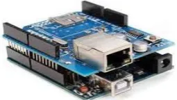
4.4 Ethernet Shield
Fig.4 Ethernet Shield
The arduino Ethernet Shield is used to connect the arduino to the internet. It enables arduino to send and receive data from anywhere in the world with an internet connection. The Ethernet Shield is based upon the W51000 chip, which has an internal 16K buffer. It has a connection speed of up to 10/100Mb. There is also an on-board micro SD slot. Setting it up is as simple as plugging the header pins from the shield into the arduino as shown in Fig. 4 [4].
4.5 Message Transfer Protocol – HTTP
HTTP stands for Hyper Text Transfer Protocol which is an application layer protocol. It is used mainly to send and receive information to the webpage and from the webpage. HTTP is the beginning of the Modern day internet which was invented around 1990s. HTTP is a connectionless protocol, thus the information sent between the client and server does not require a constant connection. The client can make request to any remote server and then the connection is terminated as soon as the request is met. Once the server is ready with the response connection is re-established and the data is transferred. Another feature of HTTP which adds to the versatility of the protocol is that any type of data can be sent over it. This makes the job of designer much easier as any data can be sent to any server without any external needs being met, thus HTTP is media independent. The server and client are aware of each other only when the data transfer between them is taking place, and the rest of the time they have no information about each other, so HTTP is a stateless protocol. A typical HTTP request will be look like [5]
String ("GET ") + /output.php + “HTTP/1.1\r\n"
+"www.iotnb.com" + host + "\r\n" + "Connection: close\r\n\r\n"
4.6 Scripting language to Design the Webpage – HTML
HTML stands for Hyper Text Markup Language. An HTML file is a text file containing small Markup tags. The markup tags tell the web browser how to display the page. An HTML file can be created using a simple text editor. An HTML file must have an .htm or .html file extension.
4.7 Ultrasonic Sensor
Fig. 5 Ultrasonic Sensor
To measure the level of water in water tank, Ultrasonic sensor is used in suggested system. The HC-SR04 is an ultrasonic ranging module. This economical sensor provides 2cm to 400cm of non-contact measurement functionality with a ranging accuracy that can reach up to 3mm. Each HC-SR04 module includes an ultrasonic transmitter, a receiver and a control circuit. Technical Specification of Ultrasonic sensor is as follows [6]:
4.8 Temperature Sensor
Fig. 6 Temperature Sensor
LM35 is a precision IC temperature sensor with its output proportional to the temperature (in oC). With LM35, temperature can be measured more accurately than with a thermistor. It also possesses low self-heating and does not cause more than 0.1 oC temperature rise in still air. The operating temperature range is from -55°C to 150°C. The output voltage varies by 10mV in response to every oC rise/fall in ambient temperature, i.e., its scale factor is 0.01V/ oC [7].
4.9 Flame Sensor
Fig. 7 Flame Sensor
As shown in the Fig.7, The Flame sensor is sensitive to the flame and radiation. It can detect ordinary light source in the range of a wavelength 760nm-1100 nm. The detection distance is up to 100 cm [8].
5.
S
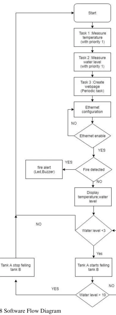
OFTWAREE
NVIRONMENTThe whole software environment is created using Arduino C language and freeRTOS utility of Cortex M3 compatible with Arduino. The detail software flow diagram for suggested system is shown in Fig. 8.
Fig. 8 Software Flow Diagram
6.
E
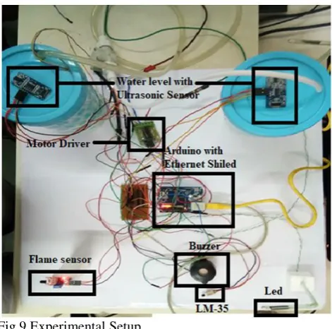
XPERIMENTALS
ETUPFig.9 Experimental Setup
7.
T
ESTR
ESULTS&
D
ISCUSSIONTest results of the proposed system are discussed in form of acquisition and controlling. Fig.10 & Fig.11 describes the result of acquisition system which shows the result of measured value of temperature, water level & flame in form of the fire using temperature sensor, ultrasonic sensor and flame sensor respectively. Fig.12 describes the controlling as if fire exceeds from certain value, its turn on leds and buzzer as alarm. Fig. 13 describes status of tank A and tank B. It shows that water level of tank A exceeds from certain values, so its shows tank A is full where as tank B is empty. Fig. 14 describes the status of tank when tank A start to fill tank B.
Fig. 10 Acquisition Result of Temperature & water level
Fig. 11 Acquisition Result of Flame Sensor
Fig.12 Status of Buzzer & LED when fire exceeds from certain value
Fig.13 Status of tank before water level exceeds
Fig.14 Status of tanks after water level exceeds
8.
C
ONCLUSIONseparate task. As a part of monitoring, the measured value of individual sensor can be display on the web server. Sensor value can be controlled in form of the leds, buzzer and motor. Proposed system can be enhanced in form of the inter process communication, where semaphore, mutex and queue features of freeRTOS can be add to create the synchronization in the tasks.
REFERENCES
[1] Real Time Engineers Ltd., Using the FreeRTOS Real Time Kernel, ARM Cortex-M3 Edition,2010
[2] D. Rinku & M. Arshad, “Design & Implementation of freeRTOS Based Online Data Acquisition And Controlling System Using Cortex M3core”,
International Journal of Engineering Science &
Advanced Technology, Volume 3, Issue 5, 2013, pp.
259-263
[3] Homepage on Arduino UNO [Online] Available https://datasheet.octopart.com/A000066-Arduino-datasheet 38879526.pdf
[4] Homepage on Arduino Ethernet Shield [Online] Available
http://www.farnell.com/datasheets/1682241.pdf
[5] Homepage on HTTP [online] Available. https://www.tutorialspoint.com/http/http_parameters. htm
[6] Homepage on Ultrasonic Sensor [Online] Available http://centmesh.csc.ncsu.edu/ff_drone_f14_finals/Se nsor1/files/hcsr04.pdf
[7] Homepage on Temperature Sensor [Online] Available
https://www.engineersgarage.com/electronic-components/lm35-sensor-datasheet