Int. J. Advanced Networking and Applications
Volume: 04 Issue: 05 Pages: 1760-1765 (2013) ISSN : 0975-0290 1760
Comparison of Different Methods to identify
wormhole attacks in MANETS
S.Seethalakshmi1
1Asst.Professor, Thiagarajar School Of Management, Madurai 625005, India.
Dr. K. Chitra Manikandan2
2Asst.Professor, Govt. Arts College, Melur, Madurai.
---ABSTRACT- ---A self-organized network without a central coordinator that changes its topology frequently is called a M---ANET. Two faraway nodes in a MANET seem to give an impression that they are situated close to each other due to the presence of malicious nodes referred to as worm-hole nodes. Due to the dynamic change in topology finding route is very difficult. Some nodes misbehave as they participate in route establishment phase but refuse to forward the data packets to conserve their own energy. In this paper we are going to compare three different methods (PT method, WAP method, TWOACK method) to detect misbehaving nodes. Simulation is carried through NS2 and the results of misbehaving nodes are compared and tabulated.
Keywords : measures, DSR protocol, PT method, TWOACK scheme, Wormhole Attack prevention(WAP)
--- Paper submitted: 08.02.2013 Revised: Date (only if applicable), Accepted: 20.03.2013
---
I. INTRODUCTION:
A worm hole is an attack on the routing protocol of a Mobile Ad-hoc Network (MANET). In a wormhole attack, two or more colluding nodes create an illusion that two remote regions of a MANET are directly connected through nodes that appear to be neighbors but are actually distant from one another. This shortcut is created by connecting the respective neighbors through a secret communication channel. A wormhole thus allows an attacker to create two attacker-controlled choke points which can be utilized by the attacker to degrade or analyze traffic at a desired time. Our focus on this paper is to detect the worm hole attacks based on various metrics and finding out the strength of the attack in the MANETS. In our paper Section 2 describes the placement of wormholes with different variations. Section 3 describes the various metrics to measure the strength of the wormholes with their analysis. Section 4 describes the simulation study of the worm holes and their strengths using three different proposed methods namely PT method, WAP method and TWOACK method. Section 5 gives the summary and conclusion.
II. PLACING THE WORMHOLES IN
DIFFERENT MODES:
In this section we present different variations of a wormhole attack.
2.1 In-band and out-of-band wormholes
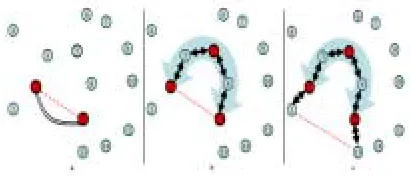
In an out-of-band wormhole, the colluder nodes establish a direct link between the two end-points of the wormhole tunnel in the network. This link is established using a wired link or a long-range wireless transmission. Figure 1a shows an out-of-band wormhole established in a network by two colluding nodes. The wormhole attacker then receives packets at one end and directs the packets to be forwarded to the other end through the established link. The attacker can thus analyze and tamper a large amount of traffic through this link.
An in-band wormhole, on the other hand, does not use an external communication medium to develop the link between the colluding nodes. An in-band wormhole instead develops a covert overlay tunnel over the existing wireless medium. An in-band wormhole can be a preferred choice of attackers and can be potentially more harmful as it does not require any additional hardware infrastructure and consumes existing communication medium capacity for routing the tunneled traffic. Figure 1b shows an in-band wormhole developed over a wireless network using false OLSR messages. Nodes 2 and 11 create an illusion of being neighbors by sending false routing advertisements of a 1-hop symmetric link between the two nodes without the actual exchange of HELLO messages. This false link information is propagated to other nodes across the network via a broadcast of OLSR Topology Control (TC) messages. This false link information thus undermines the shortest path routing calculations attracting many end-to end flows by advertising incorrect shortest paths. The attracted traffic is then forwarded through a
tunnel with the
help of a third colluder node, node 5. This colluder node acts as an application-layer relay for wormhole traffic between the wormhole endpoints2.2 Self-contained and extended in-band wormholes We now describe two forms of in-band wormholes: extended in-band wormhole and self-contained in-band wormhole. An extended wormhole creates a wormhole that extends beyond the attackers forming the tunnel endpoints. A false link is advertised between two nodes that are not the attacker nodes. A potentially stealthier self-contained wormhole, on the other hand, advertises a false link between the attacker nodes themselves. Figure 1c presents an example of an extended wormhole. The attacker nodes 2 and 11 forming the tunnel. End points capture HELLO messages from nodes 1 and 13 and forward them through the relay node 5 to pass through the
tunnel to the other end. All subsequent OLSR control and data messages are forwarded in a similar fashion. This results in a false link between nodes 1 and 13 extending the wormhole beyond the endpoint nodes 2 and 11. Figure 1b presents an example of a self-contained wormhole, where the attacker nodes 2 and 11, forward their own HELLO messages to each other, or simply falsely report each other as neighbors by sending incorrect HELLO messages. The incorrect HELLO messages, further broadcast by TC messages, lead to advertisement of a false link between the two attacker nodes 2 and 11, developing a self-contained in-band wormhole.
III. MEASURES OF WORM HOLES TO FIND
THEIR STRENGTH:
There are different metrics to measure the strength of the wormhole present in a network. They are strength, path length difference, attraction, robustness and packet delivery ratio.
3.1 Strength:
It is the amount of traffic attracted by the false link advertised by the colluding nodes. The effectiveness of a wormhole attack is based on the amount of traffic that can be attracted by a wormhole. The larger the amount of attracted traffic, stronger can be the wormhole attack on the network traffic. We define the strength of a wormhole attack as the number of end-to-end paths attracted by the false link advertisement sent by the attackers. In other words, the strength of a wormhole is the number of end-to-end paths passing through the wormhole tunnel. 3.2 Difference in path length:
Another metric for a wormhole attack is the difference in the advertised path length and the actual path length. For instance, in Figure 1b the advertised path from 1 to 13 passes through the nodes 1, 2, 11, and 13, advertising a path length of 3 hops. However, the actual path from 1 to 13 passes through the nodes 1, 2, 3, 5, 8, 11, and 13, making the actual path of length 6 hops. This metric can be useful for the purpose of detection of the wormhole. Larger the difference between the actual path and the advertised path, more anomalies can be observed in the network.
Int. J. Advanced Networking and Applications
Volume: 04 Issue: 05 Pages: 1760-1765 (2013) ISSN : 0975-0290 1762
This metric refers to the decrease in the path length offered by the wormhole. If the attraction is small then the small improvements in normal path may reduce its strength. For instance, in Figure1b, before the wormhole attack, the path from node 3 to node 13 might pass through the nodes 3, 5, 8, 11, and 13.After the wormhole attack, the path passes through the nodes 3, 2, 11, and 13, decreasing the path length by 1 hop.
3.4 Robustness:
Robustness of a wormhole refers to the ability of the wormhole to persist without significant decrease in the strength even in the presence of minor topology changes in the network. The resilience of the wormhole to small changes of topology is based on the amount of attraction offered by the wormhole. If the attraction is small then small improvements in normal paths can result in nodes choosing alternative paths that do not pass through the wormhole link, thus decreasing the strength of the wormhole.
3.5 Packet delivery ratio:
This metric is a ratio which is the number of packets delivered to the total number of packets dispatched. This forms a basic metric to quantify the impact of intrusion.
IV. SIMULATION SCENARIO:
NS2 (version 2.34) network simulator is being used for simulation study. Total number of nodes tested is 50. Multiple topologies by changing the number of nodes from 15 to 50 are run though the simulation process. Multiple topologies are generated in a pseudo random manner. Random way point access model is taken as the base model for implementation. Since the performances of reactive routing protocols are better than proactive routing protocols, the metrics are analyzed through DSR, a reactive protocol. Considering some of the end points as wormholes, each time the simulation is carried out by changing the topological structure. The TABLE1 discusses simulation parameters with tested values.
4.1 Simulation Parameters Table 1
Parameter taken Actual approximate value
Number of Nodes 50
Area – X,Y 800m
Traffic simulation Model CBR Mobility Model RWP Access Routing Protocol Reactive DSR
Packet rate 4 .0
Packet size 128 bytes
Simulation time(Seconds) 1000
Transmission Range Around 50 metres
4.2 Results of Packet Delivery Ratio
PDR is the ratio of the total amount of packets received to the amount of packets sent. If the numbers of malicious nodes increase, then PDR decreases gradually. The higher mobility of nodes causes PDR to decrease.
---
PDR = data packets received / data packets sent ---
Three different methods are taken for the comparison in terms of packet delivery ratio and efficiency of producing the throughput. They are Path tracing Method, Two way Acknowledgement and the DSR .
4.2.1 Path Tracing (PT) Method:
Steps to detect the wormhole attacks using Path Tracing Method
Step 1: Nodes in a path computes RTT values based on
the time between the RREQ sent and RREP received. The RTT computation is based on its own clock.
Step 2: Compute per hop distance value using RTT value.
The computed per hop distance value and timestamp are stored in each packet header.
Step 3: These information are stored to identify the
wormhole link. Every node in a path computes per hop distance with its neighbor and compares it with the prior per hop distance. If the per hop distance exceeds the maximum threshold range, RTh, go to step 4.
Step 4: Check for the maximum count a link takes part in
Step 5: Mark the link as wormhole and the
node informs other nodes to alert the ne wormhole nodes are then isolated from the n
Fig2: Flow Chart of PT Algorith
The wormhole detection process is perform of route discovery to reduce overhead and proposal energy efficient. Per hop distance based on RTT value and it is stored in the p The next set of nodes in a path compute pe and compares it with prior per hop distance the maximum threshold range then the wo identified and then the frequent appearance path is counted. If that count also exceeds frequent appearance count then wormh confirmed. Then, corresponding node intim nodes about wormhole. Finally, the wormh isolated from the network.
4.2.2 WAP (Wormhole Attack Prevention) M In this section, we describe a method f wormhole attack called as Wormhole Atta (WAP). All nodes monitor its neighbors’ b they send RREQ messages to the destinati special list called Neighbor List. When a receives some RREP messages, it can detect wormhole attack among the routes. Once w is detected, source node records them in t Node List. Even though malicious node excluded from routing in the past, the n chance of attack once more. Therefore, information of wormhole nodes at the so prevent them taking part in routing again
Fig 3a) Neighbor node monitoring nodes
corresponding etwork. These network.
hm
med at the time d make to our e is calculated packet header. er hop distance e. If it exceeds rmhole link is e of a link in a the maximum hole attack is
mates all other hole nodes are
Method for preventing ack Prevention
behavior when ion by using a a source node t a route under wormhole node the Wormhole es have been nodes have a we store the ource node to
g of legitimate
Fig 3b) Neighbor node m nodes
Moreover, the WAP has the abili hidden and exposed attacks witho the link layer, it assumes that a n ongoing transmissions even if th intended receiver. This typically interface stay in the promiscuous all transmissions, which is less listening only to packets directe assume that radio links are bi-dire A is in transmission range of som transmission range of A. We f transmission range of a wormho normal node because more power detect.
4.2.3 TWOACK-scheme to detect 2ACK scheme importantly si mechanism Details of the 2AC scheme is a network-layer techni extenuate their effects. It can be on to existing path protocols for M and any other routing protocols. T a good behavior through the u acknowledgment bundle, termed is assigned a fixed path of two h contrary direction o the data tr scheme is a network-layer misbehaving links and to mitigat implemented as an add-on to ex for MANETs, such as OLSR. Th misbehavior through the use acknowledgment packet, termed is assigned a fixed route of two h opposite direction of the data tr scheme finds a good behavior th
monitoring of wormhole
ity of detecting both the out special hardware. At node can always monitor he node itself is not the y requires the network s reception mode during s energy efficient than ed to oneself. We also ectional; that is, if a node me node B, then B is in further assume that the ole node is similar to a rful transceiver is easy to
t wormholes
implifies the detection K Scheme. The 2ACK ique to find links and to implemented as an add-MANETs, such as OLSR
The 2ACK scheme finds use of a new type of
2ACK. A 2ACK bundle hops (three nodes) in the raffic path. The 2ACK
Int. J. Advanced Networking and Applications
Volume: 04 Issue: 05 Pages: 1760-1765 (2013) ISSN : 0975-0290 1764 type of acknowledgment bundle, termed 2ACK. A 2ACK
bundle is assigned a fixed path of two hops (three nodes) in the contrary direction of the data traffic path.
Notations and Assumptions:-
Data pkt Unique ID (DUID) : This is used to record the unique packet id of the sent Data packet.
Data pkt Sent Time (DST) : This records the time at which Data packet is sent.
Cpkts : This gives the total number of Data packets that are sent.
D2ACK : This records the Data packet ID for which the observing node has received the 2ACK packet i.e., 2ACK Packet is received for this Data packet.
2ART (2ACK Receive Time):This records the time at which the 2ACK packet is received.
R-CNT : It counts the total number of 2ACK packets that are received by the observing node.
Cmiss : It counts the total number of Data packets for which the 2ACK packet is not received.
Rmiss : It is the ratio of the Cmiss to the total number of Data packets sent, i.e., Cmiss/ Cpkts. At N1, each ID will remain on the record for ’t’ seconds, the respite for 2ACK reception. If 2ACK bundles matching to this ID arrive in front the timer exits, the ID will be took out from the records. Other than, the ID will be taken out at the last of its look out time separation and a counter called Cmis will be incremented. If N3 receives a data bundle, then calculated whether it wants to send a 2ACK bundle to N1. In order to cut down the extra path overhead reason by the 2ACK outline, only a divide the data bundle will be acknowledged verses multi hop bundle. Such a divide termed the acknowledgment proportion, Rack. By changing Rack, we can dynamically tune up the overhead of Many-Hop bundle transmissions. Client N1 remarks the behavior of link N2→N3 for a session of time Tobs. At the last of the session, N1 determines the proportion of losing 2ACK bundles as Cmis / Cpkts and compare it with a threshold Rmis. If the proportion is greater than Rmis, link N2→N3 is announced misbehaving and that particular link is being removed from the routing table. Since only a divide of the get data bundle are acknowledged, Rmis could simplify Rmis > 1- Rack neglect false alerts reason by such a
partially acknowledgment technique. Every client getting such a 2ACK packet remarks the link N2→N3 as misbehaving and sums it to the black records list of such misbehaving links that it controls. When a client begins its own data traffic after, it will avoid using such misbehaving connects as a part of its path.
2ACK: N3-N2-N1
Data Traffic
Fig4: Two-ACK Method
The graph1 shows the packet delivery ratio of various proposed methods to detect the malicious nodes. In that, X-axis specifies the percentage of misbehaving node and Y-axis specifies the packet delivery ratio. In X-axis the range is from 0 to 40% of misbehaving nodes and in Y-axis the range of PDR is from 0.5 to 1.Three different notations are used to show the results obtained for various algorithms proposed and the notations are also shown in graph1.
Graph 1: Variations in PDR with respect to the malicious node
Graph1 shows a comparative PDR of different algorithms proposed to identify the wormhole attacks. It is drawn on the basis of the various metrics of wormholes like strength, path length difference, attraction, robustness and PDR. Here we compare the PT algorithm with WAP and
TWOACK algorithm. When the fraction of malicious node occurrence is 0 all these algorithms give a good packet delivery ratio. If it is increased to 40% TWOACK gives 0.50, WAP gives 0.55, PT algorithm gives 0.65. PT algorithm produces 15% better performance than other techniques.
V. CONCLUSION:
In this paper we have analyzed various measurements which helped me to identify the wormhole attacks in terms of multiple parameters. A great emphasis to DSR protocol with Random way point Model is taken for analysis and to tabulate the result. The results are also compared with various methods to produce a PDR with constant bit rate traffic model. The results are obtained by changing the topology of the network when the simulation is carried out.
References
[1]. Yih-Chun Hu, Adrian Perrig, David B.Johnson. “Packet Leashes: A defense against wormhole attacks in Wireless Ad-hoc networks”, in 22nd Annual joint Conference of the IEEE Computer and Communication Societies.
[2].
Chiu, HS; Wong Lui, KS, 2006 “DelPHI: Wormhole Detection Mechanism for Ad Hoc Wireless Networks” 1st International Symposium on Wireless Pervasive Computing[3]. Dezun Dong, MoLi, Yunhao Liu, Xiang-Yang Li, and Xiangke Liao, 2011 “Topological Detection on Wormholes in Wireless Ad Hoc and Sensor Networks” IEEE/ACM Transactions on Networking, Volume 19, Issue 6, pp. 1787-1795. [4]. L. Lazos, R. Poovendran, C. Meadows, P. Syverson,
and L.W. Chang, “Preventing wormhole attacks on wireless ad hoc networks: A graph theoretic approach.” In IEEE Wireless Communications and Networking Conference (WCNC), 2005.
[5]. P. Kruus, D. Sterne, R. Gopaul, M. Heyman, B.Rivera, P. Budulas, B. Luu, T. Johnson, and N. Ivanic, “In-band wormholes and countermeasures in OLSR networks.” In SecureComm2006, Baltimore, MD, Aug. 2006.
[6]. R.H. Khokhar, Md. A.Ngadi, S. Manda. “A Review of Current Routing Attacks in Mobile Ad Hoc Networks”, International Journal of Computer Science and Security, 2 (3), pp. 18-29, 2008.
[7]. V. Mahajan, M. Natu, A. Sethi. “Analysis of wormhole intrusion attacks in MANETS”. In IEEE Military Communications Conference (MILCOM), pp. 1-7, 2008.
[8]. T.Sakthivel,R.M.Chandresekaran. “ Detection and Prevention of Wormhole Attacks inMANETs using Path Tracing Approach”. In European Journal of Scientific Research ISSN 1450-216X Vol.76 No.2(2012), pp.240-252© EuroJournals Publishing, Inc. 2012.
[9]. Shalini V. Wankhade. “2ACK-Scheme: Routing Misbehavior Detection in MANETs Using OLSR”. International Journal of Science, Engineering and Technology Research (IJSETR) Volume 1, Issue 1, July 2012
[10]. Sun Choi, Doo-young Kim, Do-hyeon Lee, Jae-il Jung. “WAP: Wormhole Attack Prevention Algorithm in Mobile Ad Hoc Networks”. 2008 IEEE International Conference on Sensor Networks, Ubiquitous, and Trustworthy Computing.
Authors Biography
Mrs.S.Seethalakshmi is working as an Assistant
Professor in the Department of Computer Applications, Thiagarajar School of Management, Madurai. She has got 12 years of working experience in academia. She is pursuing her Ph.D in Manonmaniam Sundaranar University, Thirunelveli in computer science. Her area of specialization is Security in MANETs.
Dr.K.Chitra Manikandan is working as an Assistant