Abstract—Design and optimization of embedded systems play an important role in development trend of embedded technology. This paper presents a new approach to design and optimize embedded systems in the design phase based on Pareto multi-objective optimization. We defined a Domain Specific Language and developed the framework which is used to design the architecture model of embedded systems. And we integrated the code generation technology called Text Template Transformation Toolkit to this framework to automatically generate parameters from architectural model. Then we also do multi-objective optimization to select the best trade-off configuration of the embedded system architecture based on Pareto principle and Genetic Algorithm.
Index Terms—ES – embedded system, embedded system design, pareto principle, multi-objective optimization, DSL – domain specific language, T4 – text template transformation toolkit, GA – genetic algorithm.
I. INTRODUCTION
Nowadays, embedded system technology has strongly developed, design plays important role in the embedded system development. A few of researches have improved UML 2.0 to support on designing embedded systems. However, UML 2.0 has the following limitations.
Each research group develops a concrete UML 2.0 profile. There is not still a normalization of UML for embedded system
UML tools store model file in the different formats so it is not portable among these UML tools There is not a common standard for generating code
from model. Each UML tool has a concrete code generation method
UML is a multi-purpose language so it does not completely specify detail information of embedded systems.
To solve this problem, we propose the approach in which DSL and T4 are used to design architecture, generate code from models and optimize embedded system at system level. In the recently years, because of the application of XML for storing model file and meta-model file, DSL and T4 have widely developed. T4 code generation technology based on XML allows strongly generating code. Generated codes can be formatted by the different languages. DSL and T4 are prospect trend and are deployed in many fields.
On the other hand, embedded systems are limited on CPU, size of memory, battery life, etc so optimization problem is very important especially optimization in the design phase.
Manuscript received July 20, 2012; revised September 1, 2012. The authors are with the University of Engineering and Technology, VNU, Ha Noi, Viet Nam (e-mail: [email protected], [email protected]).
Optimization of embedded systems includes the aspects such as performance, power consumption, cost, size, etc. These aspects are not able to be optimized at the same time. For example, improving performance might cause increasing power consumption. Therefore, in this paper we present the approach of multi-objective optimization for embedded systems based on Pareto principle. There are many configurations corresponding to the architecture of embedded system. These configurations are different in CPU speed, size of memory, Bus width, I/O port, etc [1], [2]. We build the objective functions to evaluate configurations of the embedded system architecture and implement Genetic Algorithm to choose the best configuration which is the best trade-off among optimal objectives [3], [4].
The rest sections of the paper are arranged as follows: Section II – Presenting related work; Section III – Defining a DSL and developing the framework which is used to design architectural model and generate code; Section IV – Explaining the Pareto optimal method for choosing the best configuration; Section V – Experiment; Section VI – Conclusion and future work.
II. RELATED WORK
In the recently researches, there are some UML 2.0 tools which are developed to model embedded system. For example, SYSML tool regard to embedded systems and SOCs particularities, there are strong similarities between the methods used in the area of System Engineering and complex SOC design, such as the need for precise requirements management, heterogeneous system specification and simulation [5]. We study the other tool that is UML-SOC [6]. The profile of this tool intends to describe System-On-Chip specific information using UML. UML-SOC is focused on the UML2.0 structure diagram. It proposes the stereotypes that allow the structural modeling, communication modeling, operation and property modeling.
At present, there are also some researches which use DSL to design model of embedded system. For example, the research [7] defined DSL and developed the framework to specify and design real time embedded system. In the research [8], authors also studied and developed the DSL to co-design hardware and software for FPGA. In the field of embedded system optimization at model level, we also studied and deployed an experiment of Pareto optimization for SOC [9]. Based on the research [9], we built the method of multi-objective optimization for embedded system and deployed an experiment for this method. The detail content will be presented in the next sections.
Embedded System Architecture Design and Optimization
at the Model Level
III. DEFINING A DSL AND DEVELOPING THE DSL FRAMEWORK
There are some types of embedded system architecture but the basic architecture of embedded systems is described in Fig. 1. An embedded system normally includes CPU, RAM, ROM, instruction cache, data cache, input ports and output ports. The components of the system communicate through the Bus system which includes the system Bus and the local Bus.
Fig. 1. Architecture of embedded system
Based on the basic architecture of embedded system, we define a DSL and build the correspondence meta-model as following steps:
Defining logical classes: to express meaning of the elements and the relationships as in Table I
Defining visual classes: the visual classes express the graphic interface elements which are used to design. Each visual class corresponds to a logical
class. The visual classes are shown in Table I Create the XML file that stores the definitions and
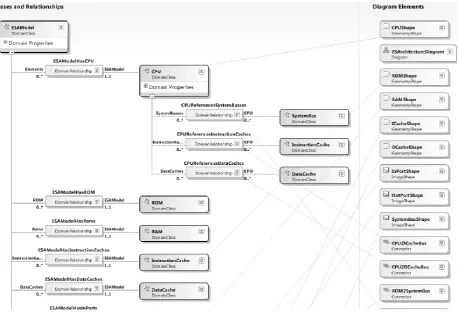
links between domain classes and the shape classes. This XML file is the meta-model file that is built by us and is packaged to design the architectural model of embedded system. Using Visual Studio.NET 2010, we build the meta-model as Fig. 2
TABLE I: THE MAIN CLASSES OF DSL
Logical Classes Shape Classes
ESArchitectureModel ESArchitectureModelDiagram
CPU ComponentShape
RAM RAMShape
ROM ROMShape
Cache CacheShape
BusLocalCPU_Cache BusLocalCPU_CacheShape BusLocalMem_Cache BusLocalMem_CacheShape InPort InPortShape
OutPort OutPortShape BusSystem BusSystemShape Comment CommentShape
After building the meta-model of the DSL, we package this framework as the tool which is used to design architectural model of embedded system. There are many configurations corresponding to the architecture model. From the model, we use T4 to automatically generate parameters. Generated parameters are used as bound of the configuration space of embedded systems. The configuration space specification and optimization problem will be presented in the next section.
IV. MULTI-OBJECTIVE OPTIMIZATION OF EMBEDDED SYSTEM BASED ON PARETO PRINCIPLE AND GA
A. The Configuration Parameters of the Embedded System CPU
ROM RAM
Instruction Cache
InPort OutPort Data Cache
System Bus
Local Bus
Architecture
Definition: the configuration is a set of values corresponding to the parameters describing the components in the system architecture. According to the mentioned architecture in Fig. 1, components of the architecture are parameterized respectively as shown in Table II.
TABLE II: THE COMPONENTS AND RESPECTIVE PARAMETERS
Components Parameters Symbol Unit of measurement
CPU Frequency x1 MHz
RAM/ROM Size x2, x3 MB
Instruction Cache/Data Cache
Size x4, x5 KB
Local bus Address x6 Bit
Data x7 Bit
System bus Data x8 Bit Address x9 Bit
InPort Width x10 Bit
OutPort Width x11 Bit
Configuration vector: based on the parameters describing the architecture in Table I, a configuration of embedded system is characterized by the following vector:
𝑐 = 𝑥1, 𝑥2, … , 𝑥𝑁 (1)
where, x is a parameter in Table II and N is the number of parameters.
Configuration space: is the set of all configuration of the system. Configuration space is the space search or decision space. Configuration space is denoted by C as in formulism (2):
𝐶 = 𝑐1, 𝑐2, … , 𝑐𝑀 (2)
where, c is a configuration and M is the number of configurations.
Each configuration in the configuration space will obtain the different values of performance, power consumption, size, costs. In the configuration space, apply the algorithm to find to the Pareto optimal domain which contains the trade-off configurations between optimal objectives [10].
B. Construct the Objective Functions
Pareto optimal method does not to optimize the special aspect of the system. It aims to balance between optimal objectives. Key of the multi-object Pareto optimal problem is the searching Pareto optimal domain from the search space. Therefore, the best configuration for embedded system under Pareto optimal configuration is the best balance between optimal objectives. The aspects of optimization will be formulated, and evaluated through the objective functions. The optimal aspects for embedded system usually include: performance, power consumption optimization, optimal cost, optimal size, optimal memory, etc. This paper only focuses on analysis, evaluation and construction of the objective functions such as power, performance, area and cost.
The execution speed of the system depends on some factors. It is proportional to CPU speed, the data cache size, the instruction cache size, the local bus width, the system bus width and the memory size. Dependence of the average execution speed on parameters is different so we take the weight array that represents the dependence of the execution speed on these parameters. Moreover, the parameters have
different measure units so they should be converted to the same unit [11]. Here, the parameters are divided by the maximum value of each parameter to eliminate the unit. Finally, the performance objective function is defined as follows:
𝑓𝑝= 𝑤𝑝𝑖 × 𝑚𝑎𝑥 (𝑥𝑥𝑖 𝑖) 𝑁
𝑖=1
and 𝑤𝑝𝑖 = 1 𝑁
𝑖=1
(3)
where:
N: the number of parameters xi: parameter i in Table I max(xi): maximal value of xi
wp: weight array describes dependence of fp on parameters. 0 <= wpi <= 1. When wpi = 0, meaning performance does not depend on xi
2) Power objective function: fe
The power consumption of the system is calculated by the total power consumed by the CPU P1, cache P2, memory P3, Bus P4, I/O port P5. In this paper, we evaluate the power consumption of a second to compare levels of power consumption between the configurations. The general formula to determine the power consumption P as follows:
𝑃 = 𝑃𝑖
5
𝑖=1
(4)
where:
P1 = V × I × f with V is voltage, I is the average amperage and f is frequency. V and I are not almost variant so P1 is proportional to frequency f
P2: the power consumed by the cache is proportional to the size of cache
P3 = V × V × the capacitance of a memory cell × size of memory. V does not change and configurations will be performed the same program to test so P3 is proportional to size of the memory. Memory of embedded system includes both RAM and ROM P4 = V × V × the capacitance of the line × the data
transmission frequency on Bus. With the same program, the number of data transmission times on Bus is alike so the bus power consumption is proportional to the Bus width
P5: the power consumption for the I/O port is proportional to the number of ports and port width Therefore, the power consumption function is built as follows:
𝑓𝑒= 𝑤𝑒𝑖 × 𝑚𝑎𝑥 (𝑥𝑥𝑖 𝑖) 𝑁
𝑖=1
(5)
where, we is the weight array describes dependence of fe on parameters
3) Area objective function: fa
Size of embedded system depends on the key parameters such as Bus width, Bus length, the junctions, number of ports and number of legs. The formula of the area objective functions is as follows:
𝑓𝑎 = 𝑤𝑎𝑖 ×
𝑥𝑖 𝑚𝑎𝑥 (𝑥𝑖) 𝑁
𝑖=1
Cost objective function: fc
Regardless of the development costs, cost per embedded system depends on the components that make embedded system. The cost for each parameter is calculated as cost per unit respectively. The costs for the parameters xi are calculated:
cost(xi) = xi× price of a measure unit
Price per a measure unit of the parameters xi is stored in the array wc. Therefore, the formula for the cost objective function is built as follows:
𝑓𝑐= 𝑤𝑐𝑖 ×
𝑐𝑜𝑠𝑡(𝑥𝑖) 𝑚𝑎𝑥 (𝑐𝑜𝑠𝑡(𝑥𝑖)) 𝑁
𝑖=1
(7)
Global objective function: f
The Pareto optimal domain in the configuration space is selected by maximal value of the objective function. The objective function is built based on the member function. However, the objective function depends on the importance of the member functions. Therefore, we need to build the corresponding weight array that specifies the importance of the member objective functions. The objective function is built as follows:
𝑓 = 𝑤1× 𝑓𝑝+ 𝑤2×
1
𝑓𝑒+ 𝑤3×
1 𝑓𝑎
+ 𝑤4×
1 𝑓𝑐
and 𝑤𝑖= 1 4
𝑖=1
(8)
In the formula, the member function has eliminated measure units so they are able to plus together. Moreover, the Pareto multi-objective optimal problem may be put on the single-objective problem by assigning a weight by one and the remaining weights are zero.
C. Apply Genetic Algorithm to Find Pareto Optimal Configuration
1) Data structure
To find Pareto optimal domain in the configuration space and choose the best configuration of Pareto optimal domain, we use Genetic Algorithm (GA). GA based on genetic theory in fact. In the generation, a couple of genes execute the crossover operator or a gene executes a mutation to create new genes. The good genes are maintained base on the value of adaptive function. After many generations, the best gene will be created [11], [12]. We use GA to search in configuration space because GA is executed parallel so it improves the speed and it is fast convergence.
To apply GA for Pareto optimization, we must define a gene structure. A configuration vector is described as a gene in which each parameter is considered as a chromosome.
Configuration space is the entire population of the colony. In the generation, the genes execute the crossover and mutation to generate new gene. Based on the value of adaptive function, the bad genes are removed.
2) Crossover operator
Crossover is the operator performed between two genes in which gene will swap for the chromosomes to form two new genes. In this problem, two configuration parameters will be exchanged to form two new configurations. Exchange towards possible transfer parameters in a configuration, the remaining parameters were transferred to a second configuration.
3) Mutation operator
Mutation is the operator performed on a gene in which the chromosomes of the gene automatically change the value to generate a new gene.
4) Adaptive function
In GA, the adaptive function is used to select the better genes in each generation. It is built base on the global objective function in the formula (8).
V. EXPERIMENT
A. Design Architecture of Embedded System
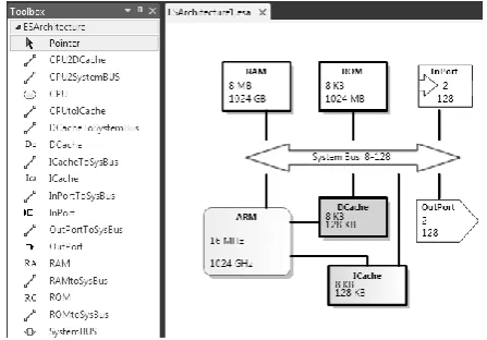
In the section III, we have defined a DSL, built meta-model and created a tool which is used to design architecture model of embedded system. Using our tool, designer can design the architecture of embedded system and can input information of components to optimize. This information including type of component, minimal value and maximal value is used to do Pareto optimization and choose the best configuration. Fig. 3 shows graphical interface of our tool and the architectural model which is designed by this tool.
Fig. 3. Tool and architecture of embedded system.
B. Getting Embedded System Configuration Space from the Architectural Model
To automatically calculate parameters from architectural model, we built T4 template and integrated it to this DSL framework. Fig. 4 shows the information that is automatically generated from model. Parameters are calculated based on this information.
C. Choosing the Optimal Configuration of Embedded System
Fig. 4. Information generated from model.
Fig. 5. Set the parameters and weights.
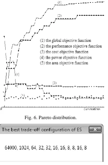
After setting the configuration parameters and weights, installing structural gene, adaptive function is implemented by the formula (8). In the generation we use the crossover 85 percent and the mutation 15 percent. Pareto distribution of the configurations is shown in Fig. 6 and the best trade-off configuration is shown in Fig. 7.
Fig. 6. Pareto distribution.
Fig. 7. The best trade-off configuration.
VI. CONCLUSION AND FUTURE WORK
In summary, the paper has defined a DSL and developed the tool to model architecture of embedded system. The paper has also proposed a method of system-level embedded system optimization based on Pareto principle. In the theory contributions, we have specified and built formalisms of the parameterized embedded system configuration, constructed the objective functions for multi-objective optimization and defined a DSL. Based on the parameters and the objective functions, we also built gene structure, operators and the adaptive function to apply Genetic Algorithms to optimize Pareto. Contributions to the experiment, we have developed DSL tool which is used to design architectural model and automatically generate parameters from model. We have also implemented a program that allows you to choose the best trade-off configuration based on the Genetic Algorithm. Our program is built as library type and optioned parameters to continue to improve the objective functions based on more detail evaluation techniques.
Based on this research, will analyze, evaluate performance and power consumption to apply the Pareto optimization and Genetic Algorithms in optimizing embedded software. And we will also define DSL and develop tool to design the different kinds of model of embedded system.
ACKNOWLEDGMENTS
This research is partly supported NAFOSTED and also by a VNU scientific project (group A) for 2012-2013.
REFERENCES
[1] H.-C. Chiang, “SoC architecture design approaches,” WITS LAB.NSYSU, pp. 5-50, 2004.
[2] H.-C. Chiang, “Introduction to system ic and design flow,” Institute of Communications Engineering, National Sun Yat-sen University, WITS LAB.NSYSU, pp. 3-38, 2003.
[3] Y. Vanderperren and W. Dehaene, “SysML and systems engineering applied to UML-based SOC design,” In Proc. 2nd UML-SOC Workshop at 42nd DAC, Anaheim (CA), USA, pp. 1-13, 2005. [4] OMG, “UML profile for system on a chip,” OMG Available
Specification, version 1.0.1 formal /06-08-01, pp.5-15, August 2006. [5] M. Berekovic “Multicore system-on-chip architecture for MPEG-4
streaming video,” IEEE, pp. 1-10, AUGUST 2002.
[6] T. Givargis, F. Vahid, and J. Henkel, “System-level exploration for pareto-optimal configurations in parameterized system-on-a-chip,”
IEEE, VOL. 10, pp. 416-422, AUGUST 2002.
[7] K. Hammond, “A domain-specific language for real-time embedded systems,” GPCE, pp. 37-56, 2003.
[8] J. Agron, “Domain-specific language for HW/SW co-design for FPGAs,” pro of DSL, pp. 262-284, 2009.
[9] P. V. Huong and N. N. Binh, “A pareto optimal configuration at design phase for SoC platform based on the genetic algorithm,” ICDV 2011, pp. 160-166.
[10] R. Kumar, “On-chip memory architecture exploration of embedded system on chip,” A Thesis Submitted for the Degree of Doctor of Philosophy, pp. 43-80, September 2008.
[11] G. Ascia, V. Catania, and M. Palesi, “An Evolutionary approach for pareto-optimal configurations in SOC platforms,” Dipartimento di Ingegneria Informatica e delle Telecomunicazioni, Università di Catania, pp. 1-12, Italy 2005.