IJEDR1504035
International Journal of Engineering Development and Research (www.ijedr.org)1
Color Based Detection and Range Estimation of an
Obstacle Using Two-view Triangulation
1Er Monika 2Rupinder Kaur 1M Tech Scholar 2Assistant Professor
Doaba Institute of Enginnering and Technology,Kharar,Punjab,India.
________________________________________________________________________________________________________ Abstract - Obstacle detection is a major key of autonomous vehicles. When communicating with huge robots in unstructured background, resilient obstacle detection is required. Few of the existing methods are mostly suited for the backgrounds in which the ground is comparatively flat and with roughly the similar color throughout the terrain. A novel procedure future in the work presented here uses a monocular camera, for real-time performance. We compute the homography between two successive frames by computing the fundamental matrix between the two frames. Estimation of fundamental matrix is followed by triangulation so as to calculate the distance of the object from the camera. We examine a difficulty intrinsic to any fundamental matrix-based outlook to the provided task, and explain how the discussed way can resolve this difficulty by a huge level. An obstacle detection and distance estimation system based on visual particular attribute and stereo vision is hence discussed in the presented work.
Keywords - Face recognition, Preprocessing, characteristics match, Image Processing etc.
________________________________________________________________________________________________________
I.INTRODUCTION
With increase in road hazards day by day, technology is necessary to be better with respect to safety measures to avoid obstacle in the path traversed by the vehicle. Obstacle detection is the methodology that refers to the ability to detect the obstacle that appears in that hinders the path of the object. It helps the vehicles; robots etc. to take result so that they avoid collision when there is any obstacle in their path. Generally an obstacle is a situation or object that creates barrier or any impediment which stops or halts the movement of the vehicle. An obstacle can be natural or man-made or it may be that it is combination of together. Earlier methods for obstacle detection faced issues, because hardware uses sensors like Ultrasonic range detector, LiDAR etc. To detect obstacles which are either economically expensive or possess low range. Apart from this, the sensors require high computational power. There are further issues that mainly of the sensors work in line of sight. This reduces the field of view of the sensors. Therefore camera based method can be a probable solution to above issues, as now-a-days all the autonomous vehicles possess camera and hence an extra sensor is not a requirement now. The major objective of this work is to detect the obstacle on the basis of color cue. Any obstacle is detected by its color from the monocular or binocular camera. Position can be calculated by finding the distance which in the computer vision fraternity known as triangulation. The technique of triangulation makes use of the relative orientation of the two frames of similar object so that distance can be detected.
In computer vision, triangulation refers to the process of determining a point in 3D space given its projections onto two image or more images. This point is an interest point of two frames of same image. Triangulation of a set of points in 2D image computes any other operation in the form of sparse matrix on triangulations of order 3. This model normally calculates the position of obstacles according to a monocular camera by using color information. Two frames which capture the colored object are processed in order to obtain the centroid of the imaged object.. This work describes an obstacle detection algorithm for use in for all types of terrain but provided the obstacles are differentiated by color. If the obstacle is in the range then unnamed vehicle or human-being can take decision accordingly so as to avoid collision. Therefore we prefer vision based methods. The advantages of these methods are as follows:
1. Vision based method are comparatively less expensive as compared to others because these system require only camera for obstacle detection whereas other rely on sensors although they have cameras mounted on the vehicle.
2. They are low power consumption because it requires less computation as compare to laser. 3. The technique performs relatively improved in terms accuracy as compared to existing techniques.
Now-a-days, use of automotive vehicle, air vehicle and mechanism system are increasing noticeably. So, thereby a number of problems are also increasing in their path. Accident with an object is one of the main problems and this object is outlined as an obstacle. Obstacle detection could be a way for protection from such obstacles from any kind of autonomous vehicles, human being or any other object.
An object or factor that makes some obstruction is known as obstacle. For various surroundings, obstacles are often outlined in several types, which are as following
IJEDR1504035
International Journal of Engineering Development and Research (www.ijedr.org)241
For visually impaired people obstacle is often known as “something that can stop blind people or change the movement of hiscurrent direction”. In this case obstacle can be anything like glass, door etc. For safety reason blind peoples use white cane however, it is not always very helpful while travelling as it cannot differentiate between color.
For an autonomous navigation vehicle “obstacle is something that can cause some hazard or accident, once it meets with host vehicle”. Therefore, obstacle is something that forestalls or delays some action in any surroundings. In many vehicles there are some buzzers that get activated and make warning, if it detects some obstacle in its path.
II.LITERATURE REVIEW
Iwan Ulrich and Illah Nourbakhsh, in this paper displays vision-based impediment speech act methodology for the compact robots. Every individual image has constituent is called having a spot either to associate degree obstacle or bottom considering its shading look. The framework used a lone unapproachable performs unceasingly, shading camera, and provides a matched hindrance image at large determination. The structure is organized by merely driving mechanism through its environment. Within versatile mode, the structure may keep taking within neck of woods of bottom within the interior of operation. The system has tested with success in a very type of environments, inside further as outdoors .This paper given a replacement method for obstacle detection with one color camera. The strategy performs in the real- time and offers a binary obstacle image at high resolution. The system will be trained and has performed well in very type of environments, inside further as outdoors. [1].
Ashish R. Derhgawen and D. Ghose, in this paper exhibits fast obstruction recognition algorithm for the transportable robots uses a solitary shading camera because major device to the spot obscure snags in a very state of affairs. The estimate can used shading HSV histograms to order an each individual constituent that having an area either to snag, or bottom in the lightweight of its look. The framework is supplied for the playing early impediment discovery on each uniform territories. The robot’s solely goal to date in experiments has to maneuver around safely in the unstructured environments by avoiding obstacles. The remarkable line of work may well be to com- Humulus this method with navigation and path designing algorithms to permit it to maneuver towards targets, or perhaps for exploration and mapping of remote locations. [2].
James Bruce Tucker Balch and Manuela veloso, Vision frameworks utilizing district division by the shading square calculate
pressing an unceasingly transportable mechanism application, an example, Robo Cup, or the complete different areas communication with the hu-keeps watch on or dynamic world has required. Usually, systems utilizing continue shading primarily based division square calculate either the dead in instrumentality, or specific programming frameworks that take benefit of the space data to realize the basic efficiency. However; we've got found that with careful attention to formula efficiency, quick color image segmentation will be accomplished mistreatment goods image capture and mainframe hardware. Our work are describes a system capable of pursuit many hundred regions of up to thirty two colors at thirty Hertz on general purpose goods hardware. [3].
Richard I. Hartley and Peter Sturm there is tendency to contemplate the substance of finding the position of a degree in house
given its position in two pictures gaga cameras with acknowledged standardization and cause. This technique requires intersection of the two acknowledged rays in house and is often called triangulation. All strategies are performed comparatively for the geometrician re-construction, as calculated in the terms of 3D error. Within the case of 2Derror, only the methods Poly–Abs iterative–LS, Polynomial, and Iterative–Eigen perform acceptably, and last two have the disadvantage of occasional non convergence. [4].
Ricardo Neves and Anibal C Matos presents an approach to the stereovision applied to the tiny water vehicles. By using a tiny
cheap pc and cheap off-the-peg elements, a tendency to expand an autonomous driving system which is capable of following distinct vehicle and moves on ways delimited by colored buoys. A try of webcams has been used and, with associate degree ultrasound device, a tendency to implement a basic frontal obstacle shunning system. With assistance of stereoscopic system, there has a tendency to position the objects that function references to ASV steerage. The final system has capable of distinguishing and following targets in very distance of over five meters. The system is ready to accomplish operate it’s designed for below USD seventy. In this work, it’s been tested that it there's likelihood of playing stereoscopic image process mistreatment low price procedure units. Results of 2-3 FPS were tested come-at-able. Though mistreatment a lot of dense similar algorithms continues to difficult task to those tiny units, mistreatment less complicated techniques involving binary imaging and criterions chosen 3D information could be a great way of surpassing those limitations. [5].
Peter Lindstrom, have a tendency to describe a simple and efficient formula for two- read triangulation of the 3D points from
IJEDR1504035
International Journal of Engineering Development and Research (www.ijedr.org)242
III.PROBLEM FORMULATION
The existing techniques assume that the obstacles contrast in appearance from the ground. The ground is assumed to be relatively flat. Also, there are no overhanging objects. The first assumption distinguishes obstacles from the ground, while the other two assumptions calculate the distances between obstacles and the camera. If the ground is flat and there are no overhanging obstacles, then the distance is a monotonically increasing function of the pixel height in the image. If the ground is not flat or if there are overhanging obstacles, then the distance calculate would be erroneous. Hence a system is required to calculate the distance non-erroneously.
IV. METHODOLOGY
The algorithm uses the area immediately in front of the as a reference region and computes its RGB channels. The histogram of this area is compared to other parts of the image to find objects that are likely to be obstacles. The depth of this reference region can be manually adjusted depending on the terrain. A deep reference region will provide more information, but it could also contain obstacles. The reference region is manually adjusted to be deep enough to provide sufficient information of the terrain without including any obstacles.
The RGB data of this area is then back projected onto the rest of the image to detect the presence of obstacles. The result of back projection is a single channel probability image that shows the pixels that are most likely to be an obstacle. This probability image is then threshold to obtain a binary obstacle image. By adjusting the probability threshold, it is possible to make the system work on multicolored surfaces. The main steps of the algorithm are:
1) Perform noise removal on input image 2) Estimate RGB channels of reference region 3) Back projection
4) Find pixels that are most likely to be part of an obstacle 5) Find connected components (blobs) in the image
In the first step, a mean filter is applied to the color input image. This reduces the noise from the image. This has the effect of removing pixel values which are unrepresentative of their surroundings. Second step, a rectangular region immediately in front of the robot is used as a reference region, and its HSV histogram is estimate. If the value of a pixel is below this critical value, it is classified as black. Similarly, hue is estimate only if the saturation of a pixel is above the saturation threshold value (which is approximately 20% of maximum saturation). If the value is below the saturation threshold, it is termed as white. If both brightness and saturation values are above their respective threshold values, only then the hue of the pixel is calculated. It is not important in our case to represent every shade of luminance and saturation as these two parameters are only used to differentiate between colorful pixels (pixels with valid hue values), and dark/white pixels. Histograms consume little memory, and can be estimate very quickly. This makes them well suited for this application.
Facilities required and Proposed Methodology
The facilities required for the proposed work are: 1. Set of image frames with the obstacle.
2. The obstacle should be identifiable because of its color 3. Base technique implementation for further improvement The block diagram of proposed technique is shown in fig 1.
Fig: 1
IJEDR1504035
International Journal of Engineering Development and Research (www.ijedr.org)243
2. Image Segmentation method is then used to divide images into parts to correlate between interested objects and rest ofobjects. This operation will be done on the pixels of images based on RGB values.
3. Thresholding is then applied because it helps to differentiate between obstacle and ground. It means for instance we say if value of the Red pixel is 220 and the threshold value is 128. And if the value is greater than threshold then it is obstacle else it is free space. Finally, fundamental matrix estimate is done in order to facilitate the triangulation process. The triangulation process requires the fundamental matrix between the two frames to calculate the distance of the camera from the objects.
4.
Center Detection: It is compulsory to detect the center point of image so that we can apply triangulation
technique to calculate distance. Here we required to detect center of two frames of same image.
5. Fundamental Matrix calculate: Sometimes camera parameter for example focal length occurs some reflection in image if this parameters are known then fundamental matrix does not require else it requires.
6. Triangulation: This is most important because when the two rays projected on the camera then it gives a point where two rays of frames are intersected. So distance can be calculated from any one of the frame to camera.
Triangulation
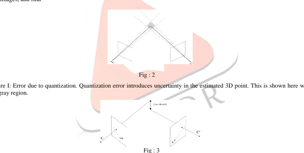
The motion estimation from 3D correspondences and from 3D and 2D features correspondences requires image points to be transformed back into 3D point. Over the last few decades, development of computer vision methods for estimating the position of a point in space, has been the goal of many research programs for the applications ranging from guidance and control to 3D structure reconstruction. This process of calculate the location of a point in space, using its projection in two views, is known as triangulation. The basic method of triangulation is by the back-projecting rays corresponding to the 2D image points, from the two images, and find
Fig : 2
Figure I: Error due to quantization.Quantization error introduces uncertainty in the estimated 3D point. This is shown here with the gray region.
Fig : 3
Figure 3:Triangulation error. Due to error, the measured points may deviate from the epipolar line.
This is popularly known as Direct Linear Transform, which minimises the algebraic distance. However, due to the noise in the estimated 2D image points, which involves quantization noise, geometric error and characteristic matching uncertainty, the triangulation problem has become non-trivial. The quantization noise results in the uncertainty in the position of the point because of which the 3D point can lie in the shaded region.
In order to obtain a improved estimate of the position point in space, several methods have been proposed in the past. The midpoint technique, proposed by Beardsley et al., computes the midpoint of the shortest distance between the two rays. Although few improvements have been incorporated to this method, they do not provide an optimal output owing to various approximations. An optimal technique to minimize the error is by considering the re-projection error as the cost function
non-IJEDR1504035
International Journal of Engineering Development and Research (www.ijedr.org)244
linear optimization methods are used to obtain an optimum solution, but methods like evolutionary algorithms have also found their place. Vite-Silva et al. have used multi-objective evolutionary algorithm whereas Wong and Ng implemented Particle Swarm Optimization for finding the optima, but these algorithms are computationally expensive and hence can be used if there are only few noisy corresponding points.A landmark work in this field was that of Hartley and Sturm, who reformulated the cost function by considering the Euclidean distance between the image point and corresponding epipolar line. Henceforth the technique will be referred to as polynomial. The focus of the technique is that the dimensionality of the cost function has been reduced to only one variable, with the solution meeting the epipolar constraint. Hence finding the optima became easier, thereby finding an optimal solution to the problem. VI. RESULTS
The depth calculation algorithmic formula included a measurement error which is termed as epipolar error given by
x’T F x = 0;
It is an empirical model for error function where x’ is the corresponding image point in the second image, F is the fundamental matrix and x in the image point in 1st image. In the base paper defined, they have used the disparity method to estimate the depth. Hence, epipolar error is one of the important aspects to find whether the estimated value is totally correct or not.
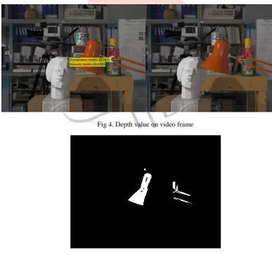
When depth values are estimated by calculating for error using error function, it has been found that the epipolar error is very large.
The changed error varies with actual depth as well as the frames are coming. The effect of this error over depth measurement results in slight variations in the location of corner points. The error in localization results in inclinations of the edges that are straight with the actual object. Though it can be observed from the image frames that as the frames are coming the camera is moving closer to the obstacle, the epipolar error is increasing largely.
Fig 4. Depth value on video frame
IJEDR1504035
International Journal of Engineering Development and Research (www.ijedr.org)245
Fig. 6 Epipolar error and Depth error compared for both methods.
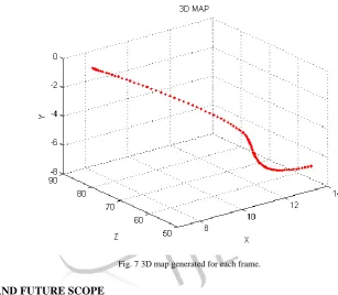
Fig. 7 3D map generated for each frame.
V. CONCLUSION AND FUTURE SCOPE
In this thesis various methods for detection of objects on the basis of color are discussed. Different algorithms like niter is discussed which minimize the epipolar error. A hybrid method based on color cue and triangulation method is future work. In Color based obstacle detection, obstacle detect based on color cue. Pixels in any image can be classified on the basis of like R, G, and B. In triangulation technique when the two rays projected on the camera then it gives a point where two rays of frames are intersected. So distance can be estimate from any one of the frame to camera.
The advantage of the future method is to estimate the distance with minimum epipolar error as compared to disparity based technique. The limitation of the technique is that the error keeps on increasing as we move on to the consecutive frames. This kind of error is termed as drift error. Therefore, the future work may rely upon the minimization of the drift error also so as to get the correct calculate for each pair of frames.
REFERENCES
[1] R.C. Luo, T.Y. Lin, T.Y. Hsu, and P.K. Wang, Multisensor controlled obstacle avoidance and navigation of intelligent security robot, 31st IEEE Annual Conference of Industrial Electronics Society, Raleigh, NC, USA, pp. 1827-1832, 2005.
IJEDR1504035
International Journal of Engineering Development and Research (www.ijedr.org)246
[3] Webb, E. J., Campbell, D. T., Schwartz, R. D., & Sechrest, L.Unobtrusive measures: Nonreactive measures in the social sciences. Chicago: Rand McNally.[4] R. I. Hartley. Estimation of relative camera positions for uncalibrated cameras. In Computer Vision - ECCV ’92, LNCS-Series Vol. 588, Springer-Verlag, pages 579 –587, 1992.
[5] R. I. Hartley. Lines and points in three views - a unified approach. In Proc. ARPA Image Understanding Workshop, pages 1009–1016, 1994.
[6] Richard I. Hartley. Euclidean reconstruction from uncalibrated views. In Applications of Invariance in Computer Vision : Proc. of the Second Joint European – US Workshop, Ponta Delgada, Azores – LNCS-Series Vol. 825, Springer Verlag, pages 237–256, October 1993.
[7] Jan J. Koenderink and Andrea J. van Doorn. Affine structure from motion. Journal of the Optical Society of America, A, 1992.
[8] H.C. Longuet-Higgins. A computer algorithm for reconstructing a scene from two projections. Nature, 293:133–135, Sept 1981.2005
[9] R. Mohr, F. Veillon, and L. Quan. Relative 3D reconstruction using multiple uncalibrated images. In Proc. IEEE Conf. on Computer Vision and Pattern Recognition, pages 543 – 548, 1993.
[10] Jean Ponce, David H. Marimont, and Todd A. Cass. Analytical methods for uncalibrated stereo and motion reconstruction. I n Computer Vision - ECCV ’94, Volume I, LNCS-Series Vol. 800, Springer-Verlag, pages 463–470, 1994.
[11] William H. Press, Brian P. Flannery, Saul A. Teukolsky, and William T. Vetterling. Numerical Recipes in C: The Art of Scientific Computing. Cambridge UniversityPress, 1988.In Proc. KDD 2000 Workshop on Text Mining, Boston, MA.
[12] Sahami, M., Dumais, S., Heckerman, D., & Horvitz, E. (1998, July). A Bayesian approach to filtering junk e-mail. In Learning for Text Categorization: Papers from the 1998 workshop (Vol. 62, pp. 98-105).