R E S E A R C H
Open Access
Joint coding in parallel symmetric
interference channels with deterministic
model
Yifan Xue, Yafei Tian
*and Chenyang Yang
Abstract
In parallel interference channels, the sum-rate achieved by joint coding among subchannels can exceed the sum of the achievable rate of each subchannel with individual coding. In this paper, a capacity-achieving joint coding scheme is proposed for parallel symmetric interference channel. First, we provide a motivating example, from which the insights into the joint coding scheme are obtained. Second, we introduce a transmission scheme in two-user parallel symmetric interference channels, where the subchannels can cooperate to cancel interference. Then, by taking advantage of signal level alignment of the interference from different users, we generalize the scheme to multi-user cases. Finally, we prove that our scheme can achieve the sum capacity and illustrate the generalized degrees of freedom gains over individual coding in various interference scenarios.
Keywords: Deterministic model, Generalized degrees of freedom, Interference alignment, Joint coding, Parallel interference channel
1 Introduction
Parallel interference channel is a collection of subchan-nels where each subchannel is an interference channel but there is no interference between the subchannels. The typical parallel interference channels are frequency-selective orthogonal multicarrier interference channel and time-varying multi-symbol interference channel.
When considering parallel interference channel, many researchers focused their attentions on separate coding over each subchannel [1–3]. This might be due to the well-known fact that parallel point-to-point channel, multiple-access channel and broadcast channel are all separable. However, parallel interference channel is not separable in general. As shown by a counterexample in [4], joint coding across multiple subchannels outperforms individually optimal coding. Recently, for the two-user parallel Gaussian interference channels, Shang et al. [5] determined the conditions on the channel coefficients and power constraints under which independent coding across subchannels (i.e., treating interference as noise) is optimal. ForK-user parallel deterministic interference
*Correspondence: [email protected]
School of Electronics and Information Engineering, Beihang University, 37 Xueyuan Road, Haidian District, Beijing 100191, China
networks, Sun and Jafar [6] derived the conditions under which treating interference as noise at each subchannel is optimal. For two-user ergodic Gaussian interference channels, Sankar et al. [7] showed that under certain con-ditions, joint coding across the fading states, which can be seen as subchannels, is required for optimality.
In this paper, the link between a transmitter and its desired receiver is denoted as direct-link, and the link between a transmitter and its undesired receiver is denoted as cross-link. For individual coding in each sub-channel, the existence of cross-link can only deteriorate the direct-link transmission [8–10]. In weak interference channels, the interference will decrease the signal-to-interference-plus-noise ratio (SINR). In strong interfer-ence channels, although the interferinterfer-ence can be decoded and then canceled, it occupies higher signal ampli-tude levels, leading to a reduced transmission rate of desired signals.
Recently, research results change this pessimistic point of view and reveal that the interference can actually be exploited to help decoding. In [11], the linear interfer-ence network problem is translated to the index coding problem. The authors used an example to show that the interference bit decoded in the second time slot can be used to cancel the interference encountered in the first
time slot. In [12, 13], the interference signal goes through two cross-links through feedback and finally becomes desired signal.
In parallel interference channels, the strong interfer-ence subchannels can be used to help the decoding of other weak interference subchannels by retransmitting the bits that generate interference, as will be explained in the subsequent sections. However, when two users retrans-mit their information simultaneously in the same strong interference subchannel, they also interfere with each other. In [14], this problem was simplified by only using individual coding on strong interference subchannels. In [15], considering a specific scenario, only one user was allowed to transmit on these strong interference subchan-nels. In [16], a capacity-achieving joint coding scheme was proposed for two-user two-subchannel symmetric deter-ministic interference channel, but the proof of capacity achieving is divided into multiple subcases, and the corre-sponding joint coding schemes are respectively designed for each subcase. Due to the lack of systematic design principle, this scheme is hard to be generalized to par-allel interference channel with multiple subchannels and multiple users. In [17], the parallel symmetric two-user interference channels were studied when the interference is bursty and feedback is available from the receivers. With the help of channel bursty and feedback, the sub-channel in very strong interference regime can help to recover the signals for subchannels in strong and weak interference regime. However, the scheme does not work in constant interference channels, and there is no mech-anism to let the strong interference subchannel help the weak interference subchannel.
In this paper, we study joint coding problem over par-allel symmetric interference channel with multiple sub-channels, where each subchannel is constant over the coding block and no feedback information from the receiver is available. First, we introduce a transmission scheme under two-user parallel symmetric determinis-tic interference channels. Then, we extend the scheme to multi-user cases using the principle of signal level align-ment. To prove the optimality of this scheme, we derive the capacity of this class of channels by using El Gamal and Costa’s result [18] and show that the proposed scheme can achieve the sum capacity. Finally, we illustrate the gener-alized degrees of freedom (GDoF) gains of the proposed joint coding scheme over the individual coding scheme in various interference scenarios.
The capacity or GDoF analyses of the interference chan-nel through the help of deterministic chanchan-nel model have been got a lot of attentions in recent years, but few of them studied the parallel interference channel. For exam-ple, in [19], the sum capacity of a special case ofK-user Gaussian interference network is determined withinO(K) bits, where only one of the users interferes with and is
also interfered by all the other users. Multi-user cognitive interference network is studied in [20], where secondary users have a priori non-causal message knowledge of pri-mary license holders and can transmit signals to neutralize the interference appeared in primary receivers. Symmet-ric interference relay channel is studied in [21], where a full-duplex relay is present to coordinate the interfer-ence. Furthermore, multicoding scheme is developed in [22], by which the same rate region compared with Han-Kobayashi coding is achieved in two-user discrete mem-oryless interference channel. In [23], a tight converse for two-user deterministic interference channel is derived by extended network and generalized cut-set bound.
The rest of this paper is organized as follows. In Section 2, we provide the deterministic model for K -user parallel symmetric interference channels. Then, in Section 3, we introduce the individual coding scheme and its achieved GDoF for symmetric interference chan-nels. In Section 4, the joint coding schemes are developed in two-user and multi-user cases, respectively. We prove the optimality of the proposed joint coding scheme in Section 5, where the GDoF gains over individual cod-ing are illustrated through analysis and numerical results. Finally, Section 6 concludes this paper.
2 Channel model
It is hard to study the parallel interference network prob-lem under Gaussian channels. In this paper, we resort to the deterministic channel model proposed in [24], which approximates the Gaussian channel as a discrete set of parallel noiseless channels [24, 25].
For the convenience of readers, we first introduce the deterministic model of point-to-point channel proposed in [24] and define several notions to be used subsequently. Then, we introduce the deterministic model of inter-ference channel, in which each link is modeled in the same way as in point-to-point channel. Finally, we provide the deterministic model of parallel symmetric interfer-ence channel, in which each subchannel is modeled as in interference channel.
2.1 Deterministic model of point-to-point channel In point-to-point Gaussian channel, a real-valued input xgenerates a real-valued outputydegraded by Gaussian noisez, i.e.,
y=hx+z, (1)
where his the channel coefficient, E[|x|2]= P, and the variance of z is N0. The signal-to-noise ratio (SNR) is defined as |h|2P/N0 = γ. If the powers ofx andz are normalized to 1, then the effective channel gain is√γ.
notation as
¯
x=0.b1b2b3b4b5. . ., (2)
where each bit bi ∈ {0, 1}, which can be interpreted
as occupying a signal level, and the most significant bit corresponds to the highest signal level.
Definition 1(signal level)In a deterministic channel, we quantize signal into multiple layers. Each layer is referred to a signal level, or simply called a level.
Definition 2(bit) Each part of the signal in one level is called a bit. Obviously, all the bits compose the signal.
Definition 3(relative level order)Different bits from a signal occupy different levels. Relative level order of two bits refers to the relative height between the two levels that they occupy. There are three kinds of relative level order between a pair of bits: higher, lower, and equal.
Given the SNRγ, the output of the deterministic chan-nel is
¯
y= 2Mx¯ =b1b2. . .bM, (3)
whereM = 12log2γis the largest integer below log2γ andbMis the lowest signal level above the noise. In other
words, the input bit sequence is shifted by Mpositions and the remaining part afterbM is truncated due to the
degradation of noise.
Since there is no interference, the receiver can obtainM bits. The capacity of deterministic point-to-point channel is defined as
CP2P(SNR)= 1
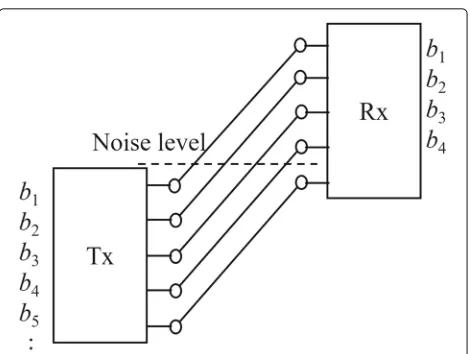
2log2γ =M. (4) The shifting and truncation operations are illustrated in Fig. 1. In Fig. 1,b1,b2. . .are bits occupying different levels. For example, the relative order betweenb2andb5 is thatb2 is higher thanb5. Besides, the capacity of this channel isCP2P(SNR)=4.
2.2 Deterministic model of interference channel
InK-user Gaussian interference channels, the inputs ofK users form a vectorx, and the output vector is
y=Hx+z, (5)
where the entry of channel matrixHi,jstands for the
chan-nel gain from transmitter j to receiver i. The noise of different users is assumed to be independent and iden-tically distributed (i.i.d.), and E[zzH]= N0I. The SNRs depend on the channel gains of the direct-link, which areγk,k = |Hk,k|2Pk/N0. The interference-to-noise ratios (INRs) depend on the channel gains of the cross-link, which areγi,j= |Hi,j|2Pj/N0,i=j.
Fig. 1Deterministic model of a point-to-point channel
For a K-user deterministic interference channel, the channel inputs can be written in a base-2 notation, i.e.,
¯
x1 = 0.a1a2a3a4a5. . .,
¯
x2 = 0.b1b2b3b4b5. . ., ..
.
¯
xK = 0.k1k2k3k4k5. . .,
(6)
whereai,bi,· · ·,ki∈ {0, 1}.
At the receiver, the outputs of the direct-link channel and cross-link channels are added together. Specially, the signal addition takes the form of XOR, i.e., modulo-2 addi-tion. Therefore, the addition of signal and interference on one signal level does not affect that on other signal lev-els. The bits that are lower than noise level are lost in this model. This simplification allows us to more focus on the interactions between signal and interference.
Define Mi,j = 12log2γi,j and apply (3) to every
direct-link and cross-link of (5). Then, the output can be written as
¯
y1 = 2M1,1x¯1 ⊕ 2M1,2x¯2 ⊕ · · · ⊕ 2M1,Kx¯K,
¯
y2 = 2M2,1x¯1 ⊕ 2M2,2x¯2 ⊕ · · · ⊕ 2M2,Kx¯K,
.. .
¯
yK = 2MK,1x¯1 ⊕ 2MK,2x¯2 ⊕ · · · ⊕ 2MK,Kx¯K.
(7)
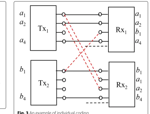
An example of the two-user deterministic interference channel is shown in Fig. 2, where we denote the direct-link as solid lines and denote the cross-link as dotted lines.
2.3 Parallel symmetric interference channel
In a two-user symmetric interference channel, the SNRs of two direct-link channels are identical and the INRs of two cross-link channels are identical, i.e.,γ1,1=γ2,2andγ1,2=
Fig. 2A two-user deterministic interference channel
are the same as well. In this kind of channel, each user generates interference to other users at the same levels.
In a symmetric interference channel, if the INR is larger than the SNR, we call it a strong interference channel. Otherwise, we call it a weak interference channel. Specif-ically, in deterministic channels, the strength of inter-ference is expressed by the number of levels. Thus, if there are less cross-link levels than direct-link levels in a deterministic symmetric interference channel, it is a weak interference channel. Otherwise, it is a strong interference channel. For a network with more than one symmetric interference subchannels, we call it a parallel symmet-ric interference channel, where each subchannel may be a strong or weak interference channel. The difference among subchannels comes from frequency-selective or time-selective fading, i.e., each subchannel may experi-ence different channel fading. An example of a two-user three-subchannel parallel symmetric interference channel is shown in Fig. 5.
In Fig. 5, there is only one transmitter and one receiver for each user. For example, the Tx1 blocks in different subchannels belong to the same transmitter of user 1.
3 Individual coding
Most of previous researches on interference channels focus on individual coding, which means that the cod-ing scheme is taken in each subchannel individually, and there is no cooperation among multiple subchannels. In this section, we will first give an example of the opti-mal individual coding scheme in a two-user deterministic interference channel and then present the known GDoF results forK-user symmetric interference channels.
3.1 An example of individual coding
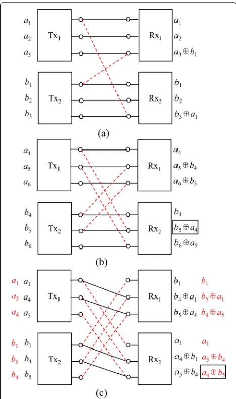
Figure 3 is an example of the individual coding in a two-user deterministic interference channel where the interference conditions are the same as in Fig. 2. It can
Fig. 3An example of individual coding
been seen that because of the mutual interference, some signal levels must be muted; otherwise, the superposition bits are not decodable and the system throughput will be degraded. As shown in Fig. 2, if all the signal levels are occupied, only three bits can be decoded for the two users. However, if using the transmission scheme shown in Fig. 3, i.e., user 1 transmits on levelsa1,a2, anda4and user 2 transmits on levelsb1andb4, totally five bits can be decoded. Through exhaustive searching, we can find that the sum capacity of this channel is exactly 5, and the pre-sented scheme in Fig. 3 is thus the best individual coding scheme for this channel.
3.2 Generalized degrees of freedom
For the general K-user symmetric interference chan-nels, an individual coding scheme is presented in [10]. Although the scheme is originally designed for Gaussian interference channels, the deterministic model is used in the derivations, and it thus can be easily applied in deter-ministic interference channels. In [10], the GDoF of the K-user symmetric Gaussian interference channel is also derived.
The GDoF per user is defined as
d(α)= 1
K SNRlim→∞sup
C(SNR,α) CP2P(SNR)
, (8)
whereCP2P(SNR)is the interference-free capacity for one user,C(SNR,α)is the sum capacity of theK-user inter-ference channel, and
α= log INR
log SNR (9)
GDoF denotes the ratio of the average sum capacity of the interference channel normalized by the capacity of the point-to-point interference-free channel when the SNR approaches infinity. ForK-user symmetric Gaussian interference channels,
CP2P(SNR)= 1
2log(1+SNR), (10)
and the GDoF is characterized as the following piecewise function [10],
d(α)= ⎧ ⎪ ⎪ ⎪ ⎪ ⎪ ⎪ ⎨ ⎪ ⎪ ⎪ ⎪ ⎪ ⎪ ⎩
1−α, α∈(0,12)(noisy weak)
α, α∈(12,23)(fairly weak) 1− 12α, α∈(23, 1)(moderately weak)
1
K, α=1
1
2α, α∈(1, 2)(moderately strong) 1, α∈(2,+∞)(very strong)
.
(11)
In this function, the weak interference scenario is fur-ther subdivided into three cases and the strong inter-ference scenario is further subdivided into two cases, according to the value ofα. The piecewise GDoF curve is shown in Fig. 4, where the GDoF achieves maximum in interference-free scenario or very strong interference scenario.
ForK-user symmetric deterministic interference chan-nels, the GDoF function is as same as in (11), since the difference of the sum capacity in deterministic interfer-ence channel and in Gaussian interferinterfer-ence channel is within finite bits [10]. When the SNR approaches infinity, the ratiod(α)will go to the same.
Fig. 4GDoF ofK-user symmetric Gaussian interference channel
4 Joint coding scheme
In parallel interference channel, the signals in different subchannels of one user is transmitted by the same trans-mitter; thus, the subchannels can be jointly encoded. Similarly, the signals received in different subchannels of the same user can be jointly decoded. The basic idea of the proposed transmission scheme is as follows. In weak interference subchannels, the bits is transmitted at the maximal possible data rate of the direct-link with-out considering the existence of cross-link interference. In strong interference subchannels, the bits that will generate interference in weak interference subchannels is retrans-mitted following a certain rule. The received signals in weak interference subchannels and strong interference subchannels are then jointly decoded.
4.1 A motivating example
To show the basic idea of our joint coding scheme, we first see a simple example. As shown in Fig. 5, the two-user parallel interference channel has three subchannels, we call them subchannels I, II, and III. The number of levels in the direct-link is three in both subchannels I and II. The number of levels in the cross-link is one and two in subchannel I and II, respectively. In sub-channel III, two signal levels exist in the direct-link and three signal levels exist in the cross-link. According to the statements in Section 2.3, subchannels I and II are weak interference channels, while subchannel III is a strong interference channel.
In subchannel I, user 1 and user 2 transmit their bits on all signal levels of direct-link regardless of interference. Specifically, Tx1transmitsa1, a2, anda3and Tx2 trans-mitsb1,b2, andb3. Obviously, there are interference at the two receivers as can be seen from Fig. 5a. In particular, since the number of direct-link signal levelsM1,1=3 and that of cross-link signal levelsM2,1 = 1, a bita1⊕b3is received at Rx2, which means thatb3is interfered bya1. Because the channel is symmetric for two users, the inter-ference scenario is similar at Rx1, i.e.,a3is interfered byb1. Provided the received bits in subchannel I, onlya1anda2 are decodable at Rx1and onlyb1andb2are decodable at Rx2. The contaminated bitsa3andb3cannot be decoded without external help.
Subchannel II is also a weak interference channel, we use similar transmission strategy as in subchannel I. The num-ber of cross-link signal levels of this subchannel is larger, M1,2 = M2,1 = 2. Therefore, although three bits are still transmitted for each user, two bits are interfered at each receiver, and onlya4andb4can be decoded.
Fig. 5A two-user parallel interference channel with three subchannels.aSubchannel I.bSubchannel II.cSubchannel III
Subchannel III is a strong interference channel, where three signal levels exist in the cross-link channel. The transmission scheme in this subchannel is critical. It determines whether the contaminated bits in subchannels I and II are decodable, and affects the spectrum utilization efficiency of the parallel interference channel.
The bits that will generate interference in weak inter-ference subchannels are retransmitted in subchannel III, which is used to recover the contaminated bits in sub-channel I and subsub-channel II. To avoid the interference between user 1 and user 2 in retransmission, a straight-forward scheme at hand is orthogonal-based transmission schemes, so that there is no interference between user 1 and user 2. For example, in the first time slot, Tx1 retransmitsa1,a4, anda5. Through the cross-link, these bits arrive at Rx2and can be used to cancel the interfer-ence appeared in subchannels I and II. In the second time
slot, Tx2 retransmits b1,b4, and b5, and Rx1 uses these bits for interference cancelation. However, this scheme is obviously inefficient.
A better choice is to let Tx1 and Tx2 retransmitting simultaneously in subchannel III. As shown in Fig. 5c, both Rx1 and Rx2 obtain contaminated bits and can-not recover these bits individually. However, taking into account the received bits in subchannels I and II, these bits can be jointly decoded. For Rx1, in three subchannels, totally nine bits are obtained, which can be expressed as follows:
r11 =a1, r12 =a2, r13 =a3⊕b1, r14 =a4, r15 =a5⊕b4, r16 =a6⊕b5, r17 =b1, r18 =b4⊕a1, r19 =b5⊕a4,
(12)
where r1i, i = 1,· · ·, 9 is the received bits at Rx1. We can see from (12) that each received bit correspond to an equation and all the received bits provide us with a set of equations.
It can be seen that a1,a2,a4, and b1 can be obtained immediately whenr11,r12,r14, andr17is received. But the other five received bits are not simply transmitted bits from user 1 or user 2, none of which can be recovered by a single equation. Fortunately, the nine equations in (12) are linear uncorrelated, and there are only nine unknown variables in (12). By solving the set of equations, all the nine bits can be recovered. In these bits, six are transmit-ted by user 1, which are the desired bits. The other three bits, which are transmitted by user 2 to facilitate interfer-ence cancelation, will be discarded after decoding. Since the channel is symmetric, similar characteristic holds for Rx2.
Remark 1In subchannel III, the order of the retransmis-sion cannot be arbitrary. For example, if we exchange the occupied levels of a4 and a5, as labeled in the outer col-umn in Fig. 5c, a4⊕b5will be received twice at Rx2. One is
obtained in subchannel II, and the other is obtained in sub-channel III, as indicated by the black box. In this case, part of the equations are linearly correlated, and the desired bits cannot be fully decoded.
4.2 Subchannel grouping
subchannels than that of strong interference subchannels, the resource to recover the bits contaminated in weak subchannels is not enough. Under opposite condition, the resource is too much and will be wasted. Therefore, a pre-processing step called subchannel grouping is introduced. Denote the total number of cross-link signal levels of all the weak interference subchannels asNweakand that of all the strong interference subchannels asNstrong. IfNweak> Nstrong, we can select part of the weak interference sub-channels to participate joint coding. The aggregated num-ber of cross-link signal levels of this part of subchannels is Nweak , which satisfiesNweak ≤ Nstrong. At the same time, other weak interference subchannels employ individual coding introduced in Section 3. IfNweak < Nstrong, we can select part of the strong interference subchannels to participate joint coding. The aggregated number of cross-link signal levels of this part of subchannels is Nstrong , which still satisfies Nstrong ≥ Nweak. At the same time, other strong interference subchannels employ individual coding. As will be seen in next part, subchannel grouping ensures to satisfy a necessary condition under which the bits in the subchannels participating joint coding can be jointly decoded.
4.3 Joint coding scheme for two-user case
After the subchannels for joint coding are selected, in weak interference subchannels, all the direct-link signal levels are used to transmit new bits regardless of inter-ference. In strong interference subchannels, the bits that will generate interference in weak interference subchan-nels, i.e., interfering bits, are retransmitted. It is demanded that in the retransmission process, the relative level orders between any pair of bits are kept unchanged compared with the orders when they are transmitted in the weak interference subchannels.
The joint coding scheme ensures the feasibility that the transmitted bits can be jointly decoded. In the fol-lowing, we will formally prove the necessary condition and the feasibility of the proposed transmission scheme. As we will see, the necessary condition guarantees that there are enough number of equations, while the feasi-bility comes from the requirement that these equations are linearly uncorrelated. When enough number of lin-early uncorrelated equations are obtained, the bits can be decoded.
Necessary ConditionFor subchannels participating joint coding, the aggregated cross-link signal levels of strong interference subchannels should be no less than the aggregated cross-link signal levels of weak interference subchannels.
ProofTo ensure the interference in weak interference subchannels which can be eliminated with the help of
strong interference subchannels, at each receiver, the number of equations should be no less than the number of desired bits and interfering bits. Without loss of generality, we consider user 1. Assume that in all weak interference subchannels, there are totallyXsignal levels in the direct-link and Y signal levels in cross-links. Then, we have X+Y unknown bits but only haveXlinear equations. To decode these bits, we need at leastY more linear uncor-related equations, which should be provided by the cross-link retransmission in strong interference subchannels. Thus, the number of the aggregated signal levels of cross-links in strong interference subchannels should be no less thanY.
FeasibilityBy the proposed joint coding scheme, the desired bits can be recovered at each receiver.
ProofThe cornerstone of this proof is the fact that the transmit levels of interfering bits are always lower than those of the desired bits in weak interference subchan-nels and vice versa in strong interference subchansubchan-nels at receivers.
Assume that in a weak interference subchannelS1, Tx1 transmits bitamand Tx2transmits bitbn, these two bits
collide on the same signal level at Rx2. The bit am will
be retransmitted in strong interference subchannelS2and might collide with a bitbpat Rx2. The bitbpis first
trans-mitted by Tx2in a weak interference subchannelS3and is retransmitted by Tx2inS2. There are two possible cases when we check the linear correlation property between am⊕bn = r2k andam⊕bp = r2j, wherem,n,p,k,jare
integers.
The first case is that S3 = S1, i.e., bp and bn come
from different weak interference subchannels. This sug-gests that they are different bits, for independent bits are transmitted in different weak interference subchannels. Hence, the two equationsam⊕bn=r2kandam⊕bp=r2j
are linearly uncorrelated.
The second case is thatS3 = S1, i.e.,bpandbn come
from the same weak interference subchannel. In what follows, we show that they must occupy different signal levels at Tx2.
Assume thatamis transmitted on themth level of Tx1
inS1and retransmitted on themth level of Tx1inS2.bn
is transmitted on thenth level of Tx2inS1and retrans-mitted on the nth level of Tx2 in S2. bp is transmitted
signal level at Tx2, and they are two different independent bits. As a consequence, the two equationsam⊕bn =r2k
andam⊕bp=r2jmust be linear uncorrelated, and all the
bits can be recovered.
To help understand the proof, we provide an example here. As shown in Fig. 6, S1 and S2 are respectively a weak interference subchannel and a strong interference subchannel, andS3 = S1. In this example, suppose that am = a2, then it follows that bn = b3 andbp = b1.
In subchannel S1, since SNR > INR,a2 andb3 collide on the same signal level at Rx2. In subchannel S2, since SNR< INR,a2andb1collide on the same signal level at Rx2. It follows thata2⊕b3anda2⊕b1are uncorrelated. The bitsakandbjin Fig. 6(b) are first transmitted in other
weak interference sunchannels, which are not shown here.
4.4 Joint coding scheme for multi-user case
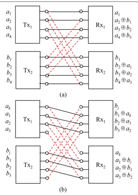
In a multi-user symmetric interference channel, all the direct-link channel gains are identical and so are the cross-link gains. As shown in Fig. 7, for a K-user symmetric interference channel, each user receives interference from otherK−1 users. Due to the symmetry, at each receiver,
Fig. 6An example to illustrate the feasibility.aSubchannelS1.b
SubchannelS2
Fig. 7A three-user parallel symmetric interference channel.
aSubchannel I.bSubchannel II
the interference signal levels are aligned. If we view the aligned interference as coming from a virtual user, the joint coding and decoding in the multi-user case can be implemented as same as in the two-user case.
K − 1 users as coming from one virtual user. Figure 7 is an example of a three-user parallel symmetric inter-ference channel, where only two subchannels are shown. Subchannel I is a weak interference subchannel, and sub-channel II is a strong interference subsub-channel. In subchan-nel I, as can be seen in Fig. 7a, the modulo-2 addition of a2⊕b1⊕c1=r12is received on the second level of Rx1, wherea2is the desired bit andb1⊕c1is the interference bit. We can regardb1⊕c1as one bitu1that is transmit-ted by a virtual user Txu. Then, we obtain an equation
a2⊕u1=r12. In subchannel II, as can be seen in Fig. 7b, b1andc1are retransmitted by Tx2and Tx3, respectively, and the virtual interference bitu1=b1⊕c1will reappear at Rx1with a desired bital, wherealis a retransmission bit
that causes interference in another weak interference sub-channel which is not shown here. Then, we obtain another equational⊕u1=r12 . Since the levels of interfering bits are always lower than the levels of desired bits in weak interference subchannels and vice versa for strong inter-ference subchannels at receivers, even thougha2 is also retransmitted in this strong interference subchannel, the relative level order ofal anda2 cannot be equal at Tx1. Thus, the two equationsa2⊕u1=r12andal⊕u1=r12 are linear uncorrelated. Then, the desired bits of user 1 can be jointly decoded at Rx1. Similar equations can be obtained at Rx2and Rx3, and in this way, we generalize the joint coding scheme to multi-user parallel symmetric interference channels.
5 Performance analysis
In the proposed joint coding scheme, the resource of strong interference subchannels are totally sacrificed to help the weak interference subchannels to achieve interference-free transmission, since no new bits are transmitted in strong interference subchannels. Then, a natural question is that under what conditions will this scheme have performance gain over the individual cod-ing? Is this scheme optimal? We answer these questions in this section.
5.1 Sum capacity
Theorem 1For two-user parallel symmetric interfer-ence channel with deterministic model, when the number of cross-link levels in weak interference subchannels equals to that in strong interference subchannels, the joint coding scheme will achieve the sum capacity
C =
s∈Sweak
2ns, (13)
where Sweak represents the set of weak interference
sub-channels, s denotes a weak interference subchannel in Sweak, and nsdenotes the number of direct-link signal levels
in subchannel s.
ProofWe first prove the converse by deriving the sum-rate constraints and then prove the achievability by pro-viding the achieved sum rate of the joint coding scheme.
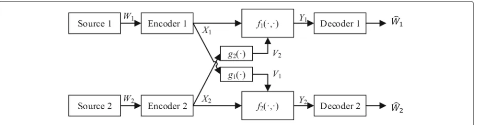
Converse The deterministic model of two-user paral-lel symmetric interference channel belongs to a class of deterministic interference channel studied by El Gamal and Costa [18]. The El Gamal-Costa model is redrawn in Fig. 8, where the outputsY1andY2and the interferences V1 andV2 are deterministic functions of the inputs X1 andX2:
for all product probability distributions onX1X2.
In the considered parallel symmetric interference chan-nel, X1 represents the transmit bits of all subchannels of user 1,g1(X1) represents the cross-link shifting func-tion overX1, andf1(X1,V2) represents the function that involves direct-link shifting over X1 and modulo-2 sum withV2. Similar representations are applied toX2,g2(X2), andf2(X2,V1). In (15), the conditional entropy ofY1over X1equals to the entropy ofV2, which means thatX1can be uniquely identified from Y1 given a determined V2. Similarly,X2can be uniquely identified fromY2given a determinedV1.
The capacity region of this class of deterministic inter-ference channel is characterized as [18]
R1≤H(Y1|V2),
Considering that there are totallySsubchannels, due to the symmetric property of each subchannel, we denote the number of direct-link signal levels of thesth subchannel asnsand the number of cross-link signal levels asms.
Fig. 8El Gamal and Costa’s deterministic interference channel model
Similar results hold forY2. Substituting these results in (16), we can obtain the sum-rate constraints as
R1+R2≤H(Y1|V1V2)+H(Y2)
Considering that in weak interference subchannels,ns>
msand, in strong interference subchannels,ns <ms, (21)
can be further expressed as
R1+R2≤
where Sweak and Sstrong represent the set of weak and strong interference subchannels, respectively.
Similarly, (22) can be further expressed as
R1+R2≤
where Snoisy represents the set of weak interference subchannels satisfyingms/ns < 1/2,Smediumrepresents
the set of weak interference subchannels satisfying 1/2≤ ms/ns < 1, andSstrongrepresents the set of strong inter-ference subchannels satisfyingms/ns≥1.
Since the number of cross-link signal levels in weak interference subchannels equals to that in strong interfer-ence subchannels, i.e.,
then (23) can be simplified as
R1+R2≤
s∈Sweak
2ns, (26)
and (24) can be simplified as
R1+R2≤
According to the relationship ofms andns in medium
weak interference subchannels, the second term in the last step of (27) is no less than zero, indicating that the con-straint (26) is stricter than (27). Thus, the active sum-rate constraint is (26).
AchievabilityFor the proposed joint coding scheme, in weak interference subchannels, users transmit new bits regardless of interference and, in strong interference sub-channels, only interfered bits are transmitted. Since the number of cross-link signal levels in weak interference subchannels equals to that in strong interference sub-channels, the received bits can be jointly decoded. The achieved sum rate of two users is
R1+R2=
s∈Sweak
Comparing (28) with (26), we conclude that the joint coding scheme achieves the sum capacity.
Theorem 2For K-user parallel symmetric interference channel with deterministic model, when the number of cross-link levels in weak interference subchannels equals to that in strong interference subchannels, the joint coding scheme achieves a sum rate
R =
s∈Sweak
K ns. (29)
The proof of Theorem 2 is the same as proving the achievability part in Theorem 1.
While the achievable sum rate ofK-user parallel sym-metric interference channel with deterministic model has been obtained, we do not know the sum capacity of this channel yet. However, we conjecture that the proposed joint coding scheme achieves the sum capacity, since each user achieves a data rate as high as in the two-user inter-ference channels.
5.2 Achievable GDoF
To obtain an explicit expression of the achievable GDoF and compare it with the individual coding scheme, we consider a special case of the parallel symmetric inter-ference channel. Assume that the number of direct-link signal levels are n for all the subchannels; the number of cross-link signal levels in weak interference subchan-nels arem1, and those in strong interference subchannels are m2. The interference strength of the two kinds of subchannels can be expressed as
α1= m1
n <1, α2= m2
n >1.
For the proposed joint coding scheme,α1strong inter-ference subchannels can assistα2weak interference sub-channels. For convenience of demonstration, the number of weak interference subchannels is normalized to 1. In this sense, we say one strong interference subchannel can assist to recover the contaminated bits in α2/α1 weak interference subchannels. For two-user case, according to Theorem 1, the sum capacity of these (α2/α1 + 1)
Then, with (8), the GDoF per user is
dJoint(α1,α2)= αα2 1
. (31)
For multi-user case, since the achieved sum rate is (29), the joint coding scheme achieves the per user GDoF as same as (31). That means, inK-user parallel symmetric interference channels, each user achieves a GDoF which
is the same as that can be achieved in two-user interfer-ence channels. Thus, for multi-user case, the joint coding scheme is at least GDoF optimal.
5.3 GDoF gains
We continually consider the scenario where one strong interference subchannel is used to assistα2/α1weak inter-ference subchannels. By individual coding, the GDoF of the strong interference subchannel isd(α2)and the GDoF of the weak interference subchannel isd(α1). Then, the total GDoF of these(α2/α1+1)subchannels per user is
dIndiv(α1,α2)= αα2 1
d(α1)+d(α2), (32)
whered(α1)andd(α2)can be obtained from (11). Compared with the achieved GDoF by joint coding, the average GDoF gain per subchannel in each user is
d(α1,α2)= see that we are able to provide positive GDoF gain when we use very strong interference subchannels to assist all kinds of weak interference subchannels and use moder-ately strong interference subchannels to assist noisy weak interference subchannels and fairly weak interference subchannels. However, when we use moderately strong interference subchannels to assist moderately weak inter-ference subchannels, no gain can be obtained. Besides, when using very strong interference subchannels to assist moderately strong interference subchannels, we can still obtain positive gain under certain conditions, although this is not the typical scenario that we have studied.
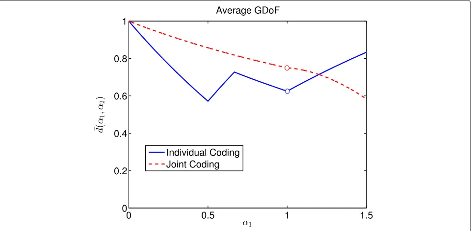
5.4 Numerical results
To demonstrate the GDoF gain, we provide some numer-ical results in this part. We first calculate the average achievable GDoFs when one strong interference subchan-nel coexists withα2/α1weak interference subchannels. In this example, we fixα2 = 3 and changeα1from 0 to 1.5. Of course, whenα1>1, the channel no longer belongs to weak interference subchannel. But by setting the param-eter in this range, we can obtain more useful insights. Figure 9 shows the results, where the “W” form solid line in blue represents the performance of individual coding and the red dash line represents the performance of the proposed joint coding. Note the blue solid line in Fig. 9 is not so straight as the one in Fig. 4. This comes from the fact that the result in Fig. 9 is obtained by averaging among
α2/α1+1 subchannels. It can be seen in Fig. 9 whenα1∈
Table 1Average GDoF gain per subchannel
d(α1,α2) α2∈(1, 2) α2∈(2,+∞)
α1∈(0,12) 2(αα11+α2α2)∈(0, 1
5) (α2−
1)α1 α2+α1 ∈(0,
1 2)
α1∈(12,23) 2α2α2−1+3α2α1α22 ∈(0, 1
5) α2−αα22+αα1−1α1∈(0,
1 2)
α1∈(23, 1) 0 α1(α2−
2) 2(α2+α1)∈(0,
1 2)
α1∈(1, 2) – α1(2α22(α−2α+1αα21−)2α1)∈(−43,12)∗
∗d>0 whenα2> 2α1
2−α1
still positive within a certain range. Only whenα1is larger, the gains become negative. This result indicates that, even when all the subchannels experience strong interference, it still has chance to improve the average achievable GDoF if we use very strong interference subchannels to assist strong interference subchannels.
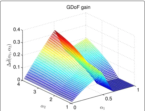
Now, we provide a more comprehensive result in Fig. 10, where α1 varies from 0 to 1 and α2 varies from 1 to 4. In this figure, only GDoF gain is drawn, from which the dependency of the gain d over different α1 and
α2 can be seen more clearly. For a fixedα1, d grows monotonically with α2. This result comes from the fact that the more cross-link signal levels can be used to employ retransmission in the strong interference sub-channel, the more weak interference subchannels can be assisted. For a fixed α2, dvaries like anN-curve, first increases when 0 < α1 < 12, then decreases when
1
2 < α1 < 23, and finally increases again when 23 <
α1 < 1. This is mainly because of the behavior ofd(α1) achieved by the individual coding, as can be seen in Fig. 4. When 0 < α1 < 1,d(α1)is a reverse N-curve.
In the cases when the individual coding can achieve high GDoF, the gain of joint coding is relatively low.
In [17], only the subchannels in very strong interference can help to recover the signals for subchannels in strong and weak interference. While in this paper, from the above analysis, we know that the proposed joint coding scheme can also let the strong interference subchannel help the weak interference subchannel. Moreover, only two-user case is considered in [17], but K-user case is also con-sidered in this paper. In [17], the interference channel is assumed to be bursty, and the helping mechanism cannot work when the channel is constant. However, the scheme proposed in this paper always works no matter the chan-nel is constant or bursty. In particular, when the chanchan-nel is bursty, different time slots can be regarded as different subchannels.
6 Conclusions
In this paper, a general joint coding scheme in par-allel symmetric interference channel with deterministic model was proposed where the cross-links of the strong
Fig. 10GDoF gains with differentα1andα2
interference subchannels were effectively used to assist interference mitigation in weak interference subchannels. We proved that this joint coding scheme can achieve the sum capacity in two-user case and can achieve the GDoF in multi-user case. Numerical results demonstrated sub-stantial GDoF gains over the individual coding scheme.
Acknowledgements
This work was supported by the National Natural Science Foundation of China under Grants 61371077 and 61429101. The authors would like to thank the anonymous reviewers for their constructive comments, which helped a lot to improve the presentation of this paper.
Competing interests
The authors declare that they have no competing interests.
Publisher’s Note
Springer Nature remains neutral with regard to jurisdictional claims in published maps and institutional affiliations.
Received: 9 November 2015 Accepted: 6 March 2017
References
1. ST Chung, JM Cioffi, The capacity region of frequency-selective Gaussian interference channels under strong interference. IEEE Trans. Commun. 55(9), 1812–1821 (2007)
2. W Yu, G Ginis, JM Cioffi, Distributed multiuser power control for digital subscriber lines. IEEE J. Sel. Areas Commun.20(5), 1105–1115 (2002) 3. W Yu, R Lui, Dual methods for nonconvex spectrum optimization of multicarrier systems. IEEE Trans. Commun.54(7), 1310–1322 (2006) 4. VR Cadambe, SA Jafar, Parallel Gaussian interference channels are not
always separable. IEEE Trans. Inf. Theory.55(9), 3983–3990 (2009) 5. X Shang, B Chen, G Kramer, HV Poor, Noisy-interference sum-rate capacity
of parallel Gaussian interference channels. IEEE Trans. Inf. Theory.57(1), 210–226 (2011)
6. H Sun, SA Jafar, inISIT. On the optimality of treating interference as noise for parallel deterministic interference networks, (2014)
7. L Sankar, X Shang, E Erkip, HV Poor, Ergodic fading interference channels: sum-capacity and separability. IEEE Trans. Inf. Theory.57(5), 2605–2626 (2011)
8. TS Han, K Kobayashi, A new achievable rate region for the interference channel. IEEE Trans. Inf. Theory.27(1), 49–60 (1981)
9. RH Etkin, DNC Tse, H Wang, Gaussian interference channel capacity to within one bit. IEEE Trans. Inf. Theory.54(12), 5534–5562 (2008)
10. SA Jafar, S Vishwanath, Generalized degrees of freedom of the symmetric GaussianKuser interference channel. IEEE Trans. Inf. Theory.56(7), 3297–3303 (2010)
11. SA Jafar, Topological interference management through index coding. IEEE Trans. Inf. Theory.60(1), 529–568 (2014)
12. C Suh, DNC Tse, Feedback capacity of the Gaussian interference channel to within 2 bits. IEEE Trans. Inf. Theory.57(5), 2667–2685 (2011) 13. S Mohajer, R Tandon, HV Poor, On the feedback capacity of the fully
connectedK-user interference channel. IEEE Trans. Inf. Theory.59(5), 2863–2881 (2013)
14. Y Wang, Y Tian, C Yang, C Sun, inPIMRC. Multi-carrier cooperated interference cancelation in heterogeneous cellular networks, (2013) 15. N Hou, Y Tian, C Yang, inICCC. Multi-carrier cooperated interference
cancellation via macro-BS broadcasting in HetNet, (2014)
16. P Mukherjee, R Tandon, S Ulukus, inAllerton Conf. Even symmetric parallel linear deterministic interference channels are inseparable, (2013) 17. S Mishra, I Wang, S Diggavi, inISIT. Harnessing bursty interference in
multicarrier systems with feedback, (2014)
18. AA El Gamal, MHM Costa, The capacity region of a class of deterministic interference channels. IEEE Trans. Inf. Theory.28(2), 343–346 (1982) 19. S Saha, R Berry, inAllerton Conf. Sum-capacity of a class ofK-user
Gaussian interference channels withinO(K) bits, (2011)
20. D Maamari, D Tuninetti, N Devroye, Multi-user cognitive interference channels: a survey and new capacity results. IEEE Trans. Cogn. Commun. Netw.1(1), 29–44 (2015)
21. S Gherekhloo, A Chaaban, A Sezgin, Cooperation for interference management: a GDoF perspective. IEEE Trans. Inf. Theory.62(12), 6986–7029 (2016)
22. R Kolte, A Özgür, H Permuter, Multicoding schemes for interference channels. IEEE Trans. Inf. Theory.62(9), 4936–4952 (2016)
23. M Kiamari, A Avestimehr, inAllerton Conf. Are generalized cut-set bounds tight for the deterministic interference channel? (2015)
24. S Avestimehr, S Diggavi, DNC Tse, Wireless network information flow: a deterministic approach. IEEE Trans. Inf. Theory.57(4), 1872–1905 (2011) 25. G Bresler, A Parekh, DNC Tse, The approximate capacity of the
many-to-one and one-to-many Gaussian interference channels. IEEE Trans. Inf. Theory.56(9), 4566–4592 (2010)
Submit your manuscript to a
journal and benefi t from:
7Convenient online submission
7Rigorous peer review
7Immediate publication on acceptance
7Open access: articles freely available online
7High visibility within the fi eld
7Retaining the copyright to your article