R E S E A R C H
Open Access
Green radio despite
“
Dirty RF
”
front-end
Myriam Ariaudo
1*, Inbar Fijalkow
1, Jean-Luc Gautier
1, Mathilde Brandon
1,2, Babar Aziz
1and Borislav Milevsky
1Abstract
In this article, we show that the non-ideal Radio-Frequency (RF) front-ends have to be corrected in order to contribute in a Green radio development. In fact, the effects of typical RF imperfections, like nonlinearities, carrier frequency offsets, and IQ imbalances, can be compensated for, when digital correction algorithms are applied. Such algorithms enable Green applications (e.g., Orthogonal Frequency Division Multiple Access for the uplink) despite a restrictive RF imperfection, or allow a less constrained hardware design, which reduces the chip area and the number of components (Green design) or facilitate the reduction of spectral pollution and of power
consumption (Green transmission). So, we propose to implement these correction methods to compensate for the damaging effects of RF imperfections in mind of a Green issue.
Keywords:communication electronic systems and components, interference reduction, RF imperfections compen-sation, RF nonlinearity, carrier frequency offset, agile multiband synthesizer
Introduction
It is now well established that the optimization of the performance of the whole communication system has to consider the effect of its Radio-Frequency (RF) front-end to avoid a waste of resources and a huge margin in design. This requirement becomes particularly important due to the increasing use of complex dynamic signals, like Orthogonal Frequency Division Multiplexing (OFDM). Such signals are necessary to improve the sys-tem performance in hostile environment or to develop reconfigurable systems for cognitive radio. Concerning the RF part, designing a Green radio first consists in the improvement of efficiency. It is well known that the most power-consuming circuit is the power amplifier (PA) of the transmitter of handset systems as well as of the base station [1]. Many authors have considered this issue in particular since complex modulations with non-constant envelope signals are employed.
On top of that, the RF front-end limits the performance of the transmission because of its imperfections. Indeed the performance is affected by various RF imperfections like nonlinearities, frequency offset between the transmit-ter and the receiver, phase noise of local oscillator, IQ imbalance, etc. These RF imperfections and their impacts have been reported in a new concept referred as“Dirty
RF”by Fettweis et al. [2]. In recent years, several parts of the RF front-end have been considered to evaluate the overall performance of a communication system, and digi-tal methods have been developed to compensate for their damaging effects and then to improve the performance of a given non-ideal system.
In this article, we show how the correction of RF front-end imperfections can participate in the design of Green radio. Some of these corrections enable a Green transmis-sion (in the sense of the reduction of spectral pollution and energy consumption) or a Green application (like Orthogonal Frequency Division Multiple Access–OFDMA in the uplink); other corrections allow to reduce the chip area and the number of circuit components, and thus allow a Green production. So, in the sequel, we give some examples to show that the application of our correction methods can help in the compensation of the effect of RF circuit imperfections in different Green objectives.
Green radio despite “Dirty RF physical implementation”thanks to digital correction One Green objective for the RF front-end can be to mini-mize the chip area and the number of components. To achieve this objective, a transmission system with direct frequency conversion is a good solution. Unfortunately, such systems are more sensitive to some RF imperfections, like IQ imbalance in the modulator/demodulator or car-rier frequency offsets (CFOs) (due to a higher frequency of
* Correspondence: myriam.ariaudo@ensea.fr 1
ETIS/ENSEA–Université Cergy-Pontoise-CNRS, 6 avenue du Ponceau, Cergy 95000, France
Full list of author information is available at the end of the article
the local oscillator). The consequences are a degradation of the performance, which has to be compensated for.
It is well known that the IQ imbalance can be mod-eled by a mismatch of the phasedue to an imprecise phase quadrature and/or by a mismatch of the gain g due to different mixer characteristics between the two branchesIandQ.
For the transmitter case (Figure 1) at the transposed frequencyfOL, the equivalent base band signal affected by the IQ imbalance can be written in the frequency domain as
where FeIk and FeQk are the I and Q frequency
responses on the band,k is the carrier index (particu-larly in the case of an OFDM signal), n is the symbol index, and Ek(n) is the initial symbol to be transmitted. The gain of the PA is considered to be linear and equal to 1 in this equation.
TheIQimbalance causes interference between the two branches. Furthermore, the received signal is affected by the propagation channel and the receiver noise. A simi-lar model takes into account the IQ imbalance at the receiver.
In order to compensate for these degradations, the receiver needs to jointly estimate the channel response and the imbalance characteristics before correcting the received symbols.
Many methods have been proposed to compensate for theIQimbalance effect but generally the complexity of such methods is high or their application requires modi-fications of standards. Recently, we have developed a digital correction method, presented in [3], that gives good performances with a low complexity, even for large mismatches. Applying this algorithm to a 64QAM-OFDM signal (like in HiperLAN2) allows for example to accept:
- an IQ imbalance at the transmitter up to 10° in phase and 20% in gain with a degradation of the Sig-nal-to-Noise ratio (SNR) less than 2 dB for a fixed uncoded BER of 10-2;
- anIQimbalance at the receiver up to 30° in phase and 100% in gain with a degradation of the SNR less than 1.5 dB for a fixed uncoded BER of 10-2.
This example shows that it is then possible to relax constraints on the implementation because the phase variation induces a possible variation of the branches length, leading to a reduction of the chip area. For a
carrier frequency in the GHz range, a phase of several degrees corresponds to a length of several millimeters.
The ability of efficiently correcting the effect of theIQ imbalance (frequency selective or not) facilitates to accept an imperfect physical implementation with a reduced chip area. That is a way to help in the design of a Green radio especially in the case of a direct-conver-sion system.
Green radio despite“Dirty RF amplifier”thanks to channels pollution reduction method
One Green objective for the RF front-end is to minimize the spectral pollution of adjacent channels.
At the same time, it is necessary to optimize the trans-mitter efficiency, for the base station as well as handsets. To benefit from a large PA efficiency, it is necessary to operate near the nonlinear zone, degrading consequently the linearity of the whole system. This brings a particular disadvantage for non-constant envelope signals. It is then necessary to compensate for that by applying a lineariza-tion method or a signal dynamic reduclineariza-tion to avoid the pollution of neighboring channels.
Though many studies have dealt with this issue, apply-ing such techniques separately is not sufficient, in parti-cular in the case of complex signals like OFDM, which present a large dynamic. The combination of these methods seems promising [4] as long as the complexity is not dramatically increased.
In our recent studies [5], we have combined (Figure 2) a linearization method, usually called“Digital Predistor-tion”(DPD), and a Peak-to-Average Power Ratio (PAPR) reduction technique called“Active Constellation Exten-sion”(ACE) method. This combination has not yet been studied before, and it allows to improve the linearity per-formance without degradation of the bit error rate (BER).
Measurements have been made on a real amplifier to prove its efficiency.
The ACE method is well suited, as it is dedicated to OFDM signals. Moreover, compared to other methods, it allows to improve the out-of-band performance without degrading the in-band performance. The ACE method makes it possible to modify the constellation of the digital modulation of OFDM symbols to reduce their dynamic without degrading the BER. The ACE is an iterative pro-cess, which requires one extra FFT algorithm. However, the development of the digital circuits allows the imple-mentation of the ACE with increasing efficiency [6].
The DPD of the input signal by a function that approximates the inverse of the nonlinearity is the most popular linearization method. In our case, the“ predis-tortion function” is determined based on the amplifier output (path 1 in Figure 2), and it is modeled using a memory polynomial expression. As this algorithm com-putes directly the predistorter characteristic, it is less complex than those that need to evaluate the amplifier characteristic before inverting it.
The predistortion function is then applied to the OFDM signal, of which the PAPR has been reduced. This predistorded OFDM signal is supposed to be nearly linearly amplified when passing through the amplifier (path 2 in Figure 2).
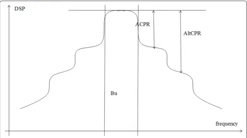
To evaluate the impact of the method, the Adjacent Channel Power Ratio (ACPR) and Alternate Channel Power Ratio (AltCPR) (Figure 3) are measured. They indicate the pollution in direct adjacent channels (ACPR) and next ones (AltCPR), by comparing it to the power in the signal bandwidth (Bu). The largest ACPR and AltCPR correspond to the lowest pollution.
Validated for a simulated nonlinear amplifier, our algorithm has been first applied to a real amplifier (GaN
PA polarized in AB-class) for a QPSK-OFDM signal [5]. Figure 4 shows the test bench used to measure the spec-trum at the output of the amplifier (calledBoosterin the figure).
The following figures present the comparison of the new results in terms of ACPR (Figure 5), and AltCPR (Figure 6) measured at the amplifier output versus the output power, obtained for a 16QAM-OFDM signal with 5-MHz bandwidth. The labels“ACE”or “no ACE” refer to the case where the ACE method is applied or
not; the labels “DPD” or “no DPD” refer to the case where the DPD method is applied or not.
These new measurement results confirm an improve-ment of the linearity performance, compared to the cases where the two methods are applied separately, in the immediate adjacent channels as well as in the next ones. Indeed better ACPR and AltCPR performances are obtained when ACE and DPD are jointly applied (red curve). For example, for an output power of 42 dBm, the ACPR is improved by 17 dB compared to the initial
Figure 3ACPR and AltCPR display.
case (without ACE and DPD) and the AltCPR is improved by 12 dB. Moreover, for a target ACPR, the work point can be pushed near the saturation zone of the amplifier to achieve a better efficiency. These results are obtained in a more sensitive case (16QAM-OFDM) than in [5] (QPSK-OFDM) proving the robustness of our method.
So, we showed that the combination of these two methods allows to reduce the pollution of both the adja-cent and the following channels and thus it helps in the deployment of Green radio systems. Indeed, not only the transmitter efficiency of the considered user is
improved, but also the adjacent users are less interfered. Furthermore, BER measurements have shown negligible degradations after the application of the predistortion and ACE methods.
Green radio despite “Dirty RF synthesizer”thanks to interferences reduction method
Another Green objective of new communication systems is to be flexible. However, band and sub-band flexibility leads to an increase of the sensibility to the RF imper-fections or to complex RF front-ends. In the following, we show two examples for the case where interference
Figure 5ACPR measurements versus amplifier output power.
reduction methods permit to deploy efficient Green sys-tems due to the reduction of the effect of various RF imperfections of the frequency synthesizer.
OFDMA in uplink systems for Green radio
OFDMA is an adaptation of the well-known OFDM sys-tem that enables to share the spectrum between several users based on a Carrier Allocation Scheme. It is well adapted for Green radio systems as it allows optimized resource and power allocations, with great flexibility, leading to an efficient transmission [7]. Well established for downlink transmission, OFDMA has not yet been chosen for uplink transmissions because the synthesizer in the RF front-end at the transmitter (mobile handset) is not ideal enough and causes interferences between the sub-carriers of received signals at the base station. Figure 7 shows the model of the emitter affected by a CFO resulting from the oscillator frequency mismatch of the emitters.
In a recent study [8], we have developed a model that takes into account the CFO between each user and the base station. The signal at the output of the transmitter of userucan be written as
x(u)(t) =Re response of the filter at the transmitter,T is the symbol period of an OFDMA symbol,Npis the total number of
subcarriers, and ak(u) are the symbols after the output
of the inverse DFT.
The received signal at the base station is the sum of the signals from each user affected by their respective channels. As it has been shown in [8], at the output of the DFT block the vector of the received signals can be written as
R=Nu
u=1G
(u)A(u) (5)
where R,an Np × 1 vector containing the samples of the received signals,A(u) = F-1 a(u), the vector of trans-mitted modulation symbols of user u after subcarrier mapping with F, theNp×NpDFT matrix,G(u), theNp ×Npchannel matrix that can be expressed as
G(u)=H(u)Fδ(u)F−1+ (δ−Np(u)−1)Fh(u)
δ(u)F−1 (6)
withH(u), the diagonal DFT channel matrix for a user
u, δ(u), a diagonal matrix of the shift coefficients
lar matrix involving the channel impulse response due to the effect of the CFO on the cyclic prefix (this term is usually neglected in the literature).
As opposed to other models, like [9], our model of the received signal takes into account the effect of the CFO on the cyclic prefix. This makes the model more realis-tic and improves the channel estimation [10].
Based on this model, we propose to correct the effect of the CFO in presence of estimated channels. This correc-tion will lead to the suppression of most interference at the receiver and allows to deploy OFDMA in uplink trans-missions. For the sake of simplicity we allocateK=Np/Nu subcarriers to each of theNu users. Adapted from the Serial Interference Cancellation (SIC) algorithm, we pro-pose to divide the blocksG(u)of sizeK×Kinto smaller blocks of sizeS×S, called the inner-blocks, whereNs=K/
S. Only theS×Sblocks are inverted to cancel the interfer-ence, which reduces considerably the interference cancel-lation complexity (see Table 1). We call this method the self-SIC method. Figure 8 shows new results for the per-formance in presence of CFO and their improvement due to our self-SIC algorithm. The normalized CFOδf(u)is obtained by the ratio of the CFOδfc(u) and the subcarrier
spacingΔf, i.e., δf(u)=δfc(u)/f. The simulation is based
on IEEE 802.11a specifications deployed forNu= 4 users,
Np= 256 subcarriers,K=Np/Nu= 4, a cyclic prefix of lengthLcp=Np/4 = 64, and an SNR of 15 dB.
The BER performance is improved due to the self-SIC method, which reduces the interference at the receiver. Up to a normalized CFO of 0.3, the BER of 10-2is practically maintained. A normalized CFO ofδf(u)= 0.3 corresponds in this example to ± 20 ppm stability at 5 GHz; this range ofδf(u)corresponds to realistic characteristics of an actual VCO.
Various simulated cases show that the quality of improvement does not depend on the block-size used for each user. This makes our algorithm very competitive in terms of complexity compared to other methods. As an example, the interference cancellation method described in [11] depends on the block-sizeKand as a consequence its complexity increases with the block-size. Indeed, large block-sizesK×Krequire the implementation of the inver-sion of largeG(u)matrices. Table 1 compares the compu-tational complexity of our proposed self-SIC method to that of the interference cancellation method proposed in [11].
It is clear that our proposed self-SIC overcomes the disadvantage of large matrix inversions, especially when the number of sub-carriers in the block is large.
So, we prove that despite a mismatch in the low-cost RF front-end synthesizers, it is possible to deploy OFDMA in an uplink transmission due to a not so costly digital correction. This dirty RF model and new
digital correction is a suggestion for a Green flexible system.
Optimized multi-band synthesizer for Green radio
In the context of modern Green communications, it is important to allow frequency band hoping to benefit from frequency diversity for each user or from multi-mode running. However, the required frequency synthe-sizer can suffer from high complexity, as it needs to fulfill the constraints necessary to avoid interference between the users. Based on the example of the MB-OFDM (multi-band OFDM) standard [12] with very strict con-straints, we have studied and developed an agile fre-quency synthesizer, able to switch between 14 frefre-quency bands between 3.432 and 10.296 GHz [13]. It requires only one phase locked loop (PLL); the frequencies are generated by consecutive mixing and selection between different outputs of the PLL.
This architecture allows a switch time less than 10 ns. Imperfections of the components, however, like mixer or multiplexer leakages, or mixer nonlinearities, lead to the generation of spurious frequencies when one of the 14 frequencies is selected. To generate as few spurs as possible, several filters have to be added after the mix-ers; they are designed to minimize the total spurious power, which must be at least 24 dBc lower than the power of the generated frequency to ensure a good SNR at the receiver. Table 2 shows the spur levels generated in the case of the most constraining frequencies without band-pass filter after mixers and those obtained with suitable band-pass filters. The results prove the positive impact of the filters.
However, the system can be optimized in terms of the surface area and the number of components if a compen-sation algorithm is applied to reduce the interference at the receiver produced by the spurs. We have shown, in an uplink transmission, that a SIC algorithm applied at the receiver can improve the performance [14]. With the developed method, it is possible to tolerate a level between total spurious power and the generated fre-quency of 17 dBc (instead of 24 dBc) with a degradation of the SNR less than 0.1 dB. As shown in Table 2, this minimum level is not reached without a filter, except for the channelQof 9768 and 10296 MHz, for which the level is nevertheless very close to 17 dBc.
This result shows that the filters may be removed because the associated degradation can be compensated
Table 1 Complexity of our algorithm compared to [11]
Self-SIC algorithm Cancellation algorithm in [10]
Complexity O(NsS3) O(K3) withK=NsS
for. The BER at the receiver will not be increased due to the reduction of the induced interferences.
Therefore, we propose to simplify the synthesizer architecture by removing the pass-band filters after the mixers I, II, III, and IV (Figure 9).
In such a complex structure, removing the filters is an efficient way to reduce the RF system complexity and to optimize the chip surface with regard to a Green objec-tive for the uplink transmission.
Conclusion
Though the RF front-end has often been considered as a degrading part of the system because of its“dirty” char-acteristics, it has to be taken into account in the devel-opment of a Green radio: the imperfections of RF front-end can either be minimized, or they can be compen-sated for. The examples presented in this article prove that it is possible to tolerate RF imperfections, as the performance can greatly be improved by digital correc-tion methods. This leads to either more efficient trans-mission in terms of power consumption or spectral
Figure 8Performance comparison with and without interference cancellation.
Table 2 Difference between the power of the main frequency and the total spurs power in dBc (has to be greater than 24 dBc)
Frequency (MHz) Without band-pass filter With band-pass filter Channel I Channel Q Channel I Channel Q
8184 18.331 19.031 24.3 27.7
8712 18.745 17.879 24.1 27.1
9240 19.446 18.634 31.8 31.8
9768 17.457 16.673 29.6 25.9
pollution, or to a smaller and less complex radio front-end. Both approaches contribute to a Green radio.
Acknowledgement
The authors would like to thank Jessica Bouvier and Sylvain Traverso of THALES Communications for their participation in the amplifier predistortion study, and the French Ile de France Region DIM for supporting the study on OFDMA uplink through the DESAP project.
Author details
1ETIS/ENSEA–Université Cergy-Pontoise-CNRS, 6 avenue du Ponceau, Cergy 95000, France2THALES COMMUNICATIONS, 160 Bd de Valmy, 92704 Colombes cedex, France
Competing interests
The authors declare that they have no competing interests.
Received: 30 September 2011 Accepted: 18 April 2012 Published: 18 April 2012
References
1. LM Correia, D Zeller, O Blume, D Ferling, Y Jading, I Godor, G Auer, L Van de Perre, Challenges and enabling technologies for energy aware mobile radio networks. IEEE Commun Mag.48(11), 66–72 (2010)
2. G Fettweis, M Lôhning, D Petrovic, M Windisch, P Zillmann, W Rave, RF Dirty, a new paradigm. Int J Wirel Inf Netw.14(2), 133–148 (2007) 3. S Traverso, M Ariaudo, I Fijalkow, JL Gautier, C Lereau, Decision directed
channel estimation and high I/Q imbalance compensation in OFDM receivers. IEEE Trans Commun.57(5), 1246–1249 (2009)
4. A Bo, Y Zhi-xing, P Chang-yong, Z Tao-tao, G Jian-hua, Effects of PAPR reduction on HPA predistortion. IEEE Trans Consum Electron.51(4), 1143–1147 (2005)
5. M Brandon, M Ariaudo, S Traverso, J Bouvier, I Fijalkow, JL Gautier, Linearity improvement thanks to the association of active constellation extension and digital predistortion for OFDM, inProceedings of IEEE NEWCAS, Bordeaux, 293–296 (June 2011)
6. S Chen, C Yu, C Tsai, J Tang, A new IFFT/FFT hardware implementation structure for OFDM applications, inIEEE Asia-Pacific Conference on Circuit and Systems,Taiwan 1093–1096 (December 2004)
7. D Galda, R Gruenheid, H Rohling, OFDM: a flexible and adaptive air interface for a 4G mobile communication system, inInternational Conference on Telecommunications (ICT)Beijing, 5–14 (2002) 8. B Aziz, I Fijalkow, M Ariaudo, Intercarrier interference in uplink OFDMA
systems with carrier frequency offset, inPIMRCIstanbul, 476–751 (September 2010)
9. Z Cao, U Tureli, YD Yao, P Honan, Frequency synchronization for generalized OFDMA uplink, inProceedings of Globecom’2004 IEEE, Dallas,2, 1071–1075 (2004)
10. B Aziz, I Fijalkow, M Ariaudo, Joint estimation of channel and carrier frequency offset from the emitter, in an uplink OFDMA system”, inICASSP, Prague, 3492–3495 (May 2011)
11. T Yucek, H Arslan, Carrier frequency offset compensation with successive cancellation in uplink ofdma systems. IEEE Trans Wirel Commun.6(10), 3546–3551 (2007)
12. C Mishra, A Valdes-Garcia, F Bahmani, A Batra, E Sanchez-Sinencio, J Silva-Martinez, Frequency planning and synthesizer architectures for multiband UWB radios. IEEE Trans Microwave Theory Tech.53(12), 3744–3756 (2005) 13. S Traverso, M Ariaudo, JL Gautier, C Lereau, I Fijalkow, A 14-band low
complexity and high performance synthesizer architecture for MB-OFDM communication. IEEE Trans Circ Syst II.54(6), 552–557 (2007)
14. B Milevsky, M Ariaudo, JL Gautier, I Fijalkow, M Hristov, Successive interference cancellation (SIC) in MB-OFDM receiver with imperfect local oscillator, inEuMCParis, 385–388 (September 2010)
doi:10.1186/1687-1499-2012-146
Cite this article as:Ariaudoet al.:Green radio despite“Dirty RF” front-end.EURASIP Journal on Wireless Communications and Networking2012 2012:146.


![Table 1 Complexity of our algorithm compared to [11]](https://thumb-us.123doks.com/thumbv2/123dok_us/960291.1117677/7.595.58.528.692.731/table-complexity-algorithm-compared.webp)


