R E S E A R C H
Open Access
Improved progressive edge-growth algorithm for
fast encodable LDPC codes
Xueqin Jiang
1,2*, Moon Ho Lee
3and Jinpeng Qi
1,2Abstract
The progressive edge-growth (PEG) algorithm is known to construct low-density parity-check (LDPC) codes at finite code lengths with large girths by establishing edges between symbol and check nodes in an edge-by-edge manner. The linear-encoding PEG (LPEG) algorithm, a simple variation of the PEG algorithm, can be applied to generate linear time encodable LDPC codes whosemparity bitsp1, p2, ..., pmare computed recursively inmsteps. In this article, we propose modifications of the LPEG algorithm to construct LDPC codes whose number of encoding steps is independent of the code length. The maximum degree of the symbol nodes in the Tanner graph is denoted by dmax
s ; Themparity bits of the proposed LDPC codes are divided into dmaxs subgroups and can be computed in only dmax
s steps. Since dmaxs m, the number of encoding steps can be significantly reduced. It has also been proved that the PEG codes and the codes proposed in this article have similar lower bound on girth. Simulation results showed that the proposed codes perform very well over the AWGN channel with an iterative decoding.
1 Introduction
Low-density parity-check (LDPC) codes, which were first proposed in the early 1960’s [1] and re-discovered in 1996 [2], have recently attracted much attention due to their capacity-approaching performance and low decoding complexity. Since their re-discovery, there are many methods such as the message-passing decoding and the linear program decoding [3,4] that have been proposed for the decoding algorithm. Also many other methods have been proposed for the construction algo-rithm [5-8]. Among the existing methods, the most suc-cessful approach for the construction of LDPC codes is the progressive-edge-growth (PEG) algorithm [5,6]. The PEG construction builds up a Tanner graph, equivalent to a parity-check matrix, for an LDPC code in an edge-by-edge manner and maximizes the local girth at symbol nodes in a greedy algorithm. It is simple and flexible in that it can be applied in constructing codes of arbitrary length and rate. In addition, the PEG algorithm can be modified to construct linear time encodable LDPC codes. In this article, this modified algorithm is referred to as linear-encoding PEG (LPEG) algorithm. Initially,
the parity-check matrix was used in decoding process for LDPC codes. But it can also be used for the
encod-ing of LDPC codes [9]. LDPC codes withm parity bits
constructed by the LPEG algorithm can be encoded
with the parity-check matrix in mrecursive steps [6].
Therefore, for a given code rate R, the number of
encoding steps of LPEG codes grows linearly with the code lengthn=m/(1-R).
The objective of this article is to reduce the number of encoding steps of the LPEG codes with negligible performance loss. To reduce the number of encoding steps, we modified the LPEG algorithm to obtain two new algorithms which are referred to as fast-encoding PEG (FPEG) algorithm and modified FPEG (MFPEG)
algorithm, respectively. dmax
s is used to denote the
maximum degree of symbol nodes. The number of encoding steps of the FPEG codes grows linearly with
dmax
s , but not the code length n. The number of
encoding steps of the MFPEG codes grows linearly
with (dmaxs +
m dmax
s
−1). Since dmaxs is much smaller
than m, the number of encoding steps of FPEG codes
or MFEPG codes is lower than that of the LPEG codes. Moreover, to ensure that there is negligible per-formance loss, we proved that the PEG codes and our codes had similar lower bound on girth. This was
* Correspondence: [email protected]
1
Donghua University, School of Information Science and Technology, Shanghai, China
Full list of author information is available at the end of the article
confirmed by providing examples of the proposed codes and comparing their performance with that of the multiple serially concatenated multiple parity-check (M-SC-MPC) code, which is a class of LDPC codes of efficient encoding [10].
The remainder of this article is organized as follows. Section 2 reviews the PEG algorithm and the LPEG algorithm. Section 3 proposes the FPEG algorithm and the MFPEG algorithm. A lower bound on the girth of the FPEG algorithm is also derived in this section. Sec-tion 4 presents two examples of FPEG codes and MFPEG codes and demonstrates their performances. Finally, Section 5 concludes the article.
2 Preliminary
2.1 Progressive edge-growth algorithm
An LDPC code is a linear block code defined by a
sparse parity-check matrixHhaving dimension m×n.
A bipartite graph with mcheck nodes in one class and
nsymbol nodes in the other can be created usingHas
the integer-valued incidence matrix for the two classes. Such a graph is also called a Tanner graph [11]. Let Vc = {c0, c1, ...,cm -1} denote the set of check
constructing a Tanner graph withnsymbol nodes and
m check nodes is described in Algorithm 1. In this
algorithm, both symbol nodes and check nodes are ordered according to their degrees in a nondecreasing order. dsj is the degree of symbol node sj,Nlsj, and N¯sjl
denote the set of all check nodes reached by a tree spreading from symbol node sj with in depth l, and its complement, respectively [6]. It was proved that [4] the PEG algorithm constructs Tanner graphs having a large girth and the lower bound on the girth was proved to be
Algorithm 1. PEG algorithm
1: forj= 0 ton- 1do lowest check-node degree under the current graph set-ting Es0∪Es1∪ · · · ∪Esj−1.
4: else
expand a subgraph fromsj up to depth l
under the current graph setting such that the cardinality of Nl
sj stops increasing but is less thanm, or N¯lsj+1=∅
but N¯l+1
sj =∅, then Eksj ←edge (ci,sj), where Eksj is the kth edge incident on sj and ci is a check node picked from N¯lsj having the lowest check-node degree.
5: end if
c and dmaxs were the maximum degrees of
the check nodes and symbol nodes, respectively.
2.2 Linear-encoding PEG algorithm
It is stated [12] (Corollary 4) that if a parity-check
matrixHcan be transformed into an upper or lower
tri-angular matrix by row and column permutations, the corresponding LDPC code can be encoded in linear number of steps. Obviously, the PEG algorithm can also
be tailored to construct a parity-check matrixHhaving
upper triangular structure. The code word C and the
parity-check matrix H are partitioned into C = [p, d] andH= [Hp,Hd], respectively, such that
[Hp,Hd]CT= 0, (2)
where the m ×mcomponent Hp=hpi,j of the parity-check matrix is forced to have the upper
triangular form
tioned parity-check matrixHand ⊕represents the
sum-mation over binary field, i.e., an XOR operation. From
Equation (4), the m parity bits can be computed from
pm top1 serially in msteps. Therefore, the number of
encoding steps is
Accordingly, the symbol node set Vsin the Tanner graph is partitioned into redundant subset Vsp and the
information subset Vsd, which contain the firstm
sym-bol nodes and the other n- m symbol nodes,
respec-tively. The edges of the symbol nodes are then established by means of the LPEG algorithm which con-structs an upper triangular pattern. As the procedure of establishing the edges of n-minformation bits follows the construction of edges of Vp
s and is exactly the same
as the PEG algorithm described in Algorithm 1, only the
LPEG algorithm for constructing edges of Vsp is shown
in Algorithm 2.
Algorithm 2. LPEG algorithm for Establishing Edges of Vsp diagonal line of matrixHp.
4: else
expand a subgraph from sj up to depth l
under the current graph setting such that
¯
Note that the first column of Hp corresponds to a
degree-1 symbol node and the fraction of degree-1 sym-bol node is 1/n. It was proved that the Tanner graph of an upper or lower triangular parity-check matrix could be equivalently transformed into a pseudo-tree and the corresponding LDPC codes could also be encoded in a linear number of steps by the label-and-decide algorithm [12].
2.3 M-SC-MPC codes
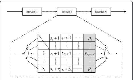
Let ni, ki, and ri denote the code length, information
length and parity-check length of the ith component
MPC code, respectively. The encoder of each
compo-nent MPC code can be implemented asriSPC encoders
as shown in Figure 1 [10]. The matrix cells of the ith
encoder are filled in column-wise order from top left to
bottom right. The firstri - si cells, with si =kmod ri, are unused. When the jth row is filled,j= 1, ...,ri, the parity bitpjis calculated by XORing the elements of the row, and its value is stored in the last column, at the same row. Each component MPC code can be seen as a shortened version of a binary cyclic code with length
Ni=
matrixHifor the ith component code, consisting of a
row of niri identity matrix with sizeri×ri. As the ith
component code has length ni, the cyclic code must be
shortened. This implied eliminating the first Ni -ni
col-umns of Hi.Hiforms a block-row of the parity-check
matrix H of the serially concatenated code.
Conse-quently, Hwas in the lower triangular form, consisting
of identity matrices and zero matrices. The serially
con-catenated code has information length k, parity-check
length m=Mi=1ri and code lengthn=k+m.
3 FPEG algorithm and MFPEG algorithm
In general, an ensemble of Tanner graphs is defined through degree distribution pairs. In the case of the symbol nodes, the degree distribution, from the edge perspective, is given by
ψ(x) =
where ψiis the fraction of Tanner graph edges which
emanate from degree-i symbol nodes. The fraction of
degree-i symbol nodes, from the node perspective, is
given by
Encoder 1 Encoder i Encoder M
1
Similarly, in the case of the check nodes, the degree distribution, from the edge perspective, is given by
ϕ(x) =
where i is the fraction of Tanner graph edges which
emanate from degree-i check nodes. The fraction of
degree-i check nodes, from the node perspective, is
given by
In the following section, we introduce an FPEG algo-rithm and an MFPEG algoalgo-rithm used to construct an upper triangular parity-check matrix.
3.1 FPEG algorithm
Example 1: Consider the parity-check matrix in (10),
H= [Hp,Hd] =
no means a good LDPC code but it is an example. The
parity-check matrix Hin (10) can be divided into three
2 × 12 submatrices H1, H2 and H3. In each submatrix
Hi, the rows do not have‘1’s in the same column. Then, the encoding ofCincludes the following three steps:
Step 1Given the submatrix H3 and the information
bitsd1, d2, ...,d6, compute the parity bits p5,p6 by the
parity-check equations
p5=d1⊕d2⊕d4,
p6=d3⊕d5⊕d6.
(11)
Step 2Given the submatrix H2 and the information
bits d1, d2, ..., d6 and parity bits p5, p6, compute the
check bitsp3,p4 by the parity-check equations
p3=d1⊕d2⊕d3⊕p5,
p4=d4⊕d5⊕d6⊕p6.
(12)
Step 3Given the submatrix H1 and the information
bits d1,d2, ..., d6 and check bitsp3, p4, p5, p6, compute
the parity bitsp1,p2by the parity-check equations
p1=d1⊕d3⊕d5⊕p4⊕p5,
p2=d2⊕d4⊕d6⊕p3⊕p6.
(13)
It is easy to see that, in general, the number of
encod-ing steps equals the number of submatrices, M. The
parity-check matrixHshould satisfy the following three conditions:
(A) The parity-check matrix H should contain an
upper triangular pattern.
(B) Therirows in each submatrix Hishould not have
‘1’s in the same column.
(C)The number of submatrices should not be smaller
than the maximum symbol-node degree (M≥dmax
s ).
Condition (A) guarantees that the corresponding codes are linear time encodable [12]. Condition (B) guarantees that theriparity-check equations in subma-trixHi can be used to generateri parity bits simulta-neously [10,13,14] while condition (C) is a necessary condition for condition (B). Observing these three
con-ditions, the Tanner graph of the parity-check matrixH
can be constructed with the proposed FPEG algorithm. Divide all the check nodes {c0, c1, ..., cm - 1} intoM
Given a symbol-node-degree distribution, the FPEG algorithm for establishing edges of Vsp and Vsd is given
in Algorithm 3. The symbolSC\Giwas used to denote
the check nodes contained in the set of selectable check
(SC) nodes, but not in the check node groupGi, where
SC denote the set of check nodes available for the next round of spreading. The number of encoding steps of the FPEG codes, equaling the number of submatrices
Hi, is
TF=M≥dmaxs . (16)
Algorithm 3. FPEG algorithm for establishing edges of Vspand Vsd
1:forj= 0 ton- 1do 2: ifj<mthen
3: SC= {c0,c1, ...,cj-1}.
5: SC= {c0,c1, ...,cn-1}. lowest check-node degree under the current graph set-ting Es0∪Es1∪ · · · ∪Esj−1.
11: end if
12: else
expand a subgraph from sj up to depth l under
the current graph setting such that N¯lsj∩SC=∅ but
sj∩SC having the lowest check-node degree.
13: end if
14: Find out which check node groupGiincludes
ci.SC¬SC\Gi.
15: end for
16:end for
Similar to the PEG algorithm, the check-node degrees are made as uniform as possible by the FPEG algorithm. Notice that the FPEG algorithm is not always valid for any given symbol-node-degree distribution. Since the
column weight ofHiis at most one and the columns of
H are ordered according to their weights in a
nonde-creasing order. The weight of firstr1 columns of Hpis
at most one, that of the nextr2columns is at most two,
likewise the weight of the lastrMcolumns is at mostM. In other words, the number of columns with weight less
than or equal to i should be larger than or equal to
i
j=1rj. Therefore, the FPEG algorithm is valid if and
only if fied, it was proved that, given a symbol-node-degree dis-tribution, for large code lengths, the probability of failing to construct an approximate upper or lower tri-angular parity-check matrix was negligible [15] (Theo-rem 1).
Theorem 3.1The lower bound on girth of the Tanner graph constructed by the FPEG algorithm is
gF≥2
where ⌊⋅⌋ denotes the flooring operation, J=rmin(dmaxs −1) + 1and rminis the minimum of{r1, r2,
...,rM}.
Proof: The proof of (18) is an adaptation of the proof of equation (1) reported in [6]. For a given symbol node
sj, define its neighborhood in Gkwithin depth l, Glk,sj, as
the set consisting of check nodes in Gk reached by a
subgraph spreading from symbol nodesj. Its
comple-mentary set, G¯lk,sj, is defined as Gk\Glk,vj. Consider a
depth-l subgraph of an irregular Tanner graph which
spreads from any symbol node sj, sj Î Vs, such that
Glk,sj⊂Gk and Glk+1,sj =Gk. By definition the depth-0
sub-graph contains at most dmax
s check nodes, one of them
is inGk. Each of the dmaxs check nodes gives rise to at
most (dmaxs −1)(dmaxc −1) check nodes in the next round of spreading. Thus, there are at most
dmax
s (dmaxs −1)(dmaxc −1) check nodes at depth 1, and dmax
s (dmaxc −1) check nodes of them are in Gk.
Simi-larly, there are at most dmax
s (dmaxs −1)l(dmaxc −1)l
check nodes at depth l and
dmaxs (dmaxs −1)l−1(dmaxc −1)l check nodes of them are
which can be simplified to
dmax
Lettbe the solution of the equation
dmaxs [(dmaxs −1)t+1(dmaxc −1)t+1−1] (dmax
s −1)(dmaxc −1)−1 =rmin(dmaxs −1) + 1
that is,
The proof is completed.
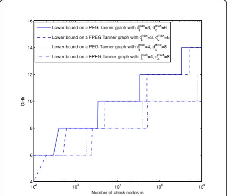
Figure 2 depicts the lower bounds on PEG Tanner graphs and the lower bounds on FPEG Tanner graphs for regular dmaxs = 3, dmaxc = 6 codes and dmaxs = 4, dmaxc = 8
codes with varyingmandR= 0.5. Note that due to the
flooring operation in (1) and (25), there are almost verti-cal transitions shown in Figure 2. A step size of 100 was used when varying the value ofm. It can be seen that, for the same dmaxs and dmaxc , the PEG Tanner graph and the FPEG Tanner graph have similar lower bound on girth. It can also be seen that for small values ofm, the girth can be 4. To avoid girth 4, equation below is used,
2
which can be simplified to
t= log(Jd
Hereafter in this article, for a givenm, it was assumed
M=dmax
s for two reasons: First, from (16) it can be
seen that the number of encoding steps is least when
M=dmax
s . Second, from (18) it is easy to see that J
grows linearly withrminand largerJvalue leads to larger
lower bound ongF. It is also easy to see that the
maxi-s . Therefore, the maximum
gFis achieved when M=dmaxs .
Note that there are degree-1 symbol nodes in the cor-responding FPEG Tanner graph and the fraction of degree-1 symbol nodes is r1/n. The existence of
degree-1 symbol nodes is a necessary condition for a linear-encoding algorithm such as the label-and-decide algo-rithm and the LPEG algoalgo-rithm [5,12]. However, it was stated that the outbound extrinsic messages of degree-1 nodes would not be updated during the iterative decod-ing process [16,17]. Consequently, the degree-1 symbol nodes would cause many problems such as mismatching of extrinsic information transfer (EXIT) functions and the halting of mutual information evolution. In the fol-lowing section, we will introduce a modified FPEG algo-rithm, which construct LDPC codes with only one degree-1 symbol node.
3.2 MFPEG algorithm
A simple modification of the FPEG algorithm can be applied to construct LDPC codes which have only one degree-1 symbol node. This modified algorithm is called
102
Number of check nodes m
Girth
Lower bound on a PEG Tanner graph with dsmax=3, d c max=6
Lower bound on a FPEG Tanner graph with ds max
Lower bound on a FPEG Tanner graph with dsmax=4, d c max=8
MFPEG algorithm in this article. The MFPEG algorithm is almost the same as the Algorithm 3 except for line 14. Therefore, we only describe the modified part in Algorithm 4.
Algorithm 4. MFPEG algorithm
1: Find out which check node groupGiincludesci. 2:if i= 1 (the first check node groupG1)then
SC←SC.
3:else
SC←SC\Gi.
4:end if
In a parity-check matrix corresponding to a Tanner
graph generated by the MFPEG algorithm, ther1 rows
of the submatrix H1 can have‘1’s in the same column.
Consequently,
{p1,p2,. . .,pr1}
should be computed serially, from pr1 to p1, in r1
steps by the parity-check equations inH1and the parity
bits
s are computed, in parallel, in one
step by the parity-check equations in Hi. Totally, the number of encoding steps of the MFPEG codes is
TM= (dmaxs −1) +r1
where the equality is achieved when r1 is the
mini-mum of {r1, r2, ..., rM}. In fact, the MFPEG algorithm has loosened the condition (A) and is a combination of the LPEG algorithm and the FPEG algorithm. Therefore, for a given degree distribution pair, we have the follow-ing equalities:
gF ≤gM≤gL, (32)
wheregM is the lower bound on girth of the MFPEG
Tanner graph.
Note that, since both of LPEG codes and MFPEG codes have only one degree-1 symbol node (FPEG codes
have r1 degree-1 symbol nodes), they may have the
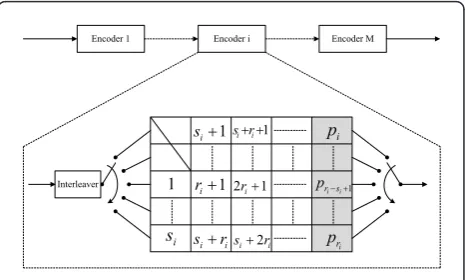
same symbol-node-degree distribution. As shown in Figure 3, the encoder of the proposed FPEG and
MFPEG codes can be implemented as ri SPC encoder
and one quasi-random interleaver, thus increasing com-plexity, compared to MPC encoder.
4 Examples and simulation results
In this section, we provide two examples of the pro-posed codes and compare them with the M-SC-MPC codes [10] and LPEG codes. In this article, we denote
LPEG codes, FPEG codes and MFPEG codes with M
submatrices by M-LPEG codes, M-FPEG codes, andM
-MFPEG codes respectively. In the first example it is shown that, In comparison to the M-SC-MPC codes which have the same number of encoding steps as FPEG codes, FPEG codes have better error correcting performance. In the second example, it is shown that for a given symbol-node-degree distribution, FPEG codes and MFPEG codes have similar error correcting performance but less encoding steps. In computing the error correcting performance, in terms of the bit error rate (BER), we assume BPSK transmission over the AWGN channel. The decoding algorithm used here is the log-likelihood sum-product algorithm and the maxi-mum iteration number is set to be 50.
Example 2: An M-SC-MPC code consists of M MPC encoders and offers a flexible code rate and code length with low encoding complexity [10]. The encoding
pro-cess of an M-SC-MPC code includesM steps, whereM
is also the maximum symbol-node degree, dmax
s . Clearly,
for the same maximum symbol-node degree, the num-ber of encoding steps of M-SC-MPC codes is the same as those of FPEG codes. Therefore, we will compare the performance of FPEG codes and M-SC-MPC codes, pro-vided that the number of encoding steps and the sym-bol-node-degree distributions are the same.
For the rate 3/4, in [10], the authors considered the following M-SC-MPC codes:
•4-SC-MPC: n = 1196,r1 = 59,r2= 73,r3 = 78,r4=
89;
•5-SC-MPC: n = 1268,r1 = 53,r2= 55,r3 = 59,r4=
67,r5 = 83;
Encoder 1 Encoder i Encoder M
1
•6-SC-MPC: n = 1204,r1 = 45,r2 = 46,r3 = 47,r4=
49,r5 = 53,r6 = 61.
The symbol-node degree distribution and check-node degree distributions of these codes from node perspec-tive are shown in Tables 1 and 2, respecperspec-tively. Using the same symbol-node-degree distribution, we construct the
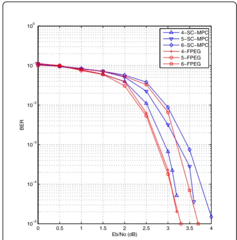
M-FPEG codes with the FPEG algorithm forM = 4, 5,
6. The BER performance comparisons of these codes are given in Figure 4. It is shown that anM-FPEG code per-forms better than that of the corresponding M-SC-MPC
code. At BER = 10-4, the advantage of the M-FPEG
codes against the M-SC-MPC codes are about 0.1, 0.7, and 0.3 dB, respectively, forM= 4, 5, 6.
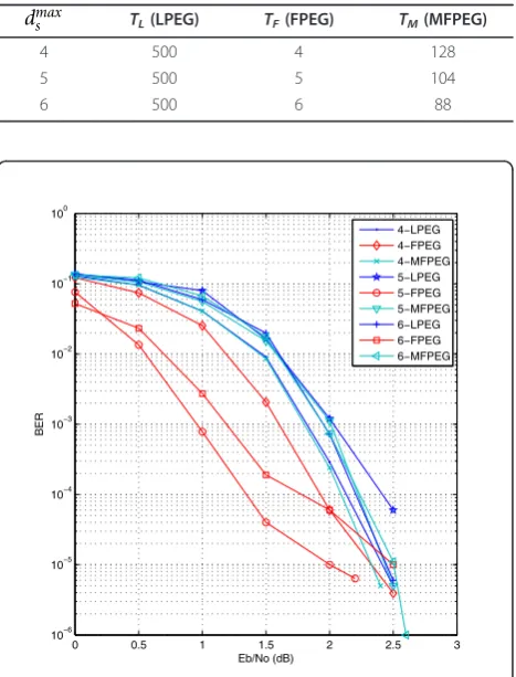
Example 3: We construct M-LPEG codes, M-FPEG
codes and M-MFPEG codes with the LPEG algorithm,
FPEG algorithm and MFPEG algorithm, respectively, for
M= 4, 5, 6, (dmaxs = 4, 5, 6). The code length is n =
1000, the parity-check length ism = 500 and the code
rate isR= 0.5. For the purpose of performance
compar-ison, the optimal degree distributions given in [[18], Table I] are used in this example. The fraction of Tan-ner graph edges which emanate from degree-1 symbol
nodes of M-LPEG codes, M-FPEG codes and M
-MFPEG codes can be obtained from that of the degree-i
symbol nodes by the following formula:
ψ∗
1 =ψi−ψi∗, (33)
whereψiis the original fraction of Tanner graph edges
which emanate from degree-i symbol nodes and ψi∗ is
the new fraction used in this example. Note that if the number of degree-2 symbol nodes of the Tanner graph
of His larger than or equal ton- m, any combination
of n- m degree-2 columns forms cycles. Thus we can
improve the error floor performance by reducing the fraction
λ2= ψ2 /2
jψj/j
, (34)
if the fraction of degree-2 symbol nodes is higher than the optimal value given in [19]. Therefore, for the origi-nal degree distributions ψi given in [[18], Table I], we obtained the degree-1 symbol nodes from the degree-2 symbol nodes by
ψ1∗ =ψ2−ψ2∗. (35)
The original node degree distributions are given in the Table 3 and in the simulation of this example, the degree distributions from edge perspective are given in Table 4.
Note that the symbol-node-degree distributions from node perspective for the LPEG, FPEG, and MFPEG algorithms can be calculated from edge distribution with the formula (7) and the check-node-degree distribution is not needed as the check-node degrees are made as uniform as possible by the LPEG algorithm [6] and the proposed FPEG and MFPEG algorithms. From (1) and (18), it is clear that the maximum check-node degree
dmax
c is necessary to derive the lower bound on girth.
However, the value dmax
c can be obtained easily in the
Table 1 Symbol-node-degree distributions of the M-SC-MPC codes
Code l1 l2 l3 l4 l5 l6
4-SC-MPC 0.0744 0.0652 0.0610 0.7993 5-SC-MPC 0.0655 0.0528 0.0465 0.0434 0.7918 6-SC-MPC 0.0510 0.0440 0.0410 0.0390 0.0382 0.7874
Table 2 Check-node-degree distributions of M-SC-MPC codes
Code r13 r14 r15 r16 r17 r18 r19 r20 r21 r22 r23
4-SC-MPC 0.1672 0.5618 0.0736 0.1572 0.0401
5-SC-MPC 0.1893 0.0726 0.0662 0.1640 0.4637 0.0442
6-SC-MPC 0.0532 0.1495 0.2757 0.4585 0.0631
0 0.5 1 1.5 2 2.5 3 3.5 4 10−5
10−4 10−3 10−2 10−1 100
Eb/No (dB)
BER
4−SC−MPC 5−SC−MPC 6−SC−MPC 4−FPEG 5−FPEG 6−FPEG
simulation program. The lower bound on girth, girth and average cycle length of the simulated codes are given in Table 5 and their number of encoding steps are given in Table 6. From Equations (5), (16), (31), and Table 6, it can be seen thatTF<TM<TLfor these given symbol-node degree distributions. The simulation results are shown in Figure 5. It is shown that, compared to the LPEG codes, the FPEG codes perform better in the waterfall region but worse in the error floor region. However, the MFPEG codes perform similarly to the LPEG codes.
5 Conclusion
In this article, we introduced the FPEG algorithm and the MFPEG algorithm for generating fast encodable LDPC codes. The number of encoding steps of the FPEG codes grows linearly withdmax
s , not the code lengthn. The
num-ber of encoding steps of the MFPEG codes grows linearly
with (dmax
s +
m dmax
s
−1). Moreover, we derived a lower
bound on girth of the FPEG codes which is shown to be similar to that of PEG codes. By examples and simulations, it is shown that compared to the M-SC-MPC codes the FPEG codes have the same number of encoding steps but better error correcting performance, and compared to the LPEG codes the FPEG codes have similar error correcting performance but less encoding steps. Variants of M-SC-MPC codes, in which the degree of freedom is exploited, have been proposed in [20,21]. Considering these variants of M-SC-MPC codes in the design of fast-encodable LDPC codes is an open issue for future research.
Acknowledgements
This study was supported by World Class University (R32-2008-000-20014-0) NRF, Korea. It was also supported partly by the National Nature Science Foundation of China (61104154), Specialized Research Fund for Natural Science Foundation of Shanghai (10ZR1401600) and Fundamental Research Funds for the Central Universities (11D10417).
Author details
1Donghua University, School of Information Science and Technology,
Shanghai, China2Donghua University, Engineering Research Center of Digitized Textile and Fashion Technology, Ministry of Education, Shanghai, Table 3 Original symbol-node-degree distribution in [18]
dmax
s ψ2 ψ3 ψ4 ψ5 ψ6
4 0.3835 0.0424 0.5741
5 0.3266 0.1196 0.1840 0.3699
6 0.3324 0.2463 0.1102 0.3111
Table 4 New symbol-node-degree distribution
Code ψ1∗ ψ2∗ ψ3 ψ4 ψ5 ψ6
4-LPEG 0.0010 0.3825 0.0424 0.5741 5-LPEG 0.0010 0.3455 0.1196 0.1840 0.3699 6-LPEG 0.0010 0.3314 0.2463 0.1102 0.3111 4-FPEG 0.1250 0.2585 0.0424 0.5741
5-FPEG 0.1000 0.2466 0.1196 0.1839 0.3699 6-FPEG 0.0830 0.2594 0.2463 0.1102 0.3111 4-MFPEG 0.0010 0.3825 0.0424 0.5741
5-MFPEG 0.0010 0.3455 0.1196 0.1840 0.3699 6-MFPEG 0.0010 0.3314 0.2463 0.1102 0.3111
Table 5 Girth lower bound, girth and average cycle length form= 500,n= 1000, andR= 0.5
Code dmax
c Girth Lower bound Average cycle length
4-LPEG 8 7 6 8.02
5-LPEG 6 8 6 7.99
6-LPEG 6 8 6 7.486
4-FPEG 6 7 6 7.49
5-FPEG 6 8 6 7.308
6-FPEG 6 8 6 7.126
4-MFPEG 6 7 6 8.142
5-MFPEG 6 8 6 7.876
6-MFPEG 6 8 6 7.532
Table 6 Number of encoding steps Form= 500,n= 1000, andR= 0.5
dmaxs TL(LPEG) TF(FPEG) TM(MFPEG)
4 500 4 128
5 500 5 104
6 500 6 88
0 0.5 1 1.5 2 2.5 3
10−6 10−5 10−4 10−3 10−2 10−1 100
Eb/No (dB)
BER
4−LPEG 4−FPEG 4−MFPEG 5−LPEG 5−FPEG 5−MFPEG 6−LPEG 6−FPEG 6−MFPEG
China3Chonbuk National University, Division of Electronics and Information
Engineering, Jeonju, Korea
Competing interests
The authors declare that they have no competing interests.
Received: 14 May 2011 Accepted: 21 May 2012 Published: 21 May 2012
References
1. RG Gallager, Low density parity check codes. IEEE Trans Inf Theory.IT-8(1), 21–28 (1962)
2. DJC MacKay, RM Neal, Near Shannon limit performance of low density parity check codes. IEE Electron Lett.32(18), 1645–1646 (1996). doi:10.1049/ el:19961141
3. J Feldman, MJ Wainwright, DR Karger, Using linear programming to decode binary linear codes. IEEE Trans Inf Theory.51(3), 954–972 (2005).
doi:10.1109/TIT.2004.842696
4. MH Taghavi N, PH Siegel, Adaptive methods for linear programming decoding. IEEE Trans Inf Theory.54(12), 5396–5410 (2008)
5. XY Hu, E Eleftheriou, DM Arnold, Progressive edge-growth Tanner graphs,
inIEEE Global Telecommunications Conf. (GLOBECOM), San Antonio, TX,2,
995–1001 (2010)
6. XY Hu, E Eleftheriou, DM Arnold, Regular and irregular progressive edge-growth Tanner graphs. IEEE Trans Inf Theory.51(1), 386–398 (2005) 7. X Jiang, MH Lee, Large girth quasi-cyclic LDPC codes based on the chinese
remainder theorem. IEEE Commun Lett.13(5), 342–344 (2009) 8. X Jiang, MH Lee, Large girth non-binary LDPC codes based on Euclidean
geometries and finite fields. IEEE Signal Process Lett.16(6), 521–524 (2009) 9. D Haley, A Grant, J Buetefuer, Iterative encoding of low-density parity-check
codes, inIEEE Globecom 2002, Taipei, Taiwan, Roc,2, 1289–1293 (2002) 10. M Baldi, G Cancellieri, A Carassai, F Chiaraluce, LDPC codes based on serially
concatenated multiple parity-check codes. IEEE Commun Lett.13(2), 142–144 (2009)
11. RM Tanner, A recursive approach to low complexity codes. IEEE Trans Inf Theory.IT-27(6), 533–547 (1981)
12. J Lu, JMF Moura, Linear time encoding of LDPC codes. IEEE Trans Inf Theory.56(1), 233–249 (2010)
13. X Jiang, MH Lee, Semi-random LDPC codes with efficient encoding. IEE Electron Lett.45(24), 1259–1260 (2009). doi:10.1049/el.2009.2314 14. JSK Tee, DP Taylor, PA Martin, Multiple serial and parallel concatenated
single parity-check codes. IEEE Trans Commun.51(10), 1666–1675 (2003). doi:10.1109/TCOMM.2003.818085
15. S Freundlich, D Burshtein, S Litsyn, Approximately lower triangular ensembles of LDPC codes with linear encoding complexity. IEEE Trans Inf Theory.53(4), 1484–1494 (2007)
16. G Yue, L Ping, X Wang, Generalized low-density parity-check codes based on Hadamard constraints. IEEE Trans Inf Theory.53(3), 1058–1079 (2007) 17. J Garcia-Frias, W Zhong, Approaching Shannon performance by iterative decoding of linear codes with low-density generator matrix. IEEE Commun Lett.7(6), 266–268 (2003)
18. T Richardson, MA Shokrollahi, R Urbanke, Design of capacityapproaching irregular low-density parity-check codes. IEEE Trans Inf Theory.47(2), 619–637 (2001). doi:10.1109/18.910578
19. W Weng, A Ramamoorthy, R Wesel, Lowering the error floors of irregular high-rate ldpc codes by graph conditioning, inVTC, Los Angeles, California,
4, 2549–2553 (2004)
20. M Baldi, G Cancellieri, F Chiaraluce, A De Amicis, Design of permuted serially concatenated multiple parity-check codes, inProc SoftCOM, Split, Croatia,1, 285–289 (2010)
21. M Baldi, G Cancellieri, F Chiaraluce, A De Amicis, Irregular M-SC-MPC codes for wireless applications, inProc 2010 European Wireless Conference, EW, Lucca, Italy,1, 369–376 (2010)
doi:10.1186/1687-1499-2012-178
Cite this article as:Jianget al.:Improved progressive edge-growth
algorithm for fast encodable LDPC codes.EURASIP Journal on Wireless
Communications and Networking20122012:178.
Submit your manuscript to a
journal and benefi t from:
7Convenient online submission
7Rigorous peer review
7Immediate publication on acceptance
7Open access: articles freely available online
7High visibility within the fi eld
7Retaining the copyright to your article