R E S E A R C H
Open Access
Multihop relaying and multiple antenna
techniques: performance trade-offs in cellular
systems
Kevin R Jacobson
1,2and Witold A Krzymie
ń
1,2*Abstract
Two very important and active areas of wireless research are multihop relaying and multiple antenna techniques. Wireless multihop relaying can increase the aggregate network data capacity and improve coverage of cellular systems by reducing path loss, mitigating shadowing, and enabling spatial reuse. In particular, multihop relaying can improve the throughput for mobiles suffering from poor signal to interference and noise ratio at the edge of a cell and reduce cell size to increase spectral efficiency. On the other hand, multiple antenna techniques can take advantage of scattering in the wireless channel to achieve higher capacity on individual links. Multiple antennas can provide impressive capacity gains, but the greatest gains occur in high scattering environments with high signal to interference and noise ratio, which are not typical characteristics of cellular systems. Emerging standards for fourth generation cellular systems include both multihop relaying and multiple antenna techniques, so it is necessary to study how these two work jointly in a realistic cellular system. In this paper, we look at the joint application of these two techniques in a cellular system and analyze the fundamental tradeoff between them. In order to obtain meaningful results, system performance is evaluated using realistic propagation models.
Keywords:MIMO transmission, Multiple antennas, Multihop relaying, Cross-layer design, 4G cellular networks, LTE-Advanced
I Introduction
The key goals for future broadband cellular systems are: reliable data transmission up to 1 Gb/s at high spectral efficiency, good coverage throughout the cells, and the ability to reliably serve a large number of mobile users. However, the wireless channel is a very difficult commu-nications channel over which to achieve reliable high speed data transmission. Due to numerous impairments, such as multipath propagation, random fading, high sig-nal losses, and interference, a strongly attenuated and corrupted signal appears at the receiver. In order to overcome this problem, wireless systems must use sophisticated transmission and receiver processing tech-niques in order to achieve satisfactory throughput at an acceptable error rate. Cellular systems are interference limited by design in order to maximize their capacity.
As a result, mobile users suffer from low signal to inter-ference and noise ratio (SINR), especially when they are at cell edges. This work considers two techniques that hold promise to further improve spectral efficiency of cellular systems while preserving their wide area cover-age: multihop (MH) relaying and multiple-input multi-ple-output (MIMO) antenna techniques.
MIMO transmission can improve capacity within a given bandwidth by taking advantage of the rich
scatter-ing in a typical wireless channel [1,2]. MIMO spatial
multiplexinguses uncorrelated spatial signatures of sig-nals at the receiver to create a number of spatial chan-nels to greatly increase capacity. This approach requires complex physical layer processing at the transmitter and/or receiver, and in order to approach potential capacity, full knowledge of the channel gains between all pairs of transmit and receive antennas. Under some cir-cumstances, channel state information must be known at both the transmit and receive ends. Multiple antennas also creatediversity that may be exploited to increase * Correspondence: [email protected]
1
Department of Electrical and Computer Engineering, University of Alberta, Edmonton, AB, T6G 2V4, Canada
Full list of author information is available at the end of the article
vides the greatest capacity gains at high SINR; however, cellular systems typically operate at low SINR, with users at cell edges suffering from the poorest SINR.
Multihop relaying [3-5], on the other hand, strives to mitigate transmission impairments by reducing the path loss between transmitter and receiver with the addition of intermediate wireless relays. With a short link hop, the path loss is greatly reduced, and obstacles can be avoided so that the SINR is increased and random signal fluctuations due to both shadowing and scattering are reduced. Higher link capacities and improved reliability can thus be obtained. With the higher SINR provided by multihop relaying, it is expected that MIMO techni-ques may perform better.
It has been observed that a cellular capacity wall of 350 Mb/s/cell [6] is on the horizon. Therefore, it is necessary to use smaller cells in order to achieve a higher spectral efficiency over an area (b/s/Hz/km2). One method of achieving this is to divide the larger cell, typically 1 to 2 kilometer in radius, into smaller subcells in which relay stations (RSs) serve mobile stations (MSs) closest to them. Numerous researchers have looked at the various approaches to MH relaying in cellular sys-tems [7-12]. Two proposals under consideration for 4G IMT-Advanced [13-15]: IEEE 802.16m [16,17] and LTE-Advanced [18,19] will include relaying as options. Clearly, relaying requires more complicated system level
algorithms (medium access control–MAC–layer and
higher) in order to achieve good results in a network of wireless stations. Also, MH relaying requires additional system resources (time or frequency slots), and hence the spectral efficiency (measured in b/s/Hz) may suffer under some conditions. It seems natural to combine MIMO and relaying techniques in order to improve the performance of a cellular system, but it is necessary to determine how well they work together and what trade-offs exist in combining them. In addition, it is necessary to use a system model that captures the radio frequency (RF) propagation of a typical cellular system accurately.
There exists a theoretical analysis of MH MIMO sys-tems [20]. However, some results in it have been derived under simplifying assumptions, and the complexity of a
hexagonal and Manhattan topologies.
Our work studies a cellular system combining decode and forward (DF) MH relaying with multiple antenna techniques with the goal of achieving higher data carry-ing capacity simultaneously with good system coverage. Much research has emerged recently on MH relaying and multiple antennas, which means there are a large number of considerations in the design of such a system. Our initial results in that area were presented in confer-ence papers [23,24]. This paper provides a more com-plete description of the system model used, additional more detailed results, their more extensive and much more insightful discussion and resulting conclusions, which may be of great value to cellular system designers.
The remainder of this paper is structured as follows: Section II provides details on the system model used for the MIMO link, a simple one-dimensional MH MIMO network and a two-dimensional cellular MH MIMO network. Section III gives calculated results for numer-ous scenarios. Section IV provides some detailed discus-sion of the results and Section V concludes the paper.
II System model
The MH model used in this paper is an extension of the single antenna MH relaying work in [25-27], in which typical cellular topologies and system parameters are used to calculate network throughput achievable using MH relaying. In the present paper, which presents and extends the research presented in [23,24], we include the benefits of multiple antenna techniques. The model is necessarily complex, taking into account both physical layer (PHY) and medium access control (MAC) layer considerations. A dual slope path loss model with dis-tance and other parameters typical of cellular systems is used. We capture both non-line of sight (NLOS) Ray-leigh and line of sight (LOS) Ricean aspects, which are selected as a function of distance.
A PHY layer model
1) MIMO Link
antennas andNRreceive antennas, and the channel is
described by an NR×NTmatrix H. Elements of Hare
modeled by a random variable that captures the stochas-tic nature of the wireless channel. We wish to model both line of sight (LOS) and non-line of sight (NLOS) conditions, and so, we express the channel matrix (nor-malized) as a sum of two components [28]:
H=
HNLOS is the NLOS (scattered) component, and its
elements are Rayleigh distributed with unity variance.
HLOSis the LOS (specular) component, and its elements
are deterministic. For our work, we assume that HNLOS
is full rank withrNLOS= min(NT, NR). HLOShas
maxi-mum rankrLOS= min(NT,NR) but for propagation
dis-tances and antenna array sizes typical of practical cellular systems, HLOS is rank-deficient and often has
rankrLOS= 1 [28,29]. Kr is the Rice factor: the ratio of
power in the specular component to the power in the scattered component. The capacity of a MIMO link is given by (Endnote A).
REP(H) = log2
where ris the signal to interference and noise ratio (SINR) at the receiver and INRis the identity matrix. SINR is determined by a number of system parameters, such as transmit power, antenna gains, receiver thermal noise, and path loss. The capacity is largest if both
HNLOS andHLOSare full rank, butHLOS is usually low
rank in practical systems. With low rankHLOSand high
Rice factor, a significant portion of energy will collapse into fewer eigenmodes of H, and thus, the capacity will be reduced. Monte Carlo simulation with a sufficiently large number of samples can be used to find the average capacity of the MIMO link. However, [29] gives very useful expressions for the upper bound on the average mutual information E[IH] of the Ricean MIMO channel.
Special case number 1 (Corollary 1) in [29] gives the upper bound for the average mutual information E[IH]
of a Ricean channel
R(H) = E[IH]≤log2[
metric function of T (see [29] and [30]). Special case number 2 (Corollary 2) in [29] is the case of a Ricean channel with rank 1HLOS
R(H) = E[IH]≤log2
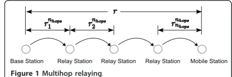
2)One-dimensional multihop relaying system
Consider the one-dimensional linear MH system shown in Figure 1, in which a base station (BS) wishes to trans-mit data to the mobile station (MS) at the cell edge via a number of relay stations (RSs). The cell radius, r, is divided intonhopshops, whose distances arernhops
k ,k= 1,
2, ..., nhops. To simplify calculations for the one-dimen-sional case only, we often use equally spaced relays so that rnhops
k =r/nhops, k= 1, 2, ..., nhops. In a MH MIMO
system, Figure 2, there arenhopschannel matrices,Hnhops
k ,
k = 1, 2, ...,nhops. Hopkhas NT,ktransmit antennas and NR,kreceive antennas.
For each hop,k, we have the channel matrix
Hnhops
averaged path gain and Rice factor for the kth hop,
respectively. The path loss model used is based on the Okumura-Hata and Walfish-Ikegami models for urban macrocell and microcell environments, as these are widely adopted by COST231, 3GPP [22], 802.16 [31] and other standards bodies. Since a benefit of MH relay-ing is the ability to relay around obstacles, we use a dual slope model, which selects non-line of site (NLOS) or line of sight (LOS) path loss as appropriate.g(x) is given by the path loss model (in dB, and extended to a fre-quency of 5 GHz [32])
PLdB(x) =−20log10[γ(x)] =
42.5 + 38.0log10(x) +ψdBb<x<5, 000 m,
38.2 + 26.0log10(x) +ψdB20 m<x<b (7)
wherex is distance, andb is the distance breakpoint, below which a NLOS path becomes LOS (typically 300 m in urban areas). A log-normal random variable, ψdB,
is optionally added in (7) to model random shadowing effects. ψdBhas zero mean, and its standard deviation, sψdB, is typically 10 dB in an urban NLOS microcell,
and 4 dB in an urban LOS microcell [22].
Similarly, the Rice factor,Kr(x), is modeled as a
func-tion of distance [22,33]
Kr(x) =
0 b<x<5, 000 m,
101.3−0.003x20 m<x<b (8)
From (7) and (8), we can see that the channel matrix elements are modeled as Rayleigh random variables when b < x <5, 000 m and Ricean (withKr >0) when
20m < x < b. This is a general and simple method of modeling the channel for the purposes of studying the interaction of MH relaying and MIMO in this paper. The precise RF propagation characteristics of a system will depend on the specific location, and a more accu-rate RF propagation simulation would be required. However, we believe that this simple model will enable sufficient insight into the system behaviour.
Capacity (normalized by bandwidth so that it is expressed in b/s/Hz), Rnhops
k of thekth hop is a function
R(·) (using (2), (3) or (5) as appropriate) of the channel realization for the hop:
Rnhops
k =R(H
nhops
k ),k= 1, 2,. . .,nhops (9)
When calculating the SINRs for the hops, interference from all other transmitting stations is included, at levels determined by their transmit powers, distances from the receiver, and antenna gains (see [25-27] for the detailed parameters). In MH relaying, interfering stations are usually far enough away that their signals experience the higher NLOS path loss.
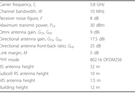
The primary system parameters used are summarized in Table 1.
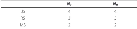
We have simulated cases, in which each hop uses (NT,
k×NR,k) = (1 × 1) (single antenna), (2 × 2), (3 × 3), (4
× 4), (5 × 5), and (6 × 6) MIMO. In practice, the BS can have a large antenna array, RSs must have a smaller array since they must be smaller and inexpensive, and MSs (laptop computers or mobile computing devices) are very limited in size. So we simulated a more realistic case (called the Mixedcase in the figures), as described in Table 2. This creates hops with (NT,k×NR,k) = (4 ×
3), (3 × 3), and (3 × 2) on the downlink BS-RS, RS-RS, and RS-MS hops, respectively. The uplink will have (NT,
k ×NR,k) = (2 × 3), (3 × 3), and (3 × 4) on the MS-RS,
RS-RS, and RS-BS hops, respectively. 3) Two-dimensional multihop cellular system
The one-dimensional model can be extended to two dimensions in order to simulate a two-dimensional cel-lular layout. A celcel-lular system is composed of numerous cells covering a large area. These cells are normally approximated as tessellating equal-size hexagons in most greenfield scenarios, or as equal-size squares in a downtown urban street scenario (Manhattan). A base station (BS) is deployed in the center of each cell and serves numerous mobile stations (MSs) in that cell. All frequency channels are reused in each cell (universal
Figure 2Decode and forward MH MIMO.
Table 1 Model parameters
Carrier frequency,fc 5.8 GHz
Channel bandwidth,W 10 MHz
Receiver noise figure,F 8 dB
Maximum transmit power,PTX 30 dBm
Omni antenna gain,GTX,GRX 9 dBi
Directional antenna gain,GTX,GRX 17.5 dBi
Directional antenna front-back ratio,GFB 25 dB
Link margin,M 5 dB
PHY mode 802.16 OFDM256
BS antenna height 32 m
Subcell RS antenna height 10 m
MS antenna height 1.5 m
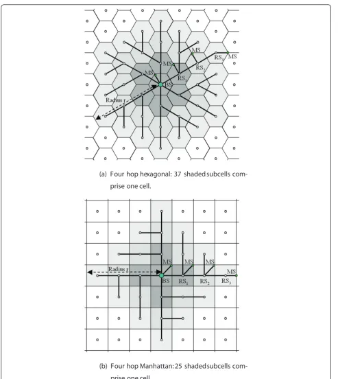
frequency reuse), which results in high co-channel inter-ference from one cell to another. This is mitigated by using MH relaying as shown in [27]. In an MH relaying cellular system, numerous relay stations (RSs) are deployed throughout the cell, which subdivides the cell into numerous subcells. A cellular system is best served using regularly-placed fixed relays (infrastructure-based relaying). Figure 3 shows examples of hexagonal and Manhattan topologies for the four-hop relaying case. In cellular systems, data connections occur between each MS and the BS, which creates bottlenecks on links toward the BS.
MSs will be served by the closest RS or BS, handing off as necessary to a closer station as the MS moves. As a result, some MSs will obtain service directly from the BS (one hop), some MSs will be served by RSs via two or more hops depending on their locations. MSs at the cell edge will be served via the maximum number of hops in the cell. Wirelesstransport links exist between the BS and its closest RSs, and between adjacent RSs, andaccess linksexist between a MS and its serving RS or BS. We consider only decode and forward relaying, in which the data stream is decoded and re-encoded at RSs before transmitting on the next hop. All relay sta-tions are wireless and may not transmit and receive simultaneously (half-duplex). We can calculate the signal to interference and noise ratio (SINR) at each station’s receiver and then find the rate attainable on each hop using a process similar to that described for the one-dimensional network.
B MAC layer
The previous section described the calculation of PHY layer capacities of each hop. But the key measure of per-formance of MH MIMO in a cellular system is the
over-all achievable network capacity, RNet. The MAC layer
coordinates transmissions as the data propagates from BS through RSs to the destination MSs, and so we must now consider network-wide scheduling of these trans-missions in order to determine network capacity.
As a first step, we consider non-spatial reuse schedul-ing, in which only one station in the entire macrocell is allowed to transmit in a channel at a particular time. This is not an efficient use of bandwidth, so we also consider spatial reuse in which simultaneous transmis-sions occur in the macrocell. In order to avoid inter-sta-tion interference and to ensure that a stainter-sta-tion is
guaranteed not to be transmitting at the same time it is receiving (Lane-man’s half-duplex constraint [34]), tions close to (one hop away from) a transmitting sta-tion must remain silent.
1) One-dimensional multihop relaying
It can be easily shown that for a linear MH system as shown in Figure 1, the non-spatial reuse network capa-city is
and the spatial reuse network capacity is
RNet,SR=
2) Two-dimensional multihop cellular system
RNet in a two-dimensional system can be calculated
knowing the data rates achievable on each of the links,
and by considering thespatial reuse schedule imposed
by the medium access control layer (MAC). With spatial reuse, data transmission can occur simultaneously in numerous subcells within the cell. The details of spatial reuse as applied to MH relaying have been presented in [27]. Expressions for RNethave been derived for up to four-hop hexagonal and Manhattan cellular topologies. These expressions are used to obtain the results pre-sented here.
III Results
A Single MIMO hop
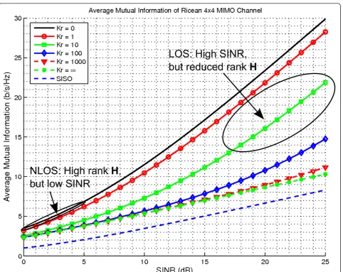
Here, we look at the performance of a single Ricean MIMO hop. As discussed earlier, the addition of relays shortens the hop distances, which reduces path loss and scattering (i.e., increases the Ricean factorKr). It is
use-ful to look at this effect on a single hop link before studying the full network. Figure 4 shows the average mutual information for a (4 × 4) MIMO link with full rankHNLOSand rank 1HLOScalculated from (5) [29].
Cellular systems generally operate at a fairly low SINR. It is easy to see from this figure that the rate advantage due to MIMO is relatively low at low SINR. We can increase the SINR on each hop by adding relays, but this may increase Kr, which reduces the MIMO capacity
gain, until at Kr=∞, there remains only 6 dB array gain
due to multiple receive antennas. From (8) we find that
Kr is still about 10 at a fairly short distance of 100 m,
and so MIMO gain, although reduced at this distance, is not completely lost.
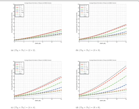
Figure 5 shows the dependence of capacity on the Rice factor and antenna configuration. More antennas do
Table 2 Mixed MH MIMO case
NT NR
BS 4 4
RS 3 3
provide higher capacities, but the loss in capacity with increasingKris greater.
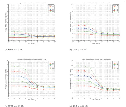
Figure 6 shows the dependence of capacity on the Rice factor and SINR. The plots show that the capacity can
drop off quite drastically with Kr at a fixed SINR,
espe-cially with a large number of antennas. Rice factor in cellular systems typically ranges from 3 to 20, which is in the range of steep reduction of capacity.
Figure 3Multihop relay cellular topologies.aFour hop hexagonal: 37 shaded subcells comprise one cell.bFour hop Manhattan: 25 shaded
The previous results show the effects ofKrand SINR with
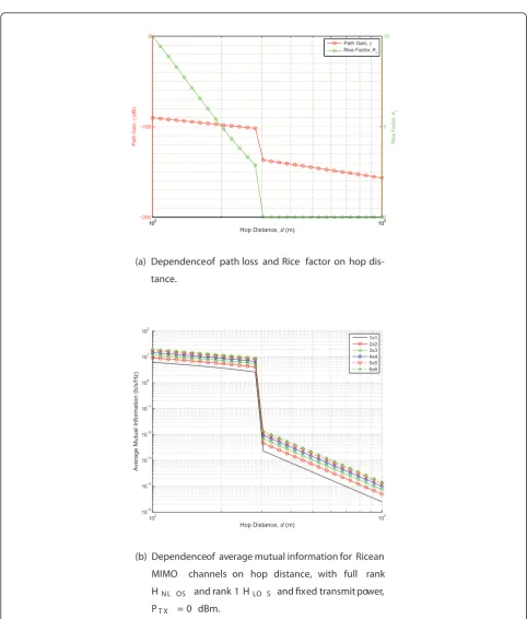
one of them fixed while we vary the other. However, Rice factor and path loss change simultaneously with distance in a real propagation environment, since a rich scattering environment (which is good for MIMO) also becomes depleted with decreasing LOS path loss. In the following figures, we examine the effects ofKrand SINR jointly using
theKr(x) andr(x) models given by (7) and (8). Figure 7a
shows howKrand path loss vary with distance, using a
dis-tance breakpoint of 300 m. Figure 7b shows the resulting hop capacity. It is clear that the loss in MIMO gain is small compared to the gain due to increased SINR.
B One-dimensional multihop relaying
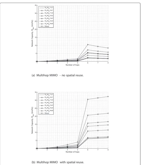
In this section, we look at how MIMO and MH relaying operate together in a one-dimensional linear system with co-channel interference. Numerous cases have been simu-lated using the system model as described. We include
here a sample of simulation results, for up to eight hops, and up to (6 × 6) MIMO. Figures 8 and 9 show some sam-ple results for a cell radius of 1,500 m, equally spaced relays and a distance breakpoint of 300 m. For fewer than six hops, all hops are NLOS and so the path loss of each hop is high. All hop paths are uncorrelated Rayleigh chan-nels, which should provide a good environment for capa-city gain due to MIMO spatial multiplexing. However, the hops suffer from low SINR due to high path loss and co-channel interference. Since spatial multiplexing works best at high SINR, MIMO capacity gain is minimal. With the addition of another relay (a sixth hop), all hops become LOS and the path loss of each hop becomes drastically reduced. As a result, the hop SINRs increase and the net-work capacity increases greatly. Although SINR is much higher, spatial multiplexing and diversity gains suffer due to the largely correlated propagation environment. How-ever, MIMO does assist in MH LOS situations because
Figure 4Upper bound on the average mutual information for (4 × 4) Ricean MIMO hop, with full rank HNLOSand rank 1 HLOS, and a
there remains some scattering component, and there exist receive array gain and interference control afforded by conventional transmit beamforming.
Figure 8 clearly shows the importance of spatial reuse in MH relaying. When there are more than two hops, channels (time or frequency slots) can be reused at sta-tions that are adequately separated in space, which pro-vides great increases in network-wide spectral efficiency despite the introduction of interference between subcells. Without spatial reuse, interference is lower, but MH relaying is more wasteful of spectrum. As shown in Fig-ure 8a, no spatial reuse case,RNet, decreases beyond 6 hops since relaying is increasingly wasteful of resources. With fewer than 6 hops, the addition of relays is slightly beneficial since the increase in SINR afforded by shorten-ing the hop distances increases the MIMO gain. In Figure 8b, with spatial reuse,RNetcontinuously increases with the number of hops. With more relays, there is more opportunity for channel reuse in distant parts of the cell.
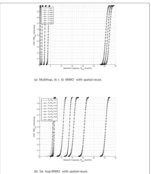
Cumulative distribution functions of MH MIMO net-work capacity for some cases are shown in Figure 9. The figure demonstrates the drastic capacity increase that MH relaying can achieve by avoiding NLOS propa-gation and enabling spatial reuse, and the gradual increase in capacity afforded by MIMO.
Figures 8 and 9 show the results using a rank one Hnhops
LOS,k, while Figures 10 and 11 show the results for full rankHnhops
LOS,k. The results are similar, but obviously RNet is higher when the LOS matrix is high rank (although this is not likely to occur in a real cellular system [29]).
C Two-dimensional multihop cellular system
In this section, we extend the calculations to a cellular system with tesselated Manhattan and hexagonal cells with one to four hops using the results of [27].
Universal frequency reuse is used among the cells for all cases. We assume the use of omnidirectional (in the SINR (dB)
Average Mutual Information (b/s/Hz)
Average Mutual Information of Ricean 4x4 MIMO Channel
Kr = 0
Average Mutual Information (b/s/Hz)
Average Mutual Information of Ricean 6x6 MIMO Channel
Kr = 0
Figure 5Upper bound on the average mutual information for a Ricean MIMO hop, with full rank HNLOSand rank 1 HLOS.a(NR×NT) =
horizontal plane) antenna elements for the MIMO arrays since they provide the greatest spatial spread.
For a detailed example, we show calculations for a hexagonal topology with circumscribed cell radius of 500 m. The hop distances for this case are given in Table 3. The resulting SINRs are given in Table 4.
It is useful to observe how distances, path losses, and SINRs change as relays are added to this system. The non-linear path loss model used, combined with the effect of scheduling transmissions among subcells within a cell, gives some non-linear and somewhat surprising results.
With no relays (n = 1), an MS at the cell edge is 500 m from the BS, which gives a NLOS channel according to the path loss model (7). In this case, reception at the MS suffers from high co-channel interference from
adjacent cells and a very poor SINR since we are consid-ering universal frequency reuse among cells. The
two-hop (n= 2) hexagonal case has six RSs around the BS
that gives two hops between the BS and any MS at the cell edge. The first hop, between the BS and any RS, is about 333 m and therefore is Rayleigh/NLOS according to the dual slope model. The second hop, between any RS and a cell-edge MS, is about 167 m and Ricean/LOS. The first-hop link suffers from high path loss, and experiences high co-channel interference from numer-ous RSs in other cells. In fact, there are three interfering RSs in other cells that are the same distance away as the BS. The interference is particularly bad from those RSs since the scheduling of RS transmissions in the other cells is not coordinated with the BS and RSs in the stu-died cell. Interference from within the stustu-died cell is 10−3
Rice Factor Kr
Average Mutual Information (b/s/Hz)
Average Mutual Information of Ricean MIMO Channel at 0dB
1x1
Rice Factor Kr
Average Mutual Information (b/s/Hz)
Average Mutual Information of Ricean MIMO Channel at 5dB
1x1
Rice Factor Kr
Average Mutual Information (b/s/Hz)
Average Mutual Information of Ricean MIMO Channel at 10dB
1x1
Rice Factor, Kr
Average Mutual Information (b/s/Hz)
Average Mutual Information of Ricean MIMO Channel at 20dB
1x1
Figure 6Upper bound on the average mutual information for a Ricean MIMO hop, with full rank HNLOSand rank 1 HLOS.aSINRr= 0
Figure 7Effect of hop distance, using dual slope model.aDependence of path loss and Rice factor on hop distance.bDependence of average mutual information for Ricean MIMO channels on hop distance, with full rankHNLOSand rank 1HLOSand fixed transmit power,PTX= 0
eliminated by scheduling. The second hop has a much better SINR since that link enjoys a much reduced path loss due to LOS, yet interfering signals are a greater dis-tance away and experience higher losses due to NLOS.
Adding 12 more RSs creates a three-hop hexagonal sys-tem. All three hops to an MS at the cell edge are LOS channels but the interfering channels are still NLOS. Also, RSs within the studied cell can be scheduled to minimize co-channel interference. Interfering RSs in other cells, uncoordinated with transmissions in the study cell, are now a much greater distance away and so have much less impact than in the two-hop case. The resulting improvement in SINR on the links is dramatic.
The next step, creating a four-hop hexagonal system, shortens the hops a little more. However, the incremen-tal improvement over three-hop is less dramatic since LOS links were already obtained by the three-hop sys-tem. Notice that the SINR has improved on the first hop fairly significantly since the inner RSs become more insulated from the interfering transmissions from other cells. The last hop does not improve much in SINR because it is still quite near interfering subcells in the adjacent cells.
With the SINRs calculated above, we can now calcu-late the rates on each hop, and the aggregate network rate, RNet, with spatial reuse. Single antenna, (3 × 3) MIMO, and mixed MIMO cases are shown in Tables 5, 6, and 7, respectively.
Figure 12 compares the aggregate bit rates achievable
by numerous MIMO configurations versus nhops, for
Manhattan and hexagonal topologies with 500 m radius cells. Figure 13 shows the results for 1,000 m radius cells.
IV Discussion
Results of this work show that there is a fundamental capacity tradeoff when using MIMO and MH relaying
jointly. This may seem obvious, since the two techni-ques actually work using conflicting assumptions: MIMO works by exploiting the randomly scattering channel, while MH relaying attempts to mitigate that random behaviour. A key effect is the loss of MIMO’s diversity and spatial multiplexing gains as relaying is introduced. This is apparent from (2) since, withrLOS=
1, the rank of Hdecreases and MIMO capacity gain is
lost as the Rice factor,Kr, increases. However, multiple
antennas provide advantages due to receive array gain, and due to minimization of co-channel interference with conventional transmit beamforming methods. Also, the use of MH relaying shortens the hop distances, which increases the SINR. So although scattering is reduced, SINR is increased. Increasing the SINR pro-vides higher spatial multiplexing gain, but reducing scat-tering reduces spatial multiplexing gain. To put this another way, MIMO’s spatial multiplexing and diversity gains are achieved at the expense of SINR: the uncorre-lated signal that is key to MIMO gains occurs because the signal experiences rich scattering associated with high path loss.
One might expect that MH relaying should work best since it addresses the real root of the problem–a weak
Table 3 Hop distances: 500 m radius hexagonal cell
Distance per hop (m) and path type (NLOS/LOS)
n r1 r2 r3 r4
1 500-NLOS - -
-2 333-NLOS 167-LOS -
-3 200-LOS 200-LOS 100-LOS
-4 143-LOS 143-LOS 143-LOS 71-LOS
Table 4 SINR: 500 m radius hexagonal cell
SINR per hop (dB)
n Hop 1 Hop 2 Hop 3 Hop 4
1 -5.4 - -
-2 -12.9 19.4 -
-3 28.9 19.8 17.4
-4 32.5 27.9 18.4 16.1
Table 5 Rates: 500 m radius hexagonal cell, single antenna
Table 6 Rates: 500 m radius hexagonal cell, (3 × 3) MIMO on each hop
received signal–while MIMO tries to make the best of a bad situation by collecting and making best use of ran-domly scattered signals. Consider the ultimate MH sys-tem, in which there are an infinite number of relays spaced at zero distance. The signal received at the end
destination at any distance from the sender would be perfect, but the cost of relay placement would be infi-nite, the delay long, and the algorithms and signaling overhead for routing prohibitively complicated. Hence, a sensible application of MIMO with MH relaying in a
mit side may reduce co-channel interference.
•Multiple antennas at the receiver will provide array gain.
V Conclusions
We have assembled a realistic model for MH MIMO in a cellular system. This model was used to determine the network capacity and investigate the tradeoffs associated with the combination of MH relaying and MIMO tech-niques. MIMO spatial multiplexing can provide great gains in capacity, but only when rich scattering occurs, as is the case when the channel is NLOS. Multihop relaying provides great advantage by relaying around obstacles, reducing the path loss by creating LOS condi-tions, and enabling spatial reuse of spectrum. We have shown that there is some tradeoff in using these meth-ods simultaneously, but by understanding the nature of this tradeoff in a typical cellular system, we can leverage the benefits of both MH relaying and MIMO. MH relay-ing can drastically increase SINR, but it still suffers from co-channel interference from neighboring uncoordinated cells. It is expected that network MIMO techniques, in which BSs in different cells coordinate their transmis-sions, may be used in conjunction with MH relaying. This is the subject of our current work.
Endnotes
Endnote A. We use equal power allocation in our work
in which all transmit antennas transmit with equal power. This is simpler and more realistic since knowl-edge of the channel at the transmitter is not needed. With such knowledge, the use of waterfilling on each hop can increase the hop rates, but this will not change any fundamental conclusions.
Acknowledgements
This work was supported by funding from the Natural Sciences and Engineering Research Council (NSERC) of Canada, TRLabs, Rohit Sharma Professorship, TELUS Communications, and Engineers Canada. The work was presented in part at the 10th International Symposium on Wireless Personal Multimedia Communications (WPMC07), Jaipur, India, 3 - 6 Dec 2007, and at GLOBECOM 2008, New Orleans, LA, USA, 30 Nov - 4 Dec 2008.
3. DC Schultz, B Walke, R Pabst, T Irnich, Fixed and planned relay based radio network deployment concepts, inProc 10th Wireless World Research Forum, (WWRF. New York, USA: The Institution of Electrical Engineers, October 2003). ISBN: 0-85296-753-5
4. T Irnich, DC Schultz, R Pabst, P Wienert, Capacity of a relaying infrastructure for broadband radio coverage of urban areas, inProc 10th WWRF meeting, New York, (Wireless World Research Forum (WWRF), 2003)
5. H Bolukbasi, H Yanikomeroglu, D Falconer, S Periyalwar, On the capacity of cellular fixed relay networks, inProc Canadian Conf on Elect and Comp Eng. 4, 2217–2220 (2004)
6. A Urie, The future of mobile networking will be small cells, inAlcatel-Lucent, Tech Rep, Presentation to IEEE IOFC Workshop, PIMRC’09, Tokyo, Japan (September 2009)
7. H Yanikomeroglu, Fixed and mobile relaying technologies for cellular networks, inProc Second Workshop on Applications and Services in Wireless Networks (ASWN’02), Paris, France, pp. 75–81 (July 2002)
8. R Schoenen, B Walke, On PHY and MAC performance of 3G-LTE in a multi-hop cellular environment, inProc WiCom, pp. 926–929 (September 2007) 9. O Oyman, NJ Laneman, S Sandhu, Multihop relaying for broadband wireless
mesh networks: From theory to practice. IEEE Commun Mag.45(11), 116–122 (2007)
10. SW Peters, R Heath Jr, The future of WiMAX: Multihop relaying with IEEE 802.16j. IEEE Commun Mag.47(1), 104–111 (2009)
11. SW Peters, AY Panah, KT Truong, RW Heath, Relay architectures for 3GPP LTE-Advanced. EURASIP J Wirel Commun Netw 1–14 (March 2009) 12. J Sydir, R Taori, An evolved cellular system architecture incorporating relay
stations–[WiMAX update]. IEEE Commun Mag.47(6), 115–121 (2009) 13. Requirements, evaluation criteria and submission templates for the
development of IMT-Advanced. ITU-R, Tech Rep, ITU-R M.2133 (2008) 14. Requirements related to technical performance for IMT-Advanced radio
interface(s). ITU-R, Tech Rep, ITU-R M.2134 (2008)
15. Guidelines for evaluation of radio interface technologies for IMT-Advanced. ITU-R, Tech Rep (2008). ITU-R M.2135
16. IEEE Standard for Local and Metropolitan Area Networks–Part 16. Air Interface for Broadband Wireless Access Systems, Amendment 1–Multiple Relay Specification(June 2009). IEEE Std. 802.16j-2009
17. IEEE 802.16m system description document. IEEE, Tech Rep, 802.16m-09/ 0034r2 (June 2009)
18. 3rd generation partnership project; technical specification group radio access network; feasibility study for further advancements for E-UTRA (LTE-Advanced) (release 9). 3GPP, Tech Rep, 3GPP TR 36.912 V9.0.0
(September 2009)
19. S Parkvall, E Dahlman, A Furuskar, Y Jading, M Olsson, S Wanstedt, K Zangi, LTE-Advanced–Evolving LTE towards IMT-Advanced, inProc VTC Fall, pp. 1–5 (September 2008)
20. H Bölcskei, RU Nabar, O Oyman, AJ Paulraj, Capacity scaling laws in MIMO relay networks. IEEE Trans Wireless Commun.5(6), 1433–1444 (June 2006) 21. IEEE Standard for Local and Metropolitan Area Networks–Part 16. Air Interface
for Broadband Wireless Access Systems(May 2009). IEEE Std. 802.16-2009 22. Universal mobile telecommunications system (UMTS); spatial channel model
for multiple input multiple output (MIMO) simulations. ETSI, Tech Rep (September 2003). 3GPP TR 25.996 Version 6.1.0 Release 6
24. K Jacobson, WA Krzymień, Multi-hop relaying and MIMO techniques in cellular systems–throughput achievable on Rayleigh/Ricean channels, in Proc Globecom, (New Orleans, Louisiana, November 2008)
25. K Jacobson, WA Krzymień, Realistic throughput of cellular multi-hop relay networks with spatial reuse, inProc WPMC-2006, (San Diego, USA, 2006), pp. 966–970
26. K Jacobson, WA Krzymień, Cell dimensioning and network throughput in cellular multi-hop relay networks, inProc VTC2006-Fall, (Montreal, Canada, September 2006)
27. K Jacobson, WA Krzymień, System design and throughput analysis for multi-hop relaying in cellular systems. IEEE Trans Veh Technol.58(8), 4514–4528 (2009)
28. A Paulraj, R Nabar, D Gore, inIntroduction to Space-Time Wireless Communications, (Cambridge, UK: Cambridge University Press, 2003) 29. J Salo, F Mikas, P Vainikainen, An upper bound on the ergodic mutual
information of Rician fading MIMO channels. IEEE Trans Wireless Commun. 5(6), 1415–1421 (2006)
30. RA Horn, CR Johnson, inMatrix analysis, (New York, NY, USA: Cambridge University Press, 1985)
31. V Erceg.,et al, Channel models for fixed wireless applications. IEEE, Tech Rep, IEEE-C802.16.3c-01/29r4 (July 2001)
32. DS Baum,et al, An interim channel model for beyond-3G systems: extending the 3GPP spatial channel model (SCM), inProc VTC2005-Spring, (Stockholm, Sweden, 2005), pp. 3132–3136
33. LJ Greenstein, S Ghassemzadeh, V Erceg, DG Michelson, Ricean K-factors in narrowband fixed wireless channels, inProc WPMC-1999(September 1999) 34. JN Laneman, GW Wornell, Distributed space-time-coded protocols for
exploiting cooperative diversity in wireless networks. IEEE Trans Inform Theory.49(10), 2415–2425 (2003). doi:10.1109/TIT.2003.817829
doi:10.1186/1687-1499-2011-65
Cite this article as:Jacobson and Krzymień:Multihop relaying and multiple antenna techniques: performance trade-offs in cellular systems. EURASIP Journal on Wireless Communications and Networking20112011:65.
Submit your manuscript to a
journal and benefi t from:
7Convenient online submission
7 Rigorous peer review
7Immediate publication on acceptance
7 Open access: articles freely available online
7High visibility within the fi eld
7 Retaining the copyright to your article