© 2015, IRJET.NET- All Rights Reserved
Page 736
Modular Robotic Arm
Santosh Chauhan
1, Swapnil Chaudhari
2, Ronak Sethiya
3, Sachin Ahire
4, Deepak Malche
51
Assistant Professor, Department of Mechanical Engineering, F.C.R.I.T, Vashi, Navi Mumbai – 400703, India.
2,3,4,5UG Students, Department of Mechanical Engineering, F.C.R.I.T, Vashi, Navi Mumbai – 400703, India.
---***---Abstract -
The flexibility and control of a robotic armhas been a challenge since earlier days of robots. K.H.Wurst developed the first Reconfigurable modular robots in the context of manipulator arms. P.K. Khosla developed a system which combines the flexibility of reconfigurable modular hardware with modular programming tools, allowing the users to rapidly create a manipulator which is custom-tailored for a given task. In the present paper, kinematic homogenous 4X4 matrix calculation is used to control the 3-axes modular robotic arm. With this approach it is possible to develop algorithms for controlling movements. Actual robotic arm has been designed using INVENTOR modelling software. Joints are moved using DC servo motors and the end effector is positioned using a pneumatic cylinder which is actuated using a solenoid valve with flow control valve to adjust the stroke speed. Arduino is used for controlling the robotic arm. The testing was carried out on a Jominy End Quench Apparatus and it was observed that the robot was working appropriately.
Key Words:
Modular robotic arm, Kinematic
modelling, Jominy End Quench Test
1. INTRODUCTION
Today’s industry’s focus is to minimize human intervention in handling critical environmental applications. With so much advancement and research works carried out across the world, this dream can be absolutely made into reality in the age of automation with the current technology. Pick and place robots are able to provide solutions in many applications.
Among the earlier work on this area, K.H.Wurst [1] developed the first Reconfigurable modular robots in the context of manipulator arms. He pointed out that, in the selection of robots in production environments, an optimal robotic device can seldom be reached and in most cases one has to make a compromise between selected robots and factors such as working range, speed, load and rigidity. P.K. Khosla[2] developed a system which
combines the flexibility of reconfigurable modular hardware with modular programming tools, allowing the users to rapidly create a manipulator which is custom-tailored for a given task. The central building block of a rapidly deployable system is a Reconfiguration Modular Manipulator System (RMMS). Y. Koga and J.C. Latombe [3] proposed a practical planner for PUMA arms manipulating an object using a predefined set of grasps. More recent work addressed a similar problem for the case of dual-arm manipulation with regrasping for a humanoid robot by N. Vahrenkamp [4].
In the present study, 3-DOF manipulator is designed and analyzed in order to gain an in depth understanding of positioning issues and solving with the use of kinematic modeling method. A 3-DOF modular robot is designed which uses 4x4 homogenous matrix to solve the position and orientation of end-effector from base. Position here, refers to position control in space of end-effector of robot arm of last link or base. The designed 3-DOF robot arm consists of 3 axes to generate arbitrary position in a specified space and last link is needed to handle the object. The end effector is positioned using a pneumatic cylinder which is actuated using a solenoid valve with flow control valve to adjust the stroke speed. This robotic arm is designed in INVENTOR software and MATLAB software is used for simulating the links. The fabrication is done by two high torque DC servo motors for joints moments and they are connected through the steel pipes. Arduino is used for controlling all DC servos.
The paper is organized as follows, in section 2 & 3, a brief description about kinematic analysis is given. In section 4, a brief discussion about design criteria of 3-dof robotic arm is given and Section 5, 6 & 7 represents simulation, testing and conclusion.
2. KINEMATIC ANALYSIS ALGORITHM
© 2015, IRJET.NET- All Rights Reserved
Page 737
position of geometric link parameters. It is used to find theposition and orientation of end effector. Inverse kinematics usually refers to position and orientation of end effector. It helps to find joint variables to archive correct position of source location part [6]. The relationship between direct and inverse kinematics problem is shown in Figure 1 with the help of simple block diagram.
Fig -1: Direct and Inverse kinematics problem [7]
3. INVERSE KINEMATIC ANALYSIS
The first step in the present study involved reviewing and understanding the configuration of a robotic arm. The details of forward and inverse kinematics for precise positioning of the end effector were studied. By using Denavit-Hartenberg (D-H) [5] inverse kinematics, the solution for the required configuration is obtained. The D-H parameters are shown in table 1.
Table -1: Parameters of Robotic Arm
i
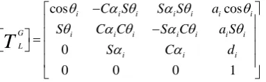
respect to that the other co-ordinate axes are set and from those co-ordinate axes the required parameter which describes the position and orientation of the end effector is obtained.General representation of the local co-ordinate axis with respect to global co-ordinate axis is as shown in equation (1) respect to that the other co-ordinate axes are set and from those co-ordinate axes we get the required parameter which describes the position and orientation of the end effector.
Transformation is given by the following matrix multiplication and generally represented as follow,
0
= elements of positional vector
© 2015, IRJET.NET- All Rights Reserved
Page 738
Comparing Matrix (3) with the general Matrix (2), we get
1 2 variables and geometric link parameters.
In order to control the position and orientation of end- effector of a robot arm to reach its object, the inverse kinematics solution is more important [7]. In this project, inverse kinematics problem is solved by geometric approach method. This method provides more insight into solving simple manipulators with rotatory joints [5].
4. DESIGN SPECIFICATIONS OF 3-DOF ROBOTIC
ARM
The presented mechanical design of robot consists of
2 links i.e., base, elbow. Gripper is connected at the
assemblies are connected to each other through steel
rods. This forms the whole assembly of a robotic arm
as shown in Figure 3.
Fig -2: Assembly of the motor block
Fig -3: Fully assembled robotic arm
© 2015, IRJET.NET- All Rights Reserved
Page 739
5. CONTROL SOFTWARE
The robotic arm is controlled using Matlab software. A GUI designed in Matlab computes the required angles of each joint using inverse kinematics. The computed values are sent to the Arduino MEGA 2560 microcontroller which then relay the information to the motors. The communication between Matlab and Arduino is done using serial protocol via USB. The different components of the Matlab GUI is shown in Figure 4.
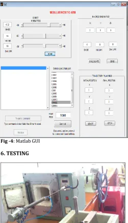
Fig -4: Matlab GUI
6. TESTING
Fig -5: Jominy End Quench Setup
The fabricated 3-DOF modular robot arm is introduced for real time handling of hot work piece in heat treatment operation (i.e., for Jominy End Quench test) and it controls the pick and place task during the testing. MATLAB interfacing with the robotic arm provides ease of operation in picking up the object.
7. CONCLUSIONS
In the present study, we have suggested a modular robotic arm which is easy to assemble and has low cost. This robotic arm that can be used in a collaborative environment working alongside human operator because of its light construction. The main objective of the project was to automate manual operation of object handling. This was achieved through the interfacing of robotic arm with MATLAB software. GUI is developed in MATLAB which calculates the link angles using inverse kinematics principle. Arduino MEGA 2560 is used which takes these link angles from GUI and actuates the motors.
The testing was carried out on a Jominy End Quench Apparatus and it was observed that the robot was working appropriately. The application of this robotic arm can be extended to pick and place any object whose weight is below 0.4 kg within a distance of 0.5 m from the base motor.
ACKNOWLEDGEMENT
We, the members of the group working on “MODULAR ROBOTIC ARM” would like to take this opportunity to thank all those who have whole heartedly lent their support and contributed in this project.
We are sincerely grateful to our HOD ‘Dr. S.M. Khot’ and principal ‘Dr. Rollin Fernandes’ for giving us an opportunity to work on this project.
We are sincerely thankful to our guide ‘Prof. Santosh J. Chauhan’ for his valuable, inspiring and timely guidance and assistance throughout the course of the project.
We would like to sincerely thank ‘Mr. Moreshwar Kor’, Instructor, Central Workshop, F.C.R.I.T Vashi for helping us with the fabrication of the components.
© 2015, IRJET.NET- All Rights Reserved
Page 740
REFERENCES
[1] K. H. Wurst, “The conception and construction of a modular robot system”, International Journal of Scientific and Research Publications, 1986.
[2] P. K. Khosla, H. B. Brosn, and C. J. Paredis, “A rapidly deployable manipulator system,” MN , pp. 1434–1439, 1996.
[3] Y. Koga and J.C. Latombe, “On multi-arm manipulation planning,” IEEE Conference on Robotics & Automation, volume 2, pp. 945–952, 1994.
[4] N. Vahrenkamp and et al., “Humanoid motion planning for dualarm manipulation and re-grasping tasks,” in IEEE/RSJ Int. Conf. on Intelligent Robots & Systems, October 2009.
[5] T. C. Manjunath, “Kinematic modeling and maneuvering of a 5-axes articulated robot arm,” World Academy of Science, Engineering and Technology 28 2007.
[6] Weihai and Guilin Yang, “Cartesian coordinate control for redundant modular robots,” IEEE Gintic institute of manufacturing technology, 2000.
[7] Min Tan., “An Analysis of the Inverse Kinematics for a 5-DOF Manipulator,” International Journal of Automation and Computing 2, China, 2005.
BIOGRAPHIES
Mr. Santosh J. Chauhan is a Assistant Professor in Mechanical Engineering Department of F.C.R.I.T. Vashi. He has eight years of experience and has published many research papers in national and international journals.
Mr. Swapnil S. Chaudhari is a Final Year Student in Mechanical Engineering Department of F.C.R.I.T. Vashi worked under this project.
Mr. Ronak Sethiya is a Final Year
Student in Mechanical
Engineering Department of F.C.R.I.T. Vashi worked under this project.
Mr. Sachin Ahire is a Final Year
Student in Mechanical
Engineering Department of F.C.R.I.T. Vashi worked under this project.
Mr. Deepak Malche is a Final Year
Student in Mechanical