Performance Analysis of Wind Generator Using Fuzzy Controller Fed
Back to Back Converter
P.Madasamy
1, N.Veerakumar
212Department of Electrical and Electronics Engineering,Alagappa Chettiar College of Engineering and Technology,
Karaikudi – 4, India
---***---Abstract -
The evolution of technology related to windsystems industry leaded to the development of a generation of variable speed wind turbines that present many advantages compared to the fixed speed wind turbines. These wind energy conversion systems are connected to the grid through Voltage Source Converters (VSC) to make variable speed operation possible. The studied system here is a variable speed wind generation system based on Doubly Fed Induction Generator (DFIG). The stator of the generator is directly connected to the grid while the rotor is connected through a back-to-back converter which is dimensioned to stand only a fraction of the generator rated power. To harness the wind power efficiently the most reliable system in the present era is grid connected doubly fed induction generator. The DFIG brings the advantage of utilizing the turns ratio of the machine, so the
converter does not need to be rated for the machine’s full
rated power. The rotor side converter (RSC) usually provides active and reactive power control of the machine while the grid-side converter (GSC) keeps the voltage of the DC-link constant. The additional freedom of reactive power generation by the GSC is usually not used due to the fact that it is more preferable to do so using the RSC. However, within the available current capacity the GSC can be controlled to participate in reactive power generation in steady state as well as during low voltage periods. The GSC can supply the required reactive current very quickly while the RSC passes the current through the machine resulting in a delay. Both converters can be temporarily overloaded, so the DFIG is able to provide a considerable contribution to grid voltage support during short circuit periods.
Key Words: DFIG-Double Fed Induction Generator WECS-Wind Energy Conversion System RSC- Rotor side Converter GSC-Grid Side Converter
1. INTRODUCTION
Wind Energy Conversion System (WECS) is the overall system for converting wind energy into useful mechanical energy that can be used to power an electrical generator for generating electricity. The wind power industry is growing. 2% of the world’s power production is wind energy and according to the “Global Wind Energy Council” wind power could meet 12% of the global power demand by 2020.a study of a DFIG wind power generation system for real-time simulations. For real-time simulations, the Real-Time Digital Simulator (RTDS) and its user friendly interface
simulation software RSCAD are used, The stator-flux oriented vector control scheme is applied to the stator/rotor side converter control, and the back-to-back PWM converters are implemented for the decoupled control. The real-wind speed signal extracted by an anemometer is used for a realistic, reliable and accurate simulation analysis. With increased penetration of wind power on power Systems, the influences of wind power penetration on an existing interconnected large power system dynamic behaviour, especially the transient stability analysis, must be considered carefully. Among the rest, Inter-area oscillations can be deteriorating the power system condition. These oscillations are as a result of the dynamics of inter-area power transfer in a large interconnected power network, which can seriously limit the system operation. To provide a safe operation for power system stability, damping of these oscillations have become one of the main problems [1-4].
The wind regime varies continuously and thus the system controllers should be updated to follow these variations. This paper is intended to apply fuzzy logic control techniques to overcome the effect of the wind speed variations on the parameters of the wind turbines and their controllers. The impact of the variation and uncertainty in the wind speed on the performance of the wind energy system is investigated in the paper. An adaptive fuzzy logic controller is proposed in this paper to cope with wind speed variations. the simulation and control of a grid connected doubly-fed induction generator driven by a variable speed wind turbine. Fuzzy logic control strategy is applied to doubly fed induction generator (DFIG). The MATLAB software is used to Simulate all the components of grid connected doubly fed induction generator (DFIG)-based wind power conversion system (WPCS). DFIG consists of a common wound rotor induction generator with slip ring and a back to back voltage source convertor. Fuzzy logic controller is applied to both grid side convertor (GSC) for dc link voltage control and rotor side convertor (RSC) for active and reactive power control [5-8].
dynamic response of DFIG based wind farm during and after the clearance of fault using the proposed fuzzy logic controller. The stability of wind farm during and after the clearance of fault is investigated. The effectiveness of the fuzzy logic controller is then compared with that of a PI controller. The validity of the controllers in restoring the wind farms normal operation after the clearance of fault is illustrated by the simulation results which are carried out using MATLAB/SIMULINK [9-10].
The paper has been organized as follows: Chapter II gives an overview of DFIG system. Chapter III describes the back to back converter modeling. Chapter IV explains the fuzzy controller. Chapter V explains the MATLAB simulation and its results. Finally, conclusion is presented in Chapter VI.
1.1 Doubly-fed Induction Machine
The most common machine which is widely used in these days is Doubly-fed Induction Machine. These types of machines can be used resolutely as a generator or motor. Though demand in the direction of motor is less because of its mechanical wear at the slip rings but they have gained their prominence for generator application in wind and water power plant because of its obvious adoptability capacity and nature of tractability.
.
1.2 Operating Principle
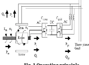
Fig. 1 shows the operating principle of DFIG system. The stator is directly connected to the AC mains, whilst the wound rotor is fed from the Power Electronics Converter via slip rings to allow DIFG to operate at a variety of speeds in response to changing wind speed. Indeed, the basic concept is to interpose a frequency converter between the variable frequency induction generator and fixed frequency grid. The DC capacitor linking stator- and rotor-side converters allows the storage of power from induction generator for further generation. To achieve full control of grid current, the DC-link voltage must be boosted to a level higher than the amplitude of grid line-to-line voltage. The slip power can flow in both directions, i.e. to the rotor from the supply and from supply to the rotor and hence the speed of the machine can be controlled from either rotor- or stator-side converter in both super and sub-synchronous speed ranges. As a result, the machine can be controlled as a generator or a motor in both super and sub-synchronous operating modes realizing four operating modes. Below the synchronous speed in the
motoring mode and above the synchronous speed in the generating mode, rotor-side converter operates as a rectifier and stator-side converter as an inverter, where slip power is returned to the stator. Below the synchronous speed in the generating mode and above the synchronous speed in the motoring mode, rotor-side converter operates as an inverter and stator rotor-side converter as a rectifier, where slip power is supplied to the rotor. At the synchronous speed, slip power is taken from supply to excite the rotor windings and in this case machine behaves as a synchronous machine.
Fig. 1 Operating principle
1.3 Vector Control
The overall control strategy of the machine is divided in two ways, one is scalar control and the other is vector control. The limitations of scalar control give an importance to vector control. Though the scalar control strategy is simple to implement but the inherent coupling effect gives sluggish response. The inherent problem is being solved by the vector control.
i. Transformation of three phase stationary to two phase stationary axes:
Consider a symmetrical three phase induction machine with stationary a-phase, b-phase and c-phase axes are placed at 120° angle to each other as shown in Fig.The main aim is to transform the three phase stationary frame variables into two phase stationary frame variables (ds-qs) and then transform these to synchronously rotating reference frame variables (d-q), and vice versa.
Let ds-qs axes are oriented at an angle θ from a -b-c axes as shown in Fig The voltage (vdss and vqss) can be resolved into a-b-c components and can be represented in the matrix form as
= (1)
The corresponding inverse relation is
(2)
Where v0ss is added as the zero sequence component. Other parameters like current, flux linkages can be transformed by similar manner. It is more convenient
to set θ=0°, so that q-axis is aligned with the a-axis in
this case (The alignment of the axes are optional, d-axis can also be aligned with a-axis). The sine components of d and q parameters will be replaced with cosine values, and vice versa if d-axis coincides with a-axis.
ii. Transformation of two phase stationary to two phase synchronously rotating axes:
The synchronously rotating d-q axes which rotate at synchronous speed ωe with respect to ds-qs axes. The two phase windings are transformed in to the fictitious windings mounted on the d-q axes.
The voltages on the ds-qs axes can be converted into d-q axes as follows;
= - (3)
= + (4)
iii. Modeling of DFIG in synchronously rotating frame
The equivalent circuit diagram of an induction machine is shown in this figure the machine is represented as two phase machine, it has already been discussed before that a three phase machine can be represent as two phase machine obeying certain rules. For the modelling of DFIG in synchronously rotating frame we need to represent the two phase stator (ds- qs) and rotor (dr-qr) circuit variables in a synchronously rotating (d-q) frame.
Fig. 3 Dynamic d-q equivalent circuit of DFIG (q-axis circuit).
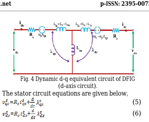
Fig. 4 Dynamic d-q equivalent circuit of DFIG (d-axis circuit).
The stator circuit equations are given below,
= + (5)
= + (6)
Converting Eqs to d-q frame the following equations can be written as
= + (ωe ) (7)
= + (ωe ) (8)
Where all the variables are in synchronously rotating frame. The bracketed terms are defined as the back e.m.f. or speed e.m.f or counter e.m.f. due to the rotation of axes as in the case of DC machines. When the angular speed ωe is zero the speed e.m.f due to d and q axis is zero and the equations changes to stationary form.
= + (ωe ) (9) = + (ωe )
(10)
Where all the parameters are referred to the primary circuit, which is stator in this case. Let the rotor rotates at an angular speed ωr, then the d-q axes fixed on the rotor fictitiously will move at a relative speed to the ω
e-ωr synchronously rotating frame.
= + (ωe (11)
= + (ωe (12)
The flux linkage expressions in terms of current can be written as
= + (13)
= + (14)
= + (15)
= + (16)
= + ) (17)
The torque expression can be written in terms of flux linkages and currents as follows
= ) (19)
The overall system is shown in Fig. 5. The basic components of the system are as follows.
1.DFIG (Wound rotor type Induction machine) 2.PWM Voltage source converters (Grid side converter and Machine side converter)
3.Utility grid 4.fuzzycontroller
Fig. 5 DFIG system
The modeling is carried out using MATLAB/ SIMULINK. The model uses flux linkages as the state variables as discussed above. Though the generator can generate in both sub and super synchronous mode, here the speed is taken as super synchronous speed, where the power can be extracted from the stator as well as rotor circuit. The machine uses two back to back converters in the rotor circuit. The main purpose of the machine-side converter is to controls the active and reactive power by controlling the d-q components of rotor current (i.e. idr and iqr), while the grid-side converter is to control the dc-link voltage and ensures the operation at unity power factor by making the reactive power drawn by the system from the utility grid to zero.
2. BACK TO BACK CONVERTER
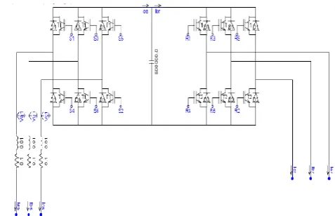
Two back to back voltage-fed current regulated converters are connected to the rotor circuit as shown in Fig. 6. The firing pulses are given to the devices (IGBTs) using PWM techniques. Two converters are linked to each other by means of DC-link capacitor. Realization of vector control principle for decoupling of generators active and reactive power , improvement of overall power factor, operation at synchronous speed by injecting dc current into the rotor, less distortion in currents are the functional characteristics of the back to back converters. Basically converter 1 controls the grid parameters where as the converter 2 serves for machine. As a duo both are responsible for overall control. The converters use six IGBTs (for three phase bridge type) as the controlled device for its obvious advantages. Each control device has an antiparallel diode, to permit active and reactive power flow in either direction.
2.1 Converter Control System
i. Rotor side converter control system
For the rotor-side controller the d-axis of the rotating reference frame used for d-q transformation is aligned with air-gap flux. The actual electrical output power, measured at the grid terminals of the wind turbine, is added to the total power losses (mechanical and electrical) and is compared with the reference power obtained from the tracking characteristic.
A Fuzzy regulator is used to reduce the power error to zero. The output of this regulator is the reference rotor current Iqr ref that must be injected in the rotor by converter C rotor. This is the current component that produces the electromagnetic torque Tem. The actual Iqr component is compared to Iqr ref and the error is reduced to zero by a current regulator (PI). The output of this current controller is the voltage Vqr generated by C rotor. The current regulator is assisted by feed forward terms which predict Vqr
C rotor. The reactive power is exchanged between C rotor and the grid, through the generator. In the exchange process the generator absorbs reactive power to supply its mutual and leakage inductances. The excess of reactive power is sent to the grid or to rotor.
ii.Grid side Converter control system
The Grid side converter is used to regulate the voltage of the DC bus capacitor. For the grid-side controller the d-axis of the rotating reference frame used for d-q transformation is aligned with the positive sequence of grid voltage. This controller consists of:
1. A measurement system measuring the d and q components of AC currents to be controlled as well as the DC voltage Vdc.
2. An outer regulation loop consisting of a DC voltage Regulator.
3. An inner current regulation loop consisting of a current Regulator.
The current regulator controls the magnitude and phase of the voltage generated by converter grid (Vgc) from the Idg_ref produced by the DC voltage regulator and specified Iq_ref reference. The current regulator is assisted by feed forward terms which predict the grid output voltage.
2.2 Pitch Angle Control System
The pitch angle is kept constant at zero degree until the speed reaches point D speed of the tracking characteristic. Beyond point D the pitch angle is proportional to the speed deviation from point D speed. For electromagnetic transients in power systems the pitch angle control is of less interest. The wind speed should be selected such that the rotational speed is less than the speed at point D.
Fig. 7 Pitch angle control system 3. FUZZY CONTROLLER
Fuzzy logic control has found many applications in the past decade. This is so largely because fuzzy logic control has the capability to control nonlinear, uncertain system even in the case where no mathematical model is available for the control system. The advantage of fuzzy logic controller is to provide an effective means of handling the approximate and inexact nature of the real world. The fuzzy logic also has features such as the resemblance to human thinking and the usage of natural language. With these features the fuzzy logic is applied to the control field, and the fuzzy logic has become a field of intelligent control and one of the emerging parts of research.
3.1 Fuzzy control system design
Fuzzy control provides a formal methodology for representing, manipulating, and implementing a human’s heuristic knowledge about how to control a system.
The fuzzy controller has four main components:
The “rule-base” holds the knowledge, in the form of a
set of rules, of how best to control the system, The inference mechanism evaluates which control rules are relevant at the current time and then decides what the input to the plant should be, The fuzzification interface simply modifies the inputs so that they can be interpreted and compared to the rules in the rule-base and The defuzzification interface converts the conclusions reached by the inference mechanism into the inputs to the plant.
Mean of maxima in this project we are using fuzzy controller for get constant charging current. For obtaining fuzzy controller in MATLAB, some procedure is to do in fuzzy interface system in MATLAB. We can use five primary graphical user interface tools for building, editing, and observing FIS in the toolbox.
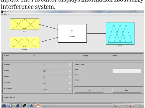
3.2 Fuzzy Inference System Editor
The FIS editor handles the high level issues for the system .Fuzzy tool box does not limit the number of inputs. The FIS editor displays information about fuzzy interference system.
The diagram shows names of the each input variable at the left, and those output variables on the right. The sample membership functions shown in the boxes are just icons and do not depict the actual shapes of the system. The FIS editor handles the high level issues for the system.
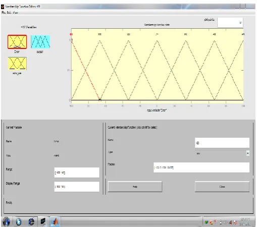
3.3 Membership Function editor
associated with each variable. Here error and error rate values is divided between -100 and 100 with seven variables. The name seven variables are Negative Small (NS), Negative Medium (NM) Negative Big (NB), Positive Small (PS), Positive Medium (PM), Positive Big (PB).Range can adjusted with suitable values.
Rule Table
Basically a linguistic controller contains rules in the If-then format. Here used seven variables for one input, then totally 49 rules.
Table -1: RULE TABLE
3.4 Rule editor
The Rule Editor is for editing the list of rules that defines the behavior of the system. Rule base consist of If –then rules which tie the inputs with the outputs. Using if –then rules, stored in the rule base, convert
fuzzy inputs to fuzzy output. Here we are using two parameters error and error rate, which is scaled Negative Small (NS), Negative Medium(NM) , Negative Big(NB), Positive Small(PS), Positive Medium(PM), Positive Big(PB). Depending these variables we are creating or editing rule editor.
4. SIMULATION
In this section the performance of the DFIG system is analyzed under grid voltage fluctuations. The voltage fluctuations are made by lowering and raising the voltage values in the utility grid intentionally for the purpose of simulation keeping in view of different grid disturbances. The effect of change in wind speed and change in supply frequency are also taken into consideration for the performance analysis of DFIG. The analysis is also done by changing the demand of reactive power of machine. The performance analysis is done using simulated results which are found using MATLAB and also the results are validated using Real Time Distributed Simulation package.
The simulation diagram for overall system, wind turbine, fuzzy controller is shown from Fig. 11 to Fig. 13.
Fig. 11 Overall Simulation circuit ERROR
RATE ERROR
NB NM NS ZE PS PM PB
NB ZE PS PS PM PM PB PB
NM NS ZE PS PS PM PM PB
NS NS NS ZE PS PS PM PM
ZE NM NS NS ZE PS PS PM
PS NM NM NS NS ZE PS PS
PM NB NM NM NS NS ZE PS
Fig. 12 Simulation diagram of Wind turbine
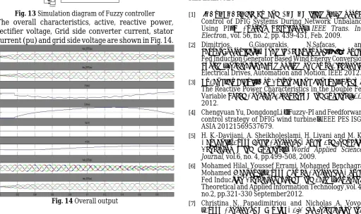
Fig. 13 Simulation diagram of Fuzzy controller The overall characteristics, active, reactive power, rectifier voltage, Grid side converter current, stator current (pu) and grid side voltage are shown in Fig. 14.
Fig. 14 Overall output
Fig. 15 Grid Voltage
5. Conclusion
Control and operation of a DFIG-based wind power generation system under unbalanced supply voltage conditions have been investigated in this thesis. A new coordinated control strategy for the RSC and GSC has been proposed. The RSC is controlled to eliminate the electromagnetic torque oscillation while the GSC compensates for the oscillation of the DFIG stator output active power to eliminate the oscillation in the total active power generated from the overall system. Fuzzy-logic controller is used as according to user defined rules. This paper presents a study of Fuzzy Logic Controller in a DFIG system. Simulation results prove that Fuzzy Logic Controller gives improved performance. Fuzzy Logic Controller exhibits the best steady-state accuracy and robustness to parameters variations, but its implementation is complicated. With fuzzy controller the power quality and voltage stability are improved.
REFERENCES
[1] J. Hu, Y. He, Lie Xu and B. W. Williams, “Improved
Control of DFIG Systems During Network Unbalance Using PI–R Current Regulators” IEEE Trans. Ind. Electron., vol. 56, no. 2, pp. 439-451, Feb. 2009.
[2] Dimitrios, G.Giaourakis, N.Safacas, and
SavvasTsotoulidis, “Dynamic Behaviour of 1.5 M Doubly -Fed Induction Generator Based Wind Energy Conversion System” International Symposium on Power Electronics, Electrical Drives, Automation and Motion, IEEE 2012.
[3] YuFang,Liu Qihui1,Hou Guixin Zhang Jianhua, “Study of
The Reactive Power Characteristics in the Double Fed Variable Speed Constant Frequency Wind Turbine” IEEE 2012.
[4] Chengyuan Yu, DongdongLi , “Fuzzy-PI and Feedforward
control strategy of DFIG wind turbine” IEEE PES ISGT ASIA 20121569537679.
[5] H. Davijani, A. Sheikholeslami, H. Livani and M.
K.-Davijani, “ Fuzzy Logic Control of Doubly Fed Induction Generator Wind Turbine,” World Applied Sciences Journal, vol.6, no. 4, pp.499-508, 2009.
[6] Mohamed Hilal, Youssef Errami, Mohamed Benchagra,
Mohamed Maaroufi, “Fuzzy Power Control for Doubly Fed Induction Generator based Wind Farm” Journal of Theoretical and Applied Information Technology ,vol. 43 no.2, pp.321-330 September2012.
[7] Christina N. Papadimitriou and Nicholas A. Vovos,
Micro-grids” Fundamental and Advanced Topics in Wind Power, ISBN 978-953-307-508-2, June 2011.
[8] B. Babypriya, N. Devarajan, “Simulation and Analysis of a
DFIG Wind Energy Conversion System with Genetic Fuzzy Controller” International Journal of Soft Computing and Engineering (IJSCE) ISSN: 2231-2307, Volume-2, Issue-2, May 2012.
[9] FuratAbdalRassul Abbas and Mohammed Abdulla
Abdulsada, “Simulation of Wind-Turbine Speed Control by MATLAB” International Journal of Computer and Electrical Engineering, vol. 2, No. 5, October, 2010.
[10] ArashAbedi, MojtabaPishvaei, Ali Madadi and