R E S E A R C H
Open Access
A robust generalized sidelobe canceller via
steering vector estimation
Xu Wang
*, Julan Xie, Zishu He and Huiyong Li
Abstract
In the presence of the direction of arrival (DOA) mismatch, the performance of generalized sidelobe canceller (GSC) may suffer severe degradation due to the gain loss of the desired signal in the main array and cancellation. In this paper, one effective GSC algorithm is proposed to improve the robustness against the DOA mismatch of the desired signal. Firstly, two subspaces, which contain the desired signal’s actual steering vectors of the main and auxiliary arrays, can be obtained by using the range information of the angle which the desired signal may come from. By rotating these two subspaces, the desired signal’s actual steering vectors of the main and auxiliary arrays can be estimated based on the maximum output power criterion. Then, with the estimates of the steering vectors in the former step, the gain loss of the desired signal in the main array can be alleviated. Moreover, one adaptive weight vector with the ability to block the desired signal in the auxiliary array can be obtained simultaneously, which effectively avoids the signal of interest cancellation consequently. Cycle iterative approach is also applied to guarantee the estimation accuracy of a wide range of angle deviation. Numerical simulations demonstrate the effectiveness and applicability of the proposed method.
Keywords:The generalized sidelobe canceller (GSC), DOA mismatch, Output power maximization, Steering vector estimation
1 Introduction
The adaptive antenna has the ability to select a set of amplitude and phase weights with which to combine the outputs from the elements to consequently produce an artificially controlled beampatttern that optimizes the re-ception of a desired signal. This form of array processing provides relevant improvements in anti-interference per-formance which has been widely applied in numerous fields, such as military radar, communication, medical imaging, and navigation in decades [1–6]. A large scale of adaptive array is commonly utilized to obtain better resolution and interference cancellation performance, which results to the consequence that the computational load becomes the bottleneck in the implementation of an adaptive beamforming algorithm. To save computational cost, the generalized sidelobe canceller (GSC) is an effective approach generally applied in radar and communication systems where the desired signal is only presented in a fraction of time or the amplitude of the desired signal
in the auxiliary array is generally very small [7, 8]. The GSC can work as an adaptive beamformer that usually improves the gain of the desired signal by forming a mainlobe toward the direction of arrival (DOA) of the desired signal and in the meanwhile suppresses the in-terferences by nulling at the DOAs of the interference signals. However, the low implementation complexity makes the GSC more popular than the common adap-tive beamformer in the practical application [9–11]. It is well known that, in the presence of the desired signal existing in the observation data received by the auxiliary array, the GSC inclines to misread the desired signal as interference and to cause a signal of interest (SOI) cancellation consequently [12]. The blocking process is one commonly applied technique to avoid the SOI cancellation which blocks the desired components from the primary data of the auxiliary array before the adaptive cancelling. As long as the desired signal is effectively blocked from enter-ing the interference cancellenter-ing filter, only interference cancellation occurs, thus giving a higher overall output SNR than with conventional beamforming alone. However, this approach is very sensitive to the mismatch of the * Correspondence:[email protected]
University of Electronic Science and Technology of China, 611731 Chengdu, Sichuan, China
desired signal’s direction of arrival that can boil down to the mismatch of the steering vector of interest (SVI). Add-itionally, the uncertainty of SVI will induce the gain loss of the desired signal in the main array which brings about the dramatic degradation of the output signal-to-interference and noise ratio (SINR).
In these years, improving the robustness of the beam-former against the mismatch of the steering vector is becoming an essential requirement and several contri-butions have been proposed to work on it [13–19]. Against the DOA mismatch, the most common tech-nique is to delimit one set of unity-gain constraints for a small range of angles around the presumed look dir-ection. Nevertheless, this technique critically sacrifices the degrees of the auxiliary array freedom and may de-grade the anti-interference performance. Consequently, how to precisely estimate the actual steering vector has attracted considerable attention. In [20], the joint max-imum likelihood (ML) estimators of the useful signal and interference vectors were derived and the estima-tion problem was casted as a semidefinite program (SDP) problem. In [21], the ML estimator was still ap-plied which led the steering vector estimation problem into a fractional quadratically constrained quadratic problem (QCQP). Nevertheless, this method cannot be straightforwardly applied in the GSC structure. In [22], the maximum output power criterion was introduced. To-gether with several novel constraints which prevented the estimation converging to the interference subspace, the de-sired signal’s actual steering vector was obtained by solving the QCQP. However, the high computational burden prevents it from practical usage. Furthermore, analytical solution cannot be obtained. In [23], the constraints to avoid the angle ambiguity were replaced by the subspace projection. Ultimately, either the analytical solution or the low calculation complexity was realized. This work made a great motivation for the method proposed in this paper.
In our previous work [24], only SOI cancellation has been worked out. However, the gain loss of the main array may still cause the output SINR deterioration in the case of the DOA mismatch. Hence, this paper is mainly con-cerned with two basic issues caused by the desired signal’s DOA mismatch: the SOI cancellation and the gain loss of the desired signal in the main array. Firstly, one angular sector expressed asΘ¼θ′0−Δθ;θ′0þΔθhas to be prop-erly selected from which the desired signal may come. θ′0 denotes the assumed DOA of the desired signal. This sector can be either obtained from the priori knowledge or the low accuracy angle measurement. Hence, two sub-spaces constructed from the steering vectors of DOAs withinΘover the main and auxiliary arrays can be ob-tained. It has been proved [23] that both SVIs (the main and auxiliary arrays) can be expressed as linear com-binations of the basis vectors of these two subspaces,
respectively. By utilizing the successive maximization of the array output power while limiting the SVIs within the according subspaces, we can iteratively obtain the estimations of the actual SVIs. Ultimately, the optimum weights of the auxiliary and main arrays can be worked out thereafter.
The remainder of this paper is organized as follows. In Section 2, the fundamental theory of GSC and the prob-lem discussed in this paper are reviewed. In Section 3, one novel robust GSC is proposed. In Section 4, the computational complexity is analyzed. Simulation results are shown in Section 5, while the last section gives some concluding remarks.
2 Background
Considering the full investigation of the GSC, we briefly recall it as a review. Without loss of generality, the typical structure of the GSC with the auxiliary array separated from the main array is considered. Nevertheless, the algo-rithm proposed is still suitable for the collocated scenario. Both the main array and the auxiliary one are considered to be uniform linear arrays comprised of Nm and Na
omnidirectional elements with inter-element spacing d, respectively. Hence, the basic output of GSC is given as
e tð Þ ¼wHmxmð Þt −waHB θ′0 xað Þt ð1Þ
where wm∈ℂNm1 denotes the quiescent weights of the main array commonly pointing to the desired signal’s DOA. wa is the adaptive complex weight vector of the
auxiliary array that is usually obtained based on the cri-terion of minimization of the array output power. xm(t)
andxa(t) are the complex vectors of the main and
auxil-iary array observations which are written, respectively, as
xmð Þ ¼t am;0ð Þθ0 s0ð Þ þt
envelops of the desired signal and the interferences and am,i(θi) and aa,i(θi) denote the steering vectors
corre-sponding to the ith signal in two antenna arrays. nm(t)
and na(t) are the additive noise vectors whose
compo-nents are considered to be spatially and temporally Gaussian processes. B θ′0 ∈ℂNaðNa−1Þ refers to the blocking matrix relying on the assumed DOA of the de-sired signal which has the property denoted asB θ′0 aa;0 θ′0 ¼0 . θ0 is the desired signal’s DOA. Based on the
introduced to the auxiliary array before the adaptive inter-ference cancelling. Hence, the optimum complex weights of the auxiliary array can be easily carried out by minimiz-ing the residue output power‖e(t)‖2and given as follows practice, they are usually substituted by the sample
covariance matrices R^a ¼1=L
mð Þl withLtraining snapshots. As the above content mentioned, the blocking matrix is applied to preprocess the data received by the auxil-iary array to exclude the desired signal components. Under ideal circumstances (i.e., no mismatch exists and θ′
0¼θ0), the SOI cancellation can be effectively avoided through the blocking procedure. The residue output can be expressed as follows
However, the performance of the blocking procedure highly relies upon the accuracy of the desired signal’s DOA. Once there exists a mismatch between the presumed desired signal’s DOA and the actual one (i.e., θ′0≠θ0), two major issues may be induced to the GSC system: (i) the blocking process can not sufficiently eliminate the desired signal received by the auxiliary array, which will lead to the SVI cancellation (i.e., B θ′0 aa;0ð Þθ0 ≠0 ) and (ii) the entire gain of the desired signal in the main array will decrease as a result of the main beam pointing deviation (i.e., by this time,wHmam;0ð Þθ0 <jwHmam;0 θ′0 j). Consequently, the ul-timate output SINR of the GSC will significantly deteriorate on the account of these two issues. Therefore, it is of great importance to avoid the SVI cancellation and alleviate the gain loss of the desired signal in the main array simultaneously.
3 Proposed robust algorithm
In this section, one iterative robust GSC algorithm will be presented. According to the fundamental theory of GSC, it can be seen that the blocking process is equiva-lent to force the auxiliary array output of the desired signal to be zero. Therefore, the basic operation can be cast as an optimization problem which is expressed as follows
With the additional constraint, the desired signal can keep off cancelling. By utilizing the Lagrange multiplier method, the solution can be easily obtained and expressed as follows
By substituting (7) into the objective function of (6), the residue output power of GSC can be written as
ΔP¼wH
Therefore, by regarding the steering vector aa;0 θ′0 as a variable, the actual steering vector aa,0(θ0) may have
possibility to be estimated by maximizing the array out-put power under the assumption of great capability in anti-interference performance. Hence, a new optimization problem to estimate the actual steering vector can be built and given as follows
The optimization problem of (10) can become a typical generalized eigenvalue problem. Hence, the analytical so-lution can be straightforwardly carried out [25]. This method is called generalize eigenvector GSC (GE-GSC). However, it is highly possible to converge the estimation of the actual steering vector to the interference subspace that will lead to the anti-interference performance degrad-ation. To avoid this phenomenon properly, constraints are imposed in [15] while the solution is finally obtained using sequential quadratic programming (QP) iteratively. Nevertheless, this method cannot lead to a closed form solution, and the high computational cost prevents it from implementation.
angular sector expressed as Θ¼θ′0−Δθ;θ′0þΔθ with-out any exception, where Δθ denotes the DOA uncer-tainty range. This angular sector is usually easy to obtain in practice. Therefore, by integrating the steering vector correlation, we can build a positive definite matrix given as follows
Pa¼ Z
Θ
sað Þθ sHað Þθ dθ ð11Þ
where sa(θ) is the steering vector of the signal source
impinging on the auxiliary array from direction θ. After eigenvalue decomposition, we can get
Pa¼U1Λ1UH1 þU2Λ2UH2 ð12Þ
whereΛ1is the diagonal matrix with its diagonal elements
given byK1-dominant eigenvalues.U1is the column
or-thogonal matrix consisting of the corresponding eigen-vectors. It has been proved by [22, 23] that the actual steering vector of the desired signal definitely locates in the subspace expanded by the column ofU1. By rotating
this subspace with unsolved coefficient vectorv, the steer-ing vector ambiguity can be avoided. Hence, the additional constraint can be simply given as aa,0(θ) =U1v.
Conse-quently, by substituting it into (10), we can translate the estimation of the steering vector into estimating the rotat-ing coefficient. Then, the modified optimization can be given as
a U1. To solve the optimum solution of (13), we release the constraint which can be straightforwardly satisfied by normalization method. Firstly, one new variable is re-quired to be defined as v~¼M1=22 v, where M1=22 denotes the square root of the M2. Substituting v¼M−1=22 ~v into the objective function of (13), we can get
max
Consequently, one typical Rayleigh quotient problem is given, and the solution can be written as the eigenvector
of M−1=22
H
M1 M−1=22
corresponding to the maximal
eigenvalue [25]. Then, the characteristic equation can be expressed as
whereλmaxis the largest eigenvalue andṽ* the eigenvector
correspondingly. Based on the eigenvalue decomposition
expressed asM2¼
Hence, M−1=22 is the Hermitian matrix with the
prop-erty of M−1=22 ¼M−1=22 H. By multiplying the left side
of the characteristic equation byM−1=22 , we can get
M−1 tion of problem (13) can be given by
^
v¼Eig M−21M1
ð18Þ
where Eig[•] is the operator that yields the eigenvector corresponding to the largest eigenvalue. In order to sat-isfy the norm constraint of (13), normalization is ap-plied. Ultimately, the estimate of the auxiliary steering vector can be written as
^
It is worth mentioning that the operation above needs to set the initial value of the complex weights as wm=
wpre, where wpre is the initial quiescent weights of the
main array constructed based on the presumed DOA of the desired signal. By substituting (19) into (7) and util-izing the initial quiescent weights wpre, the adaptive
weights of the auxiliary array can be obtained which may achieve the goal to eliminate the SVI cancellation. However, the beampattern of the main array still points to the incorrect direction of the desired signal. As the above content mentioned, it will lead to the gain loss in the main array. Henceforth, we turn our attention to solve this problem.
Based on the principle that the matched filtering weights of the spatial domain are equal to the steering vector of the desired signal over the main array, we can update the initial complex weightswmwith the estimate
of am,0(θ0). Similarly, one positive matrix needs to be
Pm¼ Z
Θ
smð Þθ sHmð Þθ dθ ð20Þ
where sm(θ) is the steering vector of the main array
lo-cated in direction θ. Likewise, one column orthogonal matrix U′1 can be built from the principal eigenvectors corresponding to the K2-dominant eigenvalues of Pm.
Therefore, one additional constraint to eliminate the angle ambiguity can be introduced asam;0ð Þ ¼θ U′1v′, or equivalently wm¼U′1v′, where v′denotes the rotating coefficient vector. By substituting the linear combination together with (19) into (8) and regardingwmas a variable,
the update optimization problem can be established as
max
Straightforwardly, the optimum solution of (21) can be given by the eigenvector corresponding to the largest eigenvalue of matrixM3. Hence, the proposed estimate of
the complex weights of the main array can be expressed as follows
Up to the present, this paper has estimated the steer-ing vector of the desired signal toward the auxiliary array and renovated the complex weights of the main array. Utilizing these two renewal quantities, the optimum weights of the auxiliary array can be calculated by (7). Generally, the issues resulted from the DOA mismatch mentioned above can be worked out through these oper-ations. However, there is a possibility that the desired signal may actually come from one of the nulls of the initial main beampattern especially in the situations of a large aperture array and fast moving target. When it oc-curs, the performance of the estimation may significantly degrade. To overcome this problem, one circulative it-eration method is utilized in this paper. That is, by sub-stituting the estimate of the complex weights obtained by (24) into (13), we circulate the entire procedure till the estimates meet the convergence condition which is expressed as follows
where i is the iteration index at present. ξ denotes one small positive constant artificially controlled, which can be regarded as a trade-off between the computational burden and the accuracy of the estimates. Once the esti-mates satisfy the convergence criteria at the ith cycle it-eration which are expressed as w^l
m and a^la;0ð Þθ0 , the adaptive weights of the auxiliary array can be given as
^
To summarize, the proposed method consists of the following steps.
Step 1: construct the subspacesU1andU′1using (12)
and (20), respectively.
Step 2: initialize the complex weightswprebased on the
prior information of the presumed DOA of the desired signal and letw^0m¼wpre.
step 7; otherwise, go to step 6.
Step 6: update the cycle iteration index,i=i+ 1, and then, go to step 3.
Step 7: calculate the adaptive weights of the auxiliary array using (26).
4 Complexity analysis
In this paper, we propose a robust GSC approach against the desired signal’s DOA mismatch via estimating the steering vectors of the main and auxiliary array simultan-eously. Many of existing algorithms work on this issue via imposing varied novel inequality constraints, which usually cannot lead to a closet form solution and are difficult to be implemented practically. Therefore, the subspace rotating approach is imposed in our work to replace inequality con-straints. Consequently, the closed form solution can be obtained. Since the adaptive weights are calculated with training snapshots in portion of the radar pulse repetition period, the implementation complexity of the method proposed above needs to be considered. In the meanwhile, comparison with four approaches mentioned in the con-tents is also presented.
presented in (6) resulting in a computational cost of O N2aNm
. As the desired signal’s DOA mismatch exists, the anti-interference performance of the traditional GSC deteriorates due to both the signal cancellation and the gain loss of the desired signal. Thus, in Eq. (10), the auxiliary steering vector estimation can be obtained via maximizing the residue output power of the GSC with the computational cost of O N2
aNm
. However, the un-confined estimation has a high probability of converging to the interference subspace. In [24], only the steering vector of the desired signal over the auxiliary array was estimated via maximization output criterion combined with subspace projection. Though the signal cancellation can be avoided by accurate estimation of the auxiliary steering vector of the desired signal which results in a computational cost of O(K1NmNa+K1Nm), the gain loss
of the desired signal resulted from the main beam devi-ation still exists. In this paper, both the weight vector of the main array and the steering vector of the auxiliary array can be obtained. Consequently, the robustness against the desired signal’s DOA mismatch turned out to be accom-plished. The estimation procedure costs a computational expense of O Nð aþK2ÞNm2 þðT−1ÞN2m
, where T de-notes the iteration index. Since two steering vectors need to be estimated, the implementation complexity raises a large scale. Nevertheless, in the most common scenario, the DOA mismatch stays in a small degree which is less possible to exceed the beamwidth. In this situation, the cycle iteration is no longer required (i.e.,T= 1) and the computational cost reduces toO Nð aþK2ÞN2m
(seeing example B for more details). Moreover, the major com-putational burden of approach proposed in this paper is occupied by two generalized eigenvalue decompositions (GED). Therefore, by using many implementation algo-rithms of GED, for instance, the method proposed in [26], the computational cost can be reduced further which makes our approach more available in practical usage.
5 Numerical simulation
In the following, we present simulation results to prove the effectiveness of the proposed method. In the mean-while, comparison with four approaches is also made to demonstrate the superiority denoted as (i) the conven-tional GSC given by (7); (ii) the generalize eigenvector GSC (GE-GSC) given by (10); (iii) the generalize eigen-vector GSC with subspace projection (GE-SP-GSC) in [14]; and (iv) the proposed method with only one cycle iteration. In all cases, the GSC structure is composed of the main array with 16 antenna elements and the auxil-iary array with 5 antenna elements. All elements are pre-sumed to be omnidirectional and spaced half of a wave length apart. The additive noise in each antenna element
is modelled as spatially and temporally independent com-plex Gaussian white stochastic process. Two interference sources, both with interference-to-noise ratio (INR) of 30 dB, are assumed to plane impinge on the array from the presumed direction of−30° and 25°. All signal sources are independent from each other with fixed snapshot observations of L= 1000 unless otherwise specified. The convergence factor ξ is set to be 0.5 in all simulation scenarios. To obtain each point in the simulation curves, 100 independent runs are utilized.
5.1 Simulation of beamforming
In the first example, the resultant beampattern of GSC has been considered. The actual DOA of the desired sig-nal is assumed to be −5° while the presumed one is 0°. The angular sector in which the desired signal is located equals to Θ= [−10°, 10°] and SNR = 0 dB. As shown in Fig. 1, the beampattern of each method adaptively has nulls over the interference directions. However, the con-ventional GSC, GE-GSC, and GE-SP-GSC have their main beams pointing to the presumed direction of the desired signal rather than the actual one which will cause the degradation of the output SINR. Moreover, it can be seen that the performance of the conventional GSC is worse than the others which has distortion of the main beam and a high level of sidelobe in its beampattern. By accurately estimating the steering vectors of the desired signal, the proposed method achieves a great performance of the beampattern with its main beam pointing to the right direction. It is worth stressing that the proposed method with one cycle iteration or multiple cycle itera-tions leads to the similar performance in this scenario.
GE-GSC provides the worst SINR curve even when no mismatch exists mainly because the estimate of the desired signal’s steering vector over the auxiliary array converges to one of the interference’s location. Hence, the auxiliary array chooses to block the inter-ference rather than the desired signal, which ultimately
fails to cancel the interference. The GE-SP-GSC pro-vides robustness in some degree under the small de-sired signal’s DOA mismatch. Nevertheless, as the DOA mismatch increases, the gain loss of the desired signal in the main array brings the output SINR degradation.
Fig. 1The beampattern of the GSC
5.3 Simulation of output SINR versus snapshots
In this example, the experiment has been carried out to demonstrate the output SINR versus the number of sample snapshots. The random DOA mismatch of the desired signal with uniform distribution from−8° to 8° is considered. Moreover, the random DOA mismatch changes from trial to trial but maintains fixed between snapshots. The rest of the parameters involved are the same as the first
example except the number of snapshots changes from 5 to 300. From the results shown in Fig. 3, it can be seen that the proposed method provides a faster convergence rate and higher output SINR than the others. In the circum-stance of random DOA mismatch, the proposed method with multiple iterations outperforms the one with single it-eration about 5 dB in terms of the output SINR, meanwhile the curve is much more stable. Both of the conventional Fig. 3The output SINR versus number of snapshots
GSC and the GE-SP-GSC have low convergence rate, and because of stochastic averaging effect, these two methods have similar performances in this scenario. The GE-GSC still leads to the worst performance resulting from the in-exact estimation of the actual steering vector.
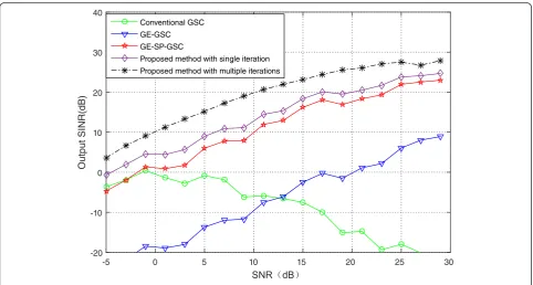
5.4 Simulation of output SINR versus input SNR
In the fourth example, the effect caused by different in-put SNR in the presence of DOA mismatch has been presented. The input SNR of the desired signal changes
from−5 to 30 dB. The desired signal’s DOA mismatch is assumed to be a random variable uniformly distributed from−8° to 8°. The remaining simulation conditions are the same as the first example. Figure 4 displays the output SINR of all five methods versus the input SNR. It can be seen from Fig. 4 that the proposed method with cyclic it-eration outperforms the others in terms of the output SINR due to its ability to accurately estimate the steering vectors over the main and auxiliary arrays. The conven-tional GSC outperforms the GE-GSC and GE-SP-GSC at Fig. 5The output SINR versus SNR in the presence of amplitude and phase errors
cycle iteration index
2 3 4 5 6 7
0 0.25 0.5 0.75 1 1.5 2 2.5 3
SNR = -20dB SNR = -15dB SNR = -10dB SNR = -5dB SNR = 0dB SNR = 5dB
low SNR. However, when the input SNR increases, the performance of the conventional GSC degrades dramat-ically mainly due to the SOI cancellation upgrading. Moreover, we also perform the CR versus the input SNR in the presence of amplitude and phase error. The phase errors are subject to the uniform distribution ranged from −90° to 90°. Meanwhile, the amplitude er-rors are assumed to follow the Gaussian distribution with variance of 0.09. The simulation results are shown in Fig. 5. From the figure, we can see, as the amplitude and phase errors exist, the anti-interference performance of each approach deteriorates in varying degrees. Nevertheless, the proposed algorithm still outperforms the others, which presents a demonstration of validity in practical usage.
5.5 Simulation of convergence curve
In the last example, the simulation of the cycle iterative convergence in different input SNR scenarios has been made. The DOA mismatch of the desired signal is a ran-dom variable with uniform distribution from −6° to 6°. The rest of the parameters remain unchanged with the first example. Without loss of generality, we define the initial terms as^a0
a;0ð Þ ¼θ a^a;0ð Þθ0 andw^0m¼wpreto calcu-late the iterative error δ. For the sake of convenience to observe, the result of the first iterative error has been neglected which is commonly large due to the random DOA mismatch. As shown in Fig. 6, the number of itera-tions of the proposed method slightly changes along with the input SNR. Although more cycle iterations may be re-quired when the SNR descends, the entire numbers of cycle iterations are still very small, which makes the pro-posed method effective in terms of implementation.
6 Conclusions
In this paper, we present one effective robust form of GSC against the desired signal’s steering vector caused by DOA mismatch. With the orthogonal matrices properly con-structed, the estimations of steering vectors over the main and auxiliary arrays, which are prevented from converging to interferences, have been achieved. Consequently, the SOI cancellation and the gain loss of the desired signal in the main array caused by the DOA mismatch can be sufficiently solved simultaneously. Simulation results demonstrate the effectiveness of the proposed method. Comparing with the conventional GSC and some modified approaches, the performance of the proposed method is nearly optimal over a wide range of SNR and the complexity is accept-able in terms of practical implementation.
Competing interests
The authors declare that they have no competing interests.
Acknowledgements
This work is supported by the National Natural Science Foundation of China (No. 61301262 and No. 61371184).
Received: 16 March 2016 Accepted: 2 May 2016
References
1. S Haykin, J Litva, T Shepherd,Radar array processing(Springer, New York, 1993) 2. LC Godara, Application of antenna arrays to mobile communications, part II: beam-forming and direction-of-arrival consideration. Proc. IEEE85(8), 1195–1245 (1997). doi:10.1109/5.622504
3. RJ Vaccaro, The past, present, and future of underwater acoustic signal processing. IEEE Signal Process. Mag.15(4), 21–51 (1998). doi:10.1109/79.689583 4. S Curletto, M Palmese, A Trucco, On the optimization of the transmitted
beam in contrast-enhanted ultrasound medical imaging. IEEE Trans. Instrum. Meas.56(4), 1239–1248 (2007). doi:10.1109/TIM.2007.900151
5. SW Ellingson, Beamforming and interference canceling with very large wideband arrays. IEEE Trans. Antennas Propag.51(6), 1338–1346 (2003). doi:10.1109/TAP.2003.812237
6. OL Frost, An algorithm for linearly constrained adaptive array processing. Proc. IEEE60, 926–935 (1972). doi:10.1109/PROC.1972.8817
7. SP Applebuam, Adaptive arrays. IEEE Trans. Antennas Propag.AP-24(5), 585–589 (1976). doi:10.1109/TAP.1976.1141417
8. KM Buckley, LJ Griffiths, An adaptive generalized sidelobe canceller with derivative constraints. IEEE Trans. Antennas Propag.34(3), 311–319 (1986). doi:10.1109/TAP.1986.1143832
9. J Ward, RT Compton Jr, Sidelobe level performance of adaptive sidelobe canceller arrays with elements reuse. IEEE Trans. Antennas Propag.
38(10), 1684–1693 (1990). doi:10.1109/8.59783
10. NK Jablon, Steady state analysis of the generalized sidelobe canceller by adaptive noise cancelling techniques. IEEE Trans. Antennas Propag.
34(3), 330–337 (1986). doi:10.1109/TAP.1986.1143833
11. LJ Griffiths, CW Jim, Alternative approach to linear constrained adaptive beamforming. IEEE Trans. Antennas Propag.30(1), 27–34 (1982). doi:10.1109/ TAP.1982.1142739
12. IJ Gupta, J Ward, Effects of desired signal on the performance of a sidelobe canceller. IEEE Trans. Antennas Propag.37(9), 1109–1115 (1989). doi:10.1109/ 8.35790
13. J Li, P Stoica, ZS Wang, On robust Capon beamforming and diagonal loading. IEEE Trans. Signal Process.51(7), 1702–1714 (2003). doi:10.1109/TSP. 2003.812831
14. SA Vorobyov, AB Gershman, ZQ Luo, Robust adaptive beamforming using worst-case performance optimization: a solution to the signal mismatch problem. IEEE Trans. Signal Process.51(2), 313–324 (2003). doi:10.1109/TSP. 2002.806865
15. A Hassanien, SA Vorobyov, KM Wong, Robust adaptive beamforming using sequential programming: an iterative solution to the mismatch problem. IEEE Signal Process. Lett.15, 733–736 (2008). doi:10.1109/LSP.2008.2001115 16. RG Lorez, SP Boyd, Robust minimum variance beamforming. IEEE Trans.
Signal Process.53(5), 1684–1696 (2005). doi:10.1109/TSP.2005.845436 17. S Shahbazpanahu, AB Gershman, ZQ Luo et al., Robust adaptive beamforming
for general-rank signal models. IEEE Trans. Signal Process.51(9), 2257–2269 (2003). doi:10.1109/TSP.2003.815395
18. JP Lie, S Wee, CMS See, Adaptive uncertainty based on iterative robust capon beamformer using steering vector mismatch estimation. IEEE Trans. Signal Process.59, 4483–4488 (2011). doi:10.1109/TSP.2011.2157500 19. LY Zhu, S Wee, HE Meng et al., Robust adaptive beamformers based on
worst-case optimization and constraints on magnitude response. IEEE Trans. Signal Process.57, 2615–2628 (2009). doi:10.1109/TSP.2009.2017004 20. M De, S De Nicola, Y Huang, S Zhang, A Farina, Adaptive detection and
estimation in the presence of useful signal and interference mismatches. IEEE Trans. Signal Process.57(2), 436–450 (2009). doi:10.1109/TSP.2008. 2008249
21. De Maio, Y Huang, DP Palomar, S Zhang, A Farina, Fractional QCQP with applications in ML steering direction estimation for radar detection. IEEE Trans. Signal Process.59(1), 172–185 (2011). doi:10.1109/TSP.2010.2087327
22. A Khabbazibasmenj, SA Vorobyov, A Hassanien, Robust adaptive beamforming based on steering vector estimation with as little as possible prior information. IEEE Signal Process. Lett.60(6), 2974–2987 (2012). doi:10.1109/TSP.2012.2189389 23. W Zhang, J Wang, S Wu, Robust Capon beamforming against large DOA
24. X Wang, JL Xie, ZS He,Robust sidelobe canceller against DOA mismatch
(ChinaSIP, Chengdu, 2015), pp. 310–313. doi:10.1109/ChinaSIP.2015.7230414 25. JR Schott,Matrix analysis for statistics, 2nd edn. (Wiley, New York, 2005) 26. YN Rao, JC Principe, An RLS type algorithm for generalized eigendecomposition.
IEEE Signal Process. Soc. 263–272 (2001). doi:10.1109/NNSP.2001.943131. Workshop on Neural Network for Signal Process
Submit your manuscript to a
journal and benefi t from:
7 Convenient online submission
7 Rigorous peer review
7 Immediate publication on acceptance
7 Open access: articles freely available online
7 High visibility within the fi eld
7 Retaining the copyright to your article