Design of TL Shape Rectangular Patch
Antenna for Global Positioning System (GPS)
Applications
M.Sheriff#1, M.Preethi#2, G.Shobana#3, P.Thanga Nandhini#4
Asst. Prof, Department of Electronics and Communication Engineering, Veltech, Chennai, India #1, Student, Department of Electronics and Communication Engineering, Veltech, Chennai, India #2,#3,#4
ABSTRACT: In today’s modern communication industry, antennas are the most important components required to create a communication. Microstrip antennas are the most suited for aerospace and mobile applications because of their low profile, light weight and low power handling capacity. A design of a rectangular microstrip patch antenna is developing for Global Positioning System applications. The Global Positioning System (GPS) is an aeronautics system that provides location and time information in all weather conditions, anywhere on or near the Earth. The proposed antenna is designed as TL shape with a transmission line to obtain a rectangular polarization by simulation software resulting with the frequency of 6 GHz. The antenna can be used for vehicle communication, aircraft tracking, cellular telephony, navigation etc.
KEYWORDS: Global positioning System, Microstrip patch antenna, rectangular patch, transmission line, rectangular polarization.
I. INTRODUCTION
Microstrip patch antenna are preferred than other antennas in today’s modern world scenario for their compatibility in Mobile Aircraft, Satellites because of very small sizes. Hence design and development of cost effective microstrip rectangular patch antenna has become an important research area. . Microstrip antennas are inexpensive to manufacture and they offer high performance with low profile and these antennas are ideal for GPS and tracking devices. . The proposed antenna is designed as TL shape with two rectangular patch and the antenna provides rectangular polarization with a transmission line by connecting the two patches. A low cost and high performance antennas are required for commercial and automotive industry application. To meet this requirements for GPS applications, authors are focused on low profile and compact size conventional patch antennas. The conventional patch antenna uses higher permittivity substrate to reduce the bandwidth. In this novel, a rectangular patch with dielectric substrate and copper substrate is presented to provide rectangular polarization for GPS applications. The patch antenna operates in a center frequency of 6GHz. The effectiveness of proposed antenna is verified by designing a patch antenna with different ground plane and simulated. Finally, the desired compact size and inexpensive antenna is designed with no complex feeding and matching circuits are required. The details of design, performance and results are discussed below.
II. ANTENNA DESIGN PROCESS
between them. A radiation box is etched on the top of the substrate and rectangular patch to produce excitations which is filled up with air material and the dimensions of the box is L3, W3 and h2.
Fig 1. geometry of the polarized rectangular patch antenna
Fig 1(a) side view of the antenna
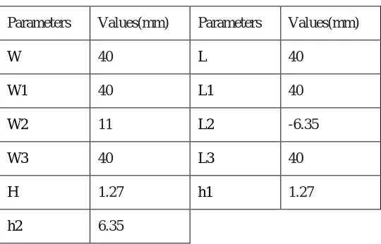
Table I
Parametric values of the patch antenna
Parameters Values(mm) Parameters Values(mm)
W 40 L 40
W1 40 L1 40
W2 11 L2 -6.35
W3 40 L3 40
Fig 2 overall mesh of the antenna
Fig 3. excitation analysis of rectangular transmission line
III. ANTENNA ANALYSIS
The is ξeff the effective permittivity of the substrate, and is the correction factor considering the presence of the
different dielectric materials used on the two sides of the folded patch. ξeff =1+q(ξr – 1)
The frequency for the proposed antenna can be calculated by using formula given as fc = 1/(2L(ξ0ξrμ0)1/2)
IV. RESULT AND DISCUSSION
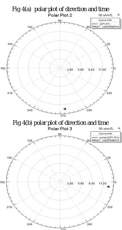
Fig 4(a) polar plot of direction and time
The 3D pattern of the antenna is shown in fig 5 with different magnitude values.
Fig 5 3D pattern of antenna
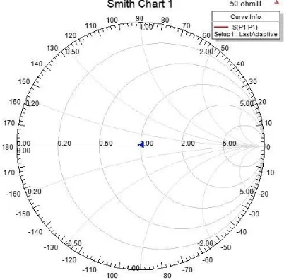
The impedence of the antenna is explained by using smith chart. The variation in impedence can be shown by using different direction parameters which is shown in fig 6.
Fig 6(b) smith chart in z parameter
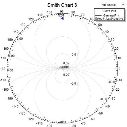
Fig (c) smith chart in gamma direction
V. CONCLUSION
2. “Miniature Folded Patch GPS Antenna for Vehicle Communication Devices” Hua-Ming Chen, Senior Member, IEEE, Yi-Fang Lin, Chien-Hung Chen, Chien-Yuan Pan, and You-Shiang Cai IEEE transaction on antennas and propagation, vol. 63, no. 5, may 2015.
3. Y. F. Lin, C. H. Lee, S. C. Pan, and H. M. Chen, “Proximity-fed circularly polarized slotted patch antenna for RFID handheld reader,” IEEE Trans. Antennas Propat., vol. 61, no. 10, pp. 5283–5286, 2013.
4. N. Guan, H. Chiba, Y. Yamaguchi, and H. Tayama, " A flat car-roof antenna module for phone and GPS applications," Proc. 2013 IEEEAPWC, pp. 299-302, 2013.
5. Y. K. Cho, H. D. Kang, S. Y. Hyun, and J. G. Yook, “Gain improvement topology using conical structure for jamming resilient GPS antennas,”
in Proc. IEEE Antennas Propag. Symp., Jul. 2012.
6. Nasimuddin, Z.N.Chen and Z. Quid, “ A compact circularly polarised cross shaped slotted microstrip antenna ,” IEEE Trans . Antennas Propag., vol. 60 no. 3, pp. 1584-1588, 2011
7. Y. F. Lin, Y. K. Wang, H. M. Chen, and Z. Z. Yang, “Circularly polarized crossed dipole antenna with phase delay lines for RFID handheld reader,” IEEE Trans. Antennas Propag., vol. 60, no. 3, pp. 1221–1227, 2011
8. K. Oh, B. Kim, and J. Choi, “Novel integrated GPS/RKES/PCS antenna for vehicular application,” IEEE Microw. Wireless Compon. Lett., vol. 9, pp. 405–408, 2010.
9. F. Mariottini, M. Albani, E. Toniolo, D. Amatori, and S. Maci, “Designof a compact GPS and SDARS integrated antenna for automotive applications,” IEEE AntennasWireless Propag. Lett., vol. 9, pp. 405–408,2010.