Optimization of Hydraulic Circuits Used in
Cotton Lint Bailing Press
Akshitam S. Sable1, Rajesh M.Metkar2
Department of Mechanical Engineering, Government College of Engineering, Amaravti (MH), India1
Assistant Professor, Department of Mechanical Engineering, Government College of Engineering,
Amravati (MH), India2
ABSTRACT:The design process is an interactive feedback process where the performance of the design is compared with the performance specification. Using an optimization strategy and a simulation model of the system it is possible to use a computer to optimize the system once the system layout is established. The total numbers of parameters of all components in a system are very large for handling them effectively by numerical optimization. The approach used here is to introduce a set of performance parameters that uniquely define the components if they are assumed to be optimized in some sense. This reduces the optimization problem to more realistic proportions and optimization of even rather complex system may be performed.
KEYWORDS:Automation Studio, Hydraulic Systems, Optimization.
I. INTRODUCTION
With fluctuations generated by the progress of science and technologies and by the worldwide usage trends, the hydraulic systems have known a considerable development, due to some major advantages those systems offer compared to the mechanical and even the electrical systems. The hydraulic system are the power transmitting assemblies which employing pressurized fluid to transmit energy from an energy generating source to the application area. The hydraulic system has oil as the working medium. Aside from the high and fully controllable value level of the energy, they also have the advantage of easily performing a continuous, accurate variation within the broad limits of the forces, couples, speed and position.
A) Component of hydraulic circuit
B) Nature of problem
1. As in working of cotton lint machine time plays as important role. So their always scope for reducing cycle time by application of software.
2. As machine works on conventional part and circuit. So with the help of high-tech software like automation studio which are fully developed software, improvement in the function of part and circuit can be done. Eventually it gives us higher productivity and reduce cycle time.
C) Purpose
The main purpose of this paper to optimize the cotton lint bale press machine and to increase the productivity of machine. To achieve this goal, Automation Studio software is used for a system design, animation and simulation.
D) Automation studio
It was created for the automation industry, specifically to fulfill training and testing requirements. The simulation utility makes Automation Studio an efficient tool for the certification of automated processes and programs. In the Automation Studio environment, all the design tools are readily accessible. The core system contains three utilities like a diagram editor, a project explorer, and a library explorer. The diagram editor allows to generate and simulate diagrams and create reports, while the project explorer handles file management and the classification of all documents associated with a simulation project. The Library Explorer supplies the symbols libraries necessary for the creation of the diagrams that make up projects. Finally, this software allows to document the project. The Automation Studio user documentation has a modular structure. The current Automation Studio contains information on the main functions of the project explorer, the library explorer, the diagram editor for the standard workshops on hydraulic, pneumatic, electrical controls, numerical, and scale diagrams and the simulation mode.
II. METHODOLOGY Methodology
The basic approach to design that we take in this section was introduced by R Henke (Fluid Power Systems and Circuits, Hydraulics and Pneumatics, 1983). We have, however, endeavored to streamline the preliminary steps in defining the hydraulic force (torque) profile and will introduce a set of criteria to assist in transferring information about the system to the actual placement of components to satisfy the circuit requirements. In the final analysis, there will be many possible solutions to the defined problems and each case really is unique. We shall attempt to provide very basic circuits which represent worst case scenarios and which can be optimized through compromise and redesign. A summary of the steps for design are as follows:
1. Design Circuit on Automation Studio Software.
2. Calculate the cycle time for existing model. 3. Apply regenerative circuit
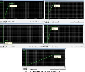
4. Plot linear position profiles at important parts of the circuit. 5. Calculate the cycle time from profile.
A) Design Circuit on Automation Studio Software
Fig.2.1Design of circuit in Automatiion Studio
Total cycle time with existing model by software = (Total cycle time of tramper cylinder) + (Total cycle time of pusher cylinder) + (Total cycle time of chamber locking cylinder) + (Total cycle time of RP cylinder )+ (Total cycle time of door less cylinder)
Total cycle time with existing model = 15.02*8+5.28*8+1.75+16.92+15.38 Total cycle time with existing model by software = 196.45 sec
C) Calculate the cycle time for existing model by Mathematically
1. Cylinder Ratio = (Head End Area)/(Head End Area - Rod End Area) = (Head End Area)/(Annular Area)
2. Cylinder Extend Speed without Regeneration
a) Extend Speed = (Pump Flow GPM*231)/(Head End Area)
b) Retraction speed = (Pump Flow GPM*231)/(Annular Area)
c) Speed with regeneration = (Pump Flow GPM*231)/(Rod End Area)
Cylinder Name Door less cylinder Pusher cylinder Tramper cylinder
RP cylinder Chamber locking
Extended speed
118.72 in/min
746 in/min 476.09
in/min
179 in/min 179 in/min
Extended Time
14.12 sec 3.89 sec 11.41 sec 8.18 sec 1.45 sec
Retraction speed 328.68 in/min 1100 In/min 744.2 in/min 262.5 in/min 411.27 in/min Retraction Time
5.10 sec 2.64 sec 7.3 sec 8.1 sec 0.63 sec
Table 2.1 Cycle time Calculation
Total cycle time with existing model by mathematically = (Total cycle time of tramper cylinder) + (Total cycle time of pusher cylinder) + (Total cycle time of chamber locking cylinder) + (Total cycle time of RP cylinder )+ (Total cycle time of door less cylinder)
Total cycle time with existing model = 18.71*8+6.53*8+19.22+16.28+2.08 Total cycle time with existing model by mathematically =239.5 sec
D) Apply regenerative circuit
In existing model, the oil which is at other end of cylinder is goes to the tank when cylinder extend. These pressurized oil get wasted. Due to these the cycle time of process is high. So I have done a changes liked that the oil from other end is passed through the main line of pressurized oil which coming from pump. Due to these the flow fluid increase and ultimately the rate of pressurized fluid increase. Because of these the velocity of the piston during extension increases and cycle time process is decreases. This phenomenon is called as “Regeneration".
Fig 2.3 Regenerative Concept
Fig 2.4 Changes in circuit
F) Calculate the cycle time for existing model by Software
Total cycle time with regenerative principal by software = (Total cycle time of tramper cylinder) + (Total cycle time of pusher cylinder) + (Total cycle time of chamber locking cylinder) + (Total cycle time of RP cylinder )+ (Total cycle time of door less cylinder)
Total cycle time with regenerative principal = 9.26*8+3.24*8+1.23+10.07+11.47 Total cycle time with regenerative principal by software =123.4 sec
G) Calculate the cycle time for existing model by Mathematically
Cylinder Name Door less cylinder Pusher cylinder Tramper cylinder
RP cylinder Chamber locking
Extended speed 185.87 in/min 2347.56 in/min 1321.51 in/min 563.41 in/min 317.16 in/min Extended Time
9.02 sec 1.23 sec 4.11 sec 3.81 sec 0.81 sec
Table 2.2Cycle time Calculation
Total cycle time with regenerative principal by mathematically = (Total cycle time of tramper cylinder) + (Total cycle time of pusher cylinder) + (Total cycle time of chamber locking cylinder) + (Total cycle time of RP cylinder )+ (Total cycle time of door less cylinder)
Total cycle time with regenerative principal by mathematically = 11.41*8+3.87*8+1.44+11.91+14.12 Total cycle time with regenerative principal by mathematically =149.71 sec
H) Comparison of cycle time
Fig.2.6Comparison of cycle time
III. RESULTSANDANALYSIS
During designing of hydraulic bale press machine method was convectional. As it is design by convectional way there is always scope for improvement in hydraulic bale press machine. Now in this paper the software that is Automation Studio used and in which all the design tools are readily accessible. The simulation utility makes Automation Studio an efficient tool for the certification of automated processes and programs. In Automation Studio reconstruct of circuit done and simulate. During simulation it observed that the time required for complete cycle was high. Due to these the productivity and efficiency of machine is low.
the flow of oil to head end piston increase which automatically increase the extend speed of cylinder. By using regeneration concept, the cycle time of process is decrease by 73.05 seconds. As the cycle time of machine is decrease the productivity of machine also increases which ultimately increase the efficiency of machine and also the profit of company is increase.
Total quantity of bale in working hour before regeneration = (total working hour)/ (time required for single bale) = (8*60*60)/ 196.45
Total quantity of bale in working hour before regeneration = 147 bale
Total quantity of bale in working hour after regeneration = (total working hour)/ (time required for single bale) = (8*60*60)/ 123.4
Total quantity of bale in working hour after regeneration = 233 bale
Due to regeneration model the number bale increases by 86.
IV. CONCLUSION
The reduction of cycle time is done in hydraulic bale press machine by using high-tech tool like Automation Studio. This is achieved by using modification done in existing model. The existing model contains convectional component and these component is replace by concept regeneration model. By using regeneration concept, the cycle time reduce by 37.18 percent. After changes in hydraulic cotton lint bale press machine, the productivity is further increases.
REFERENCES
[1]Pascu Marius, Optimizing The Hydraulic Systems Using The Simhydraulics programming Environment, VasileAlecsandri, University of Bacau, Romania. Volume 16, No. 4, 2010.
[2]Hui-linQu, Yi-xiong FENG, Yi-congGao, Jian-rong Tan, Optimization design of guiding device on hydraulic press column based on Axiomatic Design Theory, State Key Laboratory of Fluid Power and Mechatronic Systems, Zhejiang University, Hangzhou 310027, China, 2016.