Comparative Analysis of Pi and ANN
Controller for iUPQC
P. Siva Shunmuga Sudar1, Dr.D. Mary 2
P.G. Student, Department of EEE, Government College of Technology, Coimbatore, Tamil Nadu, India.1
Professor, Department of EEE, Government College of Technology, Coimbatore, Tamil Nadu, India.2
ABSTRACT: This paper presents acomparison between the PI controller and Artificial Neural Network controller for the dual topology of the Unified Power Quality Conditioner (iUPQC) whose application can be extended in terms of power quality compensation, as well as in microgrid applications. Despite the conventional UPQC power quality features which includevoltage sag/swell compensation, the iUPQC will also provide reactive power support to regulate not only the load-bus voltage, but also the voltage at the grid-side bus. In other words, the iUPQC will work as a STATCOM at the grid side, while providing the conventional UPQC compensations at the load or microgrid side. Simulation models were created for PI and ANN controller using MATLAB(r2014a) software to validate the theoretical considerations.
KEYWORDS: Unified Power Quality Conditioner (UPQC), Artificial Neural Network, PI Controller, voltage compensation.
I. INTRODUCTION
Power-electronics devices have brought about great technological improvements recently. However, the increase in the number of power-electronics-driven loads used generally in the industry sector has brought about serious power quality problems. On the other hand, power-electronics-driven loads usually require ideal sinusoidal supply voltage for their proper functioning, whereas they are the most responsible ones for abnormal harmonic currents level in the distribution system.
In this scenario, devices that can effectively mitigate these drawbacks have been developed over the years. One of the solutions involve a flexible compensator, known as the unified power quality conditioner (UPQC) and the static synchronous compensator (STATCOM).
The power circuit of a UPQC consists of a combination of two filters namely a shunt active filter and a series active filter that are connected in a back-to-back configuration. The main advantage of this combination is that it allows the simultaneous compensation of the load current and the supply voltage, so that the compensated current being drawn from the grid and the compensated supply voltage that is to be delivered to the load are kept balanced and sinusoidal. In the dual topology of the UPQC, where the shunt active filter behaves as an ac-voltage source and the series one as an ac-current source.
The STATCOM has been used widely in transmission networks to regulate the voltage by means of dynamic reactive power compensation. Nowadays, the STATCOM is largely used for voltage regulation, whereas the UPQC and the iUPQC have been selected as solution for more specific applications.
II. MODIFIED iUPQC
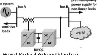
B must be regulated, so that there is a proper supply to the sensitive loads and the nonlinear loads. The effects caused by the harmonic currents drawn by the nonlinear loads should be mitigated, in order to avoid the harmonic voltage propagation to bus A.
Figure 1 Electrical System with two buses.
The use of a STATCOM alone to guarantee the voltage regulation at bus A is not enough because the harmonic currents drawn by the nonlinear loads are not mitigated only with the STATCOM. Instead, a UPQC or an iUPQC between bus A and bus B can not only compensate the harmonic currents of the nonlinear loads but also compensate the voltage at bus B, in terms of voltage harmonics, unbalance, and sag/swell. However, this is still not enough to guarantee the voltage regulation at bus A. Therefore, to achieve all the desired goals, a STATCOM at bus A and a UPQC (or an iUPQC) between buses A and B should be employed. But, the cost of this solution would be unreasonably high. An alternate solution would be the use of a modified iUPQC controller to provide the reactive power support to bus A. The modified iUPQC serves as an intertie between the buses A and B. Moreover, the microgrid connected to the bus B could be a complex system comprising distributed generation, energy management system, and other control systems.
The modified iUPQC can provide the following functionalities:
a) “Smart” circuit breaker as an intertie between the grid and the microgrid. b) Energy and power flow control between the grid and the microgrid. c) Reactive power support at bus A of the power system.
d) Voltage/frequency support at bus B of the microgrid.
e) Harmonic voltage and current isolation between bus A and bus B. f) Voltage and current imbalance compensation.
The configuration of modified iUPQC is shown in Figure 2.
Figure 2 Modified iUPQC
bus B (iL), and the voltage vDC of the common dc link. The outputs are the shunt-voltage reference and the
series-current reference to the pulse width modulation (PWM) controllers. The voltage and series-current PWM controllers can be simply employed, or be improved further so as to deal better with voltage and current imbalance and harmonics. The voltage at bus Bis imposed by the shunt converter. Therefore, it is necessary to synthesize sinusoidal voltages with nominal amplitude and frequency. Consequently, the signals sent to the PWM controller are the phase-locked loop (PLL) outputs whose amplitude is equal to 1 p.u.
In the iUPQC approach as presented, the voltage reference of the shunt-converter can be either the PLL outputs or the fundamental positive-sequence component VA+1 of the grid voltage. The use of VA+1 in the controller is to minimize the power that is circulating through the series and the shunt converters, under normal operation, while the amplitude of the grid voltage is kept within an acceptable range of magnitude. However, this is not the case here, in the modified iUPQC controller, since the grid voltage will also be regulated by the modified iUPQC. In other words, both buses will be regulated independently so that their reference values can be tracked.
Figure 3 Improved iUPQC controller.
The current drawn from the grid bus (bus A) is synthesized by the series converter. In the original approach of iUPQC, this current is calculated through the average active power required by the loads PLplus the power PLoss. The load active
power can be estimated by,
Where, iL_α, iL_βare the load currents, and V+1_α, V+1_β are the voltage reference values for the shunt converter. The
average active power (PL) is obtained with the help of a low- pass filter. The losses in the power converters and the circulating power to provide energy balance inside the iUPQC can be calculated indirectly from the measurement of the dc-link voltage. In other words, a proportional– integral (PI) controller is used to determine the power signal PLoss, by
comparison of the measured dc voltage VDC with its reference value. The additional control loop to provide voltage
regulation like a STATCOM at the grid bus can be represented by the control signal QSTATCOM. This control signal is
The sum of the power signals PL and PLOSS composes the active power control variable for the series converter of the
iUPQC.
IV. ARTIFICIAL NEURAL NETWORK
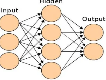
An artificial neural network (ANN), usually called neural network (NN), is a mathematical model or computational model that is inspired by the structure and/or functional aspects of biological neural networks.ANN network consists of the input layer, hidden layer and the output layer.
Figure 4 Three layer neural network
The graphical representation of neurons in ANN is shown in the Figure 5
Figure 5 Graphical representation of neuron in ANN
There are several types of architecture of NNs. However, the two most widely used NNs are Feed forward networks and Recurrent networks. In a feed forward network, information flows in one direction along connecting pathways, from the input layer via the hidden layers to the final output layer. There is no feedback (loops) i.e., the output of any layer does not affect that same or preceding layer. Feed-forward neural networks, where the data from input to output units is strictly feedforward. The data processing can extend over multiple (layers of) units, but no feedback connections are present.
nftool (neural network fitting tool)provides a graphical user interface for designing and training a feedforward neural network for solving approximation (fitting) problems. The networks created by nftool are characterized by:
a) One hidden layer (the number of hidden units can be changed by the user; the default value is 20)
b) The hidden units have a sigmoidal activation function (tansig or logsig) while the output units have a linear activation function
c) The training algorithm is Backpropagation based on a Levenberg-Marquardt minimization method (the corresponding Matlab function is trainlm
The learning process is controlled by a cross-validation technique based on a random division of the initial set of data in 3 subsets: for training (weights adjustment), for learning process control (validation) and for evaluation of the quality of approximation (testing). The quality of the approximation can be evaluated by:
a) Mean Squared Error (MSE): it expresses the difference between to correct otputs and those provided by the network; the approximation is better if MSE is smaller (closer to 0)
b) Pearson’s Correlation Coefficient (R): it measures the correlation between the correct outputs and those provided by the network; as R is closer to 1 as the approximation is better.
V. SIMULATION RESULTS
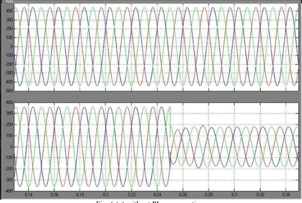
Figure shows the simulation results with PI and ANN controller for iUPQC.Figure6represents the grid voltage obtained (a) without PI controller and (b) with PI controller.
Fig. 6(b) with PI compensation
Figure 7 represents the grid voltage obtained for linear loads (a) without ANN controller and (b) with ANN controller.
Fig. 7(a) Without ANN controller for linear load Fig. 7 (b) With ANN controller for linear load
VI. CONCLUSION
Different simulation models were created using PI and ANN controllers. The effect of PI controller in voltage compensation was analyzed. Simulation models were created using ANN controllers. The effect of ANN controller in voltage compensation while connecting linear and non- linear loads were analyzed.
The simulation results show that the performance of the Artificial Neural Network is superior compared to that of the conventional PI controller. The proposed system of improved UPQC has the advantages of high reactive power compensation, power quality compensation, and critical load compensation. Applications of the proposed system are Smart grids, Microgrids, and distributed generation and energy storage system to better deal with inherent variability of renewable resources such as wind and solar.
REFERENCES
[1] Bruno W. França, Leonardo F. da Silva, Maynara A. Aredes, and MaurícioAredes, “An Improved iUPQC Controller to Provide Additional Grid-Voltage Regulation as a STATCOM”, IEEE Transactions On Industrial Electronics.
[2] V. Khadkikar and A. Chandra, "A New Control Philosophy for a Unified Power Quality Conditioner (UPQC) to Coordinate Load-Reactive Power Demand Between Shunt and Series Inverters," IEEE Trans. Power Del.,vol. 23, no. 4, pp. 2522-2534, Oct. 2008.
[3] KianHoong Kwan, Ping Lam So, and Yun Chung Chu, "An Output Regulation-Based Unified Power Quality Conditioner With Kalman Filters,"
IEEE Trans. Ind. Electron., vol. 59, no. 11, pp. 4248-4262, Nov.2012.
[4] A. Mokhtatpour and H.A. Shayanfar, "Power Quality Compensation as Well as Power Flow Control Using of Unified Power Quality Conditioner," in Power and Energy Engineering Conference (APPEEC),2011 Asia-Pacific, 2011, pp. 1-4.
[5] J.A. Munoz et al., "Design of a Discrete-Time Linear Control Strategy for
a Multicell UPQC," IEEE Trans. Ind. Electron., vol. 59, no. 10, pp. 3797-3807, Oct. 2012.
[6] V. Khadkikar and A. Chandra, "UPQC-S: A Novel Concept of Simultaneous Voltage Sag/Swell and Load Reactive Power Compensations Utilizing Series Inverter of UPQC," IEEE Trans. Power Electron., vol. 26, no. 9, pp. 2414-2425, 2011.
[7] V. Khadkikar, "Enhancing Electric Power Quality Using UPQC: A Comprehensive Overview," IEEE Trans. Power Electron., vol. 27, no. 5,pp. 2284-2297, 2012.
[8] L. G B Rolim et al., "Custom Power Interfaces for Renewable Energy Sources," in Industrial Electronics, 2007. ISIE 2007. IEEE International Symposium on, 2007, pp. 2673-2678.
[9] N. Voraphonpiput and S. Chatratana, "STATCOM Analysis and Controller Design for Power System Voltage Regulation," in Transmission and Distribution Conference and Exhibition: Asia and Pacific, 2005 IEEE/PES, 2005, pp. 1-6.
[10] J. J. Sanchez-Gasca, N. W. Miller, E.V. Larsen, A. Edris, and D. A.Bradshaw, "Potential benefits of STATCOM application to improve generation station performance," in Transmission and Distribution Conference and Exposition, 2001 IEEE/PES, vol. 2, 2001, pp. 1123-1128 vol.2. [11] A.P. Jayam, N.K. Ardeshna, and B.H. Chowdhury, "Application of STATCOM for improved reliability of power grid containing a wind turbine," in Power and Energy Society General Meeting – Conversion and Delivery of Electrical Energy in the 21st Century, 2008 IEEE, 2008, pp. 1-7.
[12] C.A Sepulveda, J.A Munoz, J.R. Espinoza, M.E. Figueroa, and P.E. Melin, "All-on-Chip dq-Frame Based D-STATCOM Control Implementation in a Low-Cost FPGA," IEEE Trans. Ind. Electron., vol.60, no. 2, pp. 659-669, 2013.
[13] B. Singh and S.R. Arya, "Back-Propagation Control Algorithm for Power
Quality Improvement Using DSTATCOM," IEEE Trans. Ind. Electron., vol. 61, no. 3, pp. 1204-1212, 2014.
[14]M. Aredes and R.M. Fernandes, "A dual topology of Unified Power Quality Conditioner: The iUPQC," in Power Electronics and Applications, 2009. EPE '09. 13th European Conference on, 2009, pp. 1-10.
[15]M. Aredes and R.M. Fernandes, "A unified power quality conditioner with voltage SAG/SWELL compensation capability," in Power Electronics Conference, 2009. COBEP '09. Brazilian, 2009, pp. 218-224.
[16] B.W. Franca and M. Aredes, "Comparisons between the UPQC and its dual topology (iUPQC) in dynamic response and steady-state," in IECON 2011 - 37th Annual Conference on IEEE Industrial Electronics Society, 2011, pp. 1232-1237.