18th International Conference on Structural Mechanics in Reactor Technology (SMiRT 18) Beijing, China, August 7-12, 2005 SMiRT18-K01-5
SITE-SPECIFIC ISSUES RELATED TO STRUCTURAL / SEISMIC
DESIGN OF AN UNDERGROUND INDEPENDENT SPENT FUEL
STORAGE INSTALLATION (ISFSI)
Bhasker P. Tripathi, P. E.
United States Nuclear Regulatory Commission
Phone: 301-415-4092, Fax: 301-415-8555
E-mail: bpt@nrc.gov
ABSTRACT
Utilities owning and operating commercial nuclear power plants (NPP) in USA may choose to build an underground Independent Spent Fuel Storage Installation (ISFSI) to store the spent nuclear fuels. The regulatory requirements and other guidance are based on 10 CFR Part 72, Regulatory Guide RG 3.73, Standard Review Plans NUREG-1536 and NUREG-1567, and Interim staff Guidance (ISG) documents as applicable.
Structures, Systems, and Components (SSCs) classified as important to safety are designed to withstand the effects of site-specific environmental conditions and natural phenomena such as earthquake, tornado, flood, etc. An underground ISFSI for storage of spent nuclear fuel, presents some unique analysis and design challenges. This paper will briefly address some of these challenges and discuss site-specific loads, including seismic for the ISFSI design.
Keywords: ISFSI, Structural / Seismic, Underground Concrete Vault, Design Loads
1. INTRODUCTION
There are approximately 102 nuclear power plants operating in the United States of America (USA). Most of the nuclear spent fuel is now being stored in the high-density “wet” spent fuel pools adjacent to reactors. As pools begins to approach their storage limits, independent spent fuel storage installations (ISFSIs) are being built at the existing nuclear power plant sites and a few away from the reactor site, to accommodate the growing inventory of spent fuel. In the USA the ISFSIs licensed (and those that will be built in future) store the spent fuel in dry casks approved for this purpose by the United States Nuclear Regulatory Commission (NRC). Typically, these storage asks are placed on reinforced concrete pads within the secure perimeter of the power plant site.
Spent nuclear fuel storage casks and systems must be designed to meet four safety objectives: a) Ensure that doses from spent fuel in the casks and systems are less than limits prescribed in the regulations, b) maintain sub-criticality under all credible conditions, c) ensure that there is adequate confinement and containment under all credible conditions of storage, and d) allow retrieval of the spent fuel from the storage systems. Loads and loading conditions for Normal, Off-normal, and Accident conditions need to be in compliance with requirements of 10 CFR Part 72 (Ref. 1). ISFSIs across the nation have spent nuclear fuel stored in dry cask storage system (DCSS) that has been licensed by NRC. Currently the initial license life is 20 years, which may be extended for 20 more years if found acceptable to NRC.
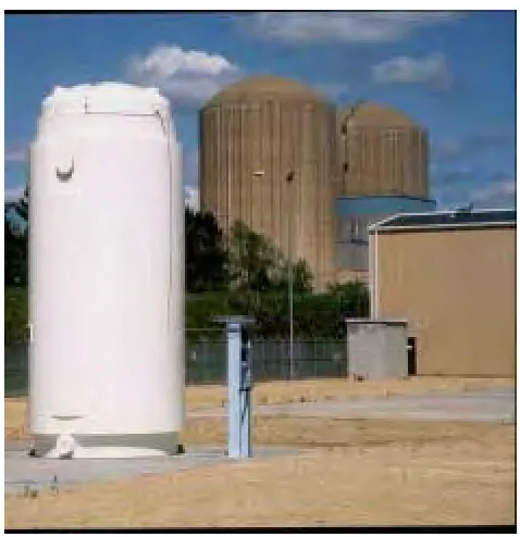
tornado, high wind, flood, earthquake, tsunami, etc., among other loads, similar to those stored above ground. A typical vertical storage module is shown in Figure 1.
Figure 1 Typical Vertical DCSS
2.0 SITE-SPECIFIC ISSUES
This paper will discuss some of the site-specific issues related to the structural design of an underground ISFSI structure, including seismic design. One of the variations of this concept that is not the subject of this paper is an above ground facility covered with soil, gravel, and rocks. Underground ISFSIs may be designed and built in the near future, as this option could gain popularity among the potential applicants, as they may be perceived by some, as providing additional protection from man-made events such as: blast and other loads. Current NRC regulations (based on prescriptive requirements) for design and construction of ISFSIs are evolving to become more risk-informed. Performance based specifications and requirements are yet not available for these types of structures.
An application (site-specific) to design and build an ISFSI to store spent fuel at a Nuclear Power Plant is currently under review by the USNRC staff. The ISFSI is unique, since it is to be built underground close to an ocean coastline, and in a highly active seismic zone. The consideration and application of the seismically induced loads will be discussed later. Some of the loads under normal, off-normal and accident conditions for verifying adequacy of structural design are as follows:
Handling Accident and Tip Over Pressure
Temperature and Solar Radiation Blockage of Vent Ducts Inlet Snow and Ice
Flood Tsunami
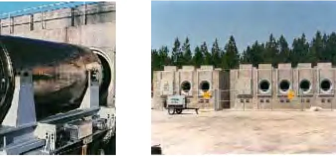
Currently, the NRC approved DCSS are either vertical modules, or horizontal modules, made of steel, concrete and combinations of these and other materials. A typical horizontal cask is shown in Figure 2.
Figure 2 Typical Horizontal DCSS
The regulatory licensing requirements for ISFSIs are governed by 10 CFR Part 72 (Ref. 1). Regulatory Guide 1.76 (Ref. 2), Regulatory Guide 3.73 (Ref. 3), NUREG-1536 (Ref. 4), NUREG-1567 (Ref. 5), and applicable Interim Staff Guidance are among the guidance provided for the storage and design of ISFSIs. The requirements per regulations have to be met, as a minimum, regardless whether the ISFSI is above or below ground. The underground ISFSI has by its very nature, different design requirements than above ground facilities that will pose additional design challenges. The discussion that follows will briefly address the loads listed above.
3.0 LOADS OTHER THAN SEISMIC
Handling loads occur during emplacement and removal of the Multi-purpose Canister (MPC), or the storage overpack, as the case may be, into the concrete cavity, (vault). The emplacement and removal of the top lid on the storage cask placed underground will create unique situations that are normally not encountered for an above ground ISFSI. The guidance provided in the Reg. Guide 3.61 (Ref. 7) for lifting operation will be applicable as appropriate. Due to the nature of the underground configuration depending on the clearance between the outer shell of the storage module and the concrete cavity, tip-over scenarios could be precluded as the surrounding sub-grade will provide sufficient lateral support.
The structural evaluation of the storage cask vessel for off-normal internal pressure conditions will have to be verified to ensure that the pressure boundary stresses are within the allowable limits.
The thermal analyses with the cask inside the concrete cavity (vault) and the cask lid installed for long-term storage, values of maximum annual average ambient temperature, soil temperature, and the site-specific incident solar radiation (insolation) data applicable to the ISFSI site for normal, off-normal, and extreme (accident) conditions may be different than those used in the thermal analysis for aboveground storage modules. These parameters need to be verified to ensure that they are within the permissible bounding limits. The load factor for internal moments and forces caused by temperature distributions within the concrete structure that occurs due to normal operating or off-normal conditions specified by ACI 349-01 is 1.05. NRC Reg. Guide 1.142 (Ref. 8) recommend a factor of 1.2, and NUREG 1536 (Ref. 4) suggests using a factor of 1.275 to be used in load combination when tornado is combined with dead load, live load, and load due to weight and pressure of soil, water in soil, or other materials. This load combination could turn out to be more critical, especially for underground ISFSIs.
The underground construction will require evaluation of potential flood conditions. Water that finds its way into the concrete cavity (vault) through the inlet ducts could come into contact with MPC, will not be drained by gravity, which is the case for the above ground system. Blockage of inlet ducts by trapped water, and waterborne debris like sand or soil could cause component or fuel cladding temperatures to exceed the allowable limits.
lead to undesirable freezing of the soil in the nearby surroundings of the underground ISFSI and could create conditions that must be evaluated. The surface topography and hydrology around the ISFSI area and the relation with the existing drainage system need to be thoroughly evaluated to ensure that flooding of ISFSI structure will not occur. The elevation of the ISFSI relative to other existing structures nearby will help determine if there exists any potential of inundation due to design basis flood.
Figure 3 “Tsunami” Ocean Waves Triggered by Seismic Event
A typical tsunami wave (Figure 3) has a very long wavelength (bottom figure) when they come ashore like a long lasting flood wave, rather than the breaking surf (top figure) we commonly see at the beaches. The devastating effects of such flooding on an underground ISFSI must be addressed.The 9.3 magnitude earthquake of December 2004 in the Indian Ocean had wide ranging devastating effects, not just in the nearby countries of Indonesia, Thailand, Andaman and Nicobar Islands of the Indian Ocean, but as far away as the East coast of Africa. Besides the human tolls in tens and thousands, all sorts of structures were demolished, and a nuclear power plant in the State of Tamilnadu, in South East coast of India was shutdown for safety as a precaution.
The top elevation of the ISFSI cavity (vault) with respect to mean sea level elevation, bounding estimates for distant tsunamis, as well as locally generated tsunamis associated with various seismic zones based on historical and potential earthquakes need to be considered. The actual run-up height of tsunami, potential of inundation due to high and low tides including wave run-ups for storms occurring coincident with the tsunami should be taken into account when verifying the adequacy of the underground ISFSI structure.
The underground ISFSI design must ensure that the damaging tsunami wave forces cannot lift the entire structure above ground and put the structure in an unanalyzed condition. The storage cask itself is designed to withstand the static pressure forces from deepwater submergence in as required by the regulations. However, the underground ISFSI concrete structure could be vulnerable to the flowing waters and water-borne debris created by tsunami waves. The entire soil and sub-soil supporting the base mat could degrade from tsunami forces and must be considered when evaluating the stability of the ISFSI.
NRC Regulatory Guide 1.76 (Ref. 2) identifies maximum wind speeds, tornado wind speeds, and design basis tornado missiles to be considered for nuclear safety related structures. Other references for this design basis event are ANSI/ANS (Ref. 9) and ASCE standards (Ref. 10). Although dry storage cask designs are reviewed, approved and licensed by NRC, it is incumbent upon the ISFSI license holder to ensure that site-specific licensing basis tornado loads are appropriately addressed. The following, as applicable need to be addressed: tornado rotational, and translational wind, maximum wind speed, tornado differential pressure load, tornado missiles impact load.
The method of combining the effective tornado wind, differential pressure, and missile impact loads are in accordance with NUREG-0800 (Ref. 11), and consistent with the defense-in-depth approach. Obvious, and logical conclusion based on intuition would be, that since ISFSIs are located underground, one does not need to worry about these loads. However, the portion of the concrete cavity (vault) that protrudes above the ground surface, the top lid of the cask, etc., could be in a low trajectory with both a horizontal and vertical velocity components, could strike the exposed horizontal surface of the apron in a glancing blow and needs to be evaluated.
4.0 SEISMIC DESIGN
Regulatory Guide 3.73 (Ref. 3), suggests that a Probabilistic Seismic Hazard Analysis (PSHA) should be performed because it can systematically take into account uncertainties and alternative hypotheses. These uncertainties are in the form of both aleatory, and epistemic uncertainty. Aleatory uncertainty leads to the shape of the hazard curve, and epistemic uncertainty leads to alternative hazard curves. The source models, ground motion attenuations, and the site response models should be consistent with the Senior Seismic Hazard Analysis Committee (SSHAC) (Ref. 12) guidelines.
There are number of complexities involved in understanding the actual wave propagation through a 3-D geologic structure. The horizontal ground motions influences seismic design of massive underground concrete structures. However, some in the industry are of the opinion that the vertical ground motions, in general, do not have a significant influence on these structures, especially those that have limited openings, such as underground ISFSIs. This argument may not be true in all situations. The increased vertical load on the reinforced concrete mat underneath the storage cask from a downward directed vertical seismic acceleration would affect the structural integrity of the ISFSI.
Vertical ground motions also could have detrimental effects on the stability of slopes that may be present nearby the underground ISFSI location. The inertial response of the sliding slope mass could change due to vertical ground motions. It can also either increase or decrease the driving and resisting forces along the potential sliding plane, which further can affect the yield acceleration.
Another unique feature for these underground ISFSI structures is, that there are no cantilever structural elements, nor any structural components with long spans. The guidance provided in the RG 3.73 (Ref. 3) calls for the analysis of the casks and the ISFSI structure to use the spectra and time histories in the three orthogonal directions. For the geo-technical analysis, especially the vertical ground motions may influence the seismic induced displacements of the underground structure. Depending upon the magnitude of the peak ground acceleration at a specific site, this may have to be included in the deformation analysis using pseudo-static analysis, or the so-called Newmark sliding block analysis.
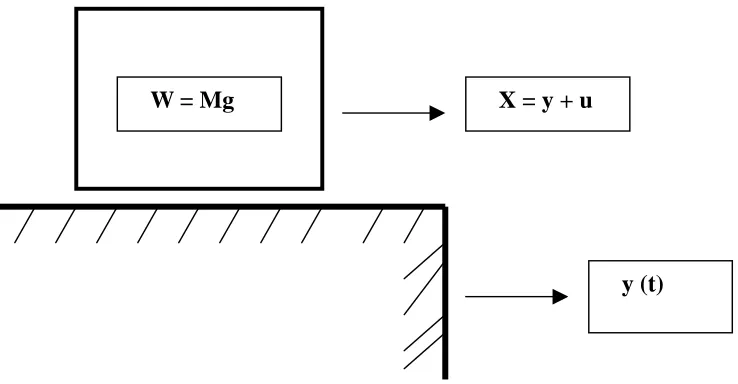
Dr. Newmark developed a stick-slip sliding block concept (Ref. 13) in 1965, which is still generally followed to calculate seismically induced displacement on slopes. The potential sliding mass on a slope during an earthquake is simplified to a block (with weight W) sliding on a horizontally moving plane. See Figure 4 below.
y (t)
W = Mg
X = y + u
Figure 4 Block on a Sliding Base
[1]
beyond which the block will start to ‘slip’, is known as the yield acceleration. At some point in time when the seismic excitation decelerates to below the resistance between the block and its foundation, the block re-attaches to the foundation. Eventually when the seismic wave has passed through, the movement of the foundation will stop, and the net differential movement between the block and the foundation is defined as the seismically induced displacement.
The original Newmark approach considered only the horizontal pulse, which needs to be modified to include the vertical excitation. The yield acceleration, which was assumed to be constant over time, should be expressed as function of the slope angle, friction angle between the block and the base, cohesion between the block and the base, and the vertical acceleration. Yan et al (Ref. 14) has shown that if the vertical ground motions are time-dependent variable, the yield acceleration will also be time-dependent. If the vertical acceleration is acting upward or opposing the gravitational forces, it will have a positive influence on the yield acceleration and increase its value. The potential effects of such phenomena on the structural integrity should be considered for an underground ISFSI. Another very important consideration for these underground ISFSIs is potential of seismically induced liquefaction of subsoil. Since the late 1980s, it has been popular to develop liquefaction evaluation procedure based on in-situ shear wave velocity (Vs) measurements. Although there are several benefits of using this approach, recent studies in the field of geo-technical engineering have shown that there are several drawbacks of this approach. One of the drawbacks is the lack of theoretical justification to use small strain properties (shear wave velocities) to interpret large strain phenomenon (liquefaction). Thorough geo-technical investigations of subsoil conditions, and analysis/design reports, peer reviewed by industry experts may be called for, in certain site-specific underground ISFSIs. The NRC Regulatory Guide 1.198 (Ref. 15) acknowledges that the phenomenon of liquefaction is most predominant in fluvial-alluvial deposits, Aeolian sands and silts, beach sands, reclaimed land and un-compacted hydraulic fills, and provides further guidelines and criteria that are based on physical properties rather than on blowcounts to evaluate liquefaction or strength loss susceptibility of fine-grained soils. Recent work on this subject can be found in (Refs. 16 thru 18), which should be considered in concert with the current regulations to ensure that the underground ISFSI is structurally adequate and will not pose any dangers.
5.0 CONCLUSIONS
Structures, Systems, and Components (SSCs) classified as important to safety are designed to withstand the effects of site-specific environmental conditions and natural phenomena such as earthquake, tornado, flood, etc. An underground ISFSI for storage of spent nuclear fuel, presents some unique analysis and design challenges. This paper has addressed some of the challenges related to an underground ISFSI. Other issues may evolve in the future. The four safety goals mentioned above are to be met under all conditions.
The author acknowledges and appreciates timely and critical review of this paper by Dr. Gordon Bjorkman, of US NRC Spent Fuel Project office.
6.0 REFERENCES
10 CFR Part 72, Licensing Requirements for the Independent Storage of Spent Nuclear Fuel and High-Level Radioactive Waste.
[2] U.S. Nuclear Regulatory Commission. Regulatory Guide 1.76, Design BasisTornado for Nuclear Power Plants. April 1974.
[3] U.S. Nuclear Regulatory Commission. Regulatory Guide 3.73, SiteEvaluations and Design Earthquake Motion for Dry Cask Independent Spent Fuel storage and Monitored Retrievable Storage Installations, October, 2003.
[4] Standard Review Plan for Dry Cask Storage Systems, USNRC, NUREG-1536, January 1997. [5] Standard Review Plan for Spent Fuel Storage Facilities, USNRC, NUREG-1567, March 2000. [6] American Concrete Institute. Code Requirements for Nuclear Safety Related Concrete Structures, ACI
349-01. Detroit, Michigan, 2001.
[7] U.S. Nuclear Regulatory Commission. Regulatory Guide 3.61, Standard Format and Content for a Topical Safety Analysis Report for a Spent Fuel Dry Storage Cask, February, 1989.
[8] U.S. Nuclear Regulatory Commission. Regulatory Guide 1.142, Safety-Related Concrete Structures for Nuclear Power Plants (Other than Reactor Vessels and Containments) Rev. 2, November, 2001. [9] American National Standard Institute/American Nuclear Society (ANSI/ANS). Design Criteria for an
[10] American Society of Civil Engineers (ASCE), Minimum Design Loads for Buildings and Other Structures. ASCE 7-98. New York City, NY, 2000.
[11] U.S. Nuclear Regulatory Commission. NUREG-0800, Rev. 2, Standard Review Plan for the Review of Safety Analysis Reports for Nuclear Power Plants, 1989.
[12] U.S. Nuclear Regulatory Commission. Senior Seismic Hazard Analysis Committee (SSHAC), Recommendations for Probabilistic Seismic Hazard Analysis: Guidance on Uncertainty and Use of Experts, NUREG/CR-6372, 1997.
[13] Effects of Earthquake on Dams and Embankments, Geotechnique, Vol. 15, No. 2, pp 139-160 1965. [14] Seismic response of Rigid Block on Inclined Plane to Vertical and Horizontal ground
Motions Acting simultaneously, Yan et al, Proceedings of the 11th ASCE Engineering Mechanics Conference, Vol. 2, 1996 pp. 1110-1113.
[15] U.S Nuclear regulatory Commission, Office of Nuclear Regulatory Research, Regulatory Guide 1.198, Procedures and Criteria for Assessing Seismic Soil Liquefaction at Nuclear Power Plant Sites, November, 2003.
[16] Summary Report, prepared by Youd, T. L. and Idriss, I. M., NCEER Workshop on Evaluation of Liquefaction Resistance of Soils, National Center for Earthquake Engineering Research Technical Report NCEER-97-0022, January 1996.
[17] Liquefaction Resistance of Soils - Summary Report, prepared by Youd, T. L. from the 1996 NCEER and 1998 NCEER/NSF Workshops on Evaluation of Liquefaction Resistance of Soils, Journal of Geotechnical and Geo-environmental Engineering, ASCE Vol. 127, No. 10, pp. 817-833.
[18] Semi-Empirical Procedure for Evaluating Liquefaction Potential During Earthquakes, Idriss I. M. and Boulanger, R. W., Invited Paper, Joint 11th International Conference on Soil Dynamics and earthquake Engineering, and 3rd Ineternational Conference on Earthquake Geotechnical Engineering, January 7-9, Berkeley, CA, 2004.
DISCLAIMER NOTICE