Abstract
KIM, SANGMIN. Source Driven MPLS Multicast. (Under the direction of Dr. Arne
A. Nilsson)
As demands for multimedia service grow, the functionality of multicasting is more
important. With multicast we can reduce resource consumption and the load on a
server. The saved resources and computing power can be used for other purpose.
A new multicast protocol, so called Source Driven MPLS Multicast (SDMM) is
suggested as an alternative in this paper. This protocol utilizes the IP option header for
multicast group management and the MPLS technology for multicast tree building and
packet forwarding vehicle. Since multicast group management is done by the server
itself unlike IP multicast, the server can control overall multicast tree. Other benefit
from SDMM is that its group management is more flexible than IP multicast because
multicast address in SDMM protocol is arbitrary assigned by the server and the number
of the address is multiple for a service.
With these properties in SDMM, the server can directly control the dynamically
Source Driven MPLS Multicast
by
Sangmin Kim
A thesis submitted to the Graduate Faculty of North Carolina State University
in partial fulfillment of the requirements for the Degree of
Masters of Science
COMPUTER SCIENCE
Raleigh
2003
APPROVED BY:
Dr. Rudra Dutta Dr. Khaled Harfoush
Dr. Arne Nilsson
ii
Biography
Sangmin Kim was born in Pusan, Korea in 1967. He graduated from Seoul
National University in February 1990 with a bachelor’s degree in Urban Engineering. His
Master’s degree is from University of North Carolina at Chapel Hill in Urban Planning.
Before beginning to work full time toward the Master of Science degree in Computer
Science at the North Carolina State University at Raleigh, he worked as a real estate
development planner for DAEWOO Construction & Engineering Corp. in Seoul, Korea.
He participated in industrial complexes, resort facilities, and commercial building projects.
He changed his research area to the computer science since he entered North Carolina State
iii
Acknowledgement
Foremost, I would like to thank my advisor Dr. Arne Nilsson for his thoughtful
direction and help for my research. This thesis would not have been materialized without
his careful guidance. I also would like to acknowledge my advisory committee members,
Dr. Rudra Dutta and Dr. Khaled Harfoush. I sincerely appreciate their comments and
constructive suggestions on my work. I wouldn’t forget to thank my wife and children for
iv
Table of Contents
LIST OF FIGURES……….. vi
1. Introduction ………. 1
2. Source Driven MPLS Multicast (SDMM) ……… 4
2.1. Protocol Description ……….. 5
2.2. IP Option Header ……… 7
2.2.1. IP Options (in general) ……… 7
2.2.2. Option Header for SDMM ………10
2.3. MPLS Multicast ……….12
2.3.1. MPLS (in general) ……… 12
2.3.2. MPLS for SDMM ……….15
2.4. Protocol Detail ………...18
2.4.1. Service Request ……… 18
2.4.2. Ingress ………...19
2.4.3. MPLS Routing ………..19
2.4.4. Label Merge ………..20
2.4.5. Add Request ………..21
2.4.6. Leave Request ……….. 22
2.5. Example ……….23
2.5.1. Multicast Tree Establishment ………...24
2.5.2. Multicast Data Routing ……… 30
2.5.3. Adding Member(s) ………... 34
2.5.4. Drop Member(s) ……….. 38
3. SDMM vs. IP Multicast ……….. 40
3.1. Source Control vs. Host Control ………40
3.2. Multiple Group vs. Single Group ……….. 41
3.3. Forwarding vs. Routing ………. 42
4. Simulation Analysis ………. 43
v
4.2. Result and Analysis ………45
4.2.1. Utilization of Server ………. 45
4.2.2. Request Drop Ratio ……….. 47
4.2.3. Response Delay ……… 50
4.2.4. Number of FECs at Egress Node ………. 50
5. Future Study ………. 52
6. Conclusion ………52
vi
List of Figures
Figure 2.1. IP Header ……… 7
Figure 2.2. IP Options ……..………. 8
Figure 2.3. SDMM Header ……….. 11
Figure 2.4. MPLS Label Formats ……….. 14
Figure 2.5. Label Information Base (example) ………. 14
Figure 2.6. Example Network Topology ………. 23
Figure 2.7. Replicate Packet at Ingress Node ……….. 25
Figure 2.8. Interim LSR for LSP Establishment ……….. 26
Figure 2.9. Egress Node for LSP Establishment ……….………. 27
Figure 2.10. Label Binding ……… 28
Figure 2.11. MPLS Multicast Tree ………. 29
Figure 2.12. Send Data Packet to Ingress ……… 30
Figure 2.13. Multicast Forwarding at Ingress Node ……….………. 31
Figure 2.14. Multicast Forwarding at Interim LSR ……… 32
Figure 2.15. MPLS Forwarding at Egress Node ………. 33
Figure 2.16. Member Adding Request ……… 34
Figure 2.17. Adding Member at Ingress Node ………. 35
Figure 2.18. Adding Member at Interim LSR ……… 36
Figure 2.19. Multicast Tree after Adding Members ……….. 37
Figure 2.20. Drop Member Request ……… 38
Figure 2.21. Removing Member from LIB ……… 39
Figure 2.22. After Removing Members ………. 40
Figure 4.1. Maximum Utilization (by Arrival Rate) ………. 45
Figure 4.2. Maximum Utilization (by Capacity) ……… 47
Figure 4.3. Request Drop Rate (by Arrival Rate) ……… 48
Figure 4.4. Request Drop Rate (by Capacity) ……… 49
1
1. Introduction
These days, media boundaries are vague, and the term media convergence is
increasingly cliché. Internet radio and television, Video on Demand (VOD) service, and
Voice over IP are just few of the services that employ the computer to manage multimedia
data. Listening to music, chatting with friends, and downloading a movie through the
computer are natural to young generation. The computer has already become a crucial
part of our life.
Also on the way are technologies that expedite media convergence. More and
more sophisticate electronics have certain degrees of computer functionality in them and
are groping their way toward connecting to the Internet to communicate each other.
Already, Bluetooth technology connects personal electronics, and Ubiquitous Computing
will expand this trend. As a refrigerator with Internet connectivity hits the market,
people say that even a toaster will have an Internet connection in the very near future.
The change is not only apparent in the technology, but also in the people’s way of
life. People used to be home to watch a television show before the show started, as they
had to be on time to join online conferences. By nature, however, people hate to be
2
successful. Instead of hurrying to be home, people can record the program they want to
see and replay it at later time. “Tune in at 7” does not appeal to anyone any more.
This phenomenon is not limited to the television industry. Traditional movie
theaters and video rental businesses are also on the verge of revolution. Major movie
producers have opened new online theaters and to attract people. This is just the
beginning of the trend; the major change has not yet arrived.
However, limited computing power and network bandwidth is a problem. With a
conventional unicast system, a server must send the same packet multiple times to any
number of hosts that request service. This causes intolerable stress on links adjacent to
the server, and computing power and memory consumption on the server often easily
reaches its maximum capacity. As a result, the delay caused by overcapacity makes the
impatient user quit the service.
To reduce the load and link stress on server side, several multicast theories have
been introduced. First one was the IP based multicasting protocol suggested by Dr.
Deering. Using Internet Group Management Protocol (IGMP), an IP multicasting system
sets up a multicast tree to provide point-to-multipoint service. Joining to and leaving
3
a host requests to join or leave, its adjacent router connects or disconnects the link to the
existing multicast tree.
Protocol detail is not necessary for this paper. However, previous studies argue
that original IP multicasting has several drawbacks, which have prevented it from being
widely deployed. With IP multicast, a server does not know the whole picture of
multicasting groups, and thus controlling a group and charging for service is difficult.
Also, since a multicast address is assigned by an authorized body, the server can not easily
satisfy the diverse demands of multiple hosts. Moreover, an IP multicasting system
requires substantial infrastructure modification, which slows down the pace of deployment.
As alternatives, several different architectures have been introduced; two examples
are End System Multicast [2] and Application Level Multicast [3]. These protocols use
end systems as a multicast driver for other multicast peers. End systems manage group
status and network topology to serve other members in the group. With these protocols,
we can see the reduction of the stress on server side link. Generally, however, edge
systems are more heterogeneous than core network environments. With all
heterogeneous peers in a group at end side system, there should be more possibility to see
4
be done by end hosts, and every member in a group must maintain a list of all the peers.
This is a scalability problem similar to that of IP multicasting.
In this paper, I suggest new concepts in multicasting systems: Server Driven MPLS
Multicasting protocol (SDMM), which uses IP option header and Multi Protocol Label
Switching (MPLS) as the major concept for the protocol. The main difference between
SDMM and existing multicasting protocols is that SDMM uses a server as a control
machine for establishing, discarding, and managing a multicast service tree unlike other
multicast protocols.
2. Source Driven MPLS Multicast (SDMM)
In most of multimedia applications—such as VOD, online conferencing, and
Internet television, to name a few—the number of users who request a certain service at
the same time is not very big. For instance, we can assume that a video conference opens
a channel to provide a serve for the network communities who can’t attend the conference.
With this assumption, and considering the advanced recording technology and people’s
liberal characteristics these days, we typically do not expect every attendant to join the
5 conference because it already started.
If some attendants are serious enough to sit at the desk to follow the given schedule
and others enter the service to watch a recorded video clip after the conference ends, there
should be a continuum of users between two extreme cases. (Though, the probability is
more likely the latter extreme cases these days.) The point here is that the actual number
of people who watch the same picture at a certain time is not as big as we guess, and we
need some protocol to satisfy this diversity.
2.1.Protocol Description
The SDMM is a server driven multicast, which means that a server creates and
manages multicast tree instead of end hosts or routers. With this protocol, the server
actually manages the overall multicast groups and controls their status. One of the main
drawbacks in existing multicasting systems is a server’s ignorance of the group
management. This is one of the reasons why the multicasting system is not deployed
widely.
The SDMM is the multicast protocol which uses the option field in the
6
limited to (and overlooked for other than) a few of special purposes. We can, however,
make the most of the options for the sake of multicast. The option field in IP header can
accommodate a maximum of 9 additional destination addresses. However, we can write
up to 8 destination addresses, and the remaining 4 byte space can be reserved for Multicast
Group Identification (MGI). (MGI will be explained more in a later section.)
The IP option is not the only driving factor for SDMM; the MPLS technology is
also. The SDMM borrows the main concept of MPLS—split routing and forwarding,
and label merging—to expedite the routing and reduce the redundant traffic.
Before delving into the details of the protocol, brief explanation of the background
technology is necessary. The following section describes the existing IP option header
7
2.2.IP Option header
2.2.1. IP Options (in general)
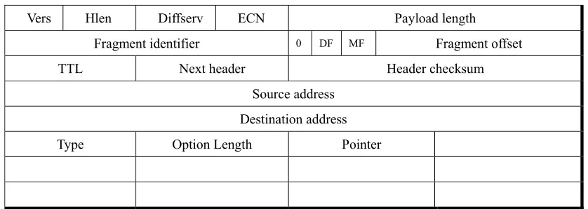
In Figure 2-1, we see the general form of the IP header. This form is widely used
in IP version 4. The detail of header entries is unnecessary for this paper, but the option
field at the bottom of the header is crucial part for the SDMM protocol. We will focus on
the option field in this section.
Figure 2-1. IP Header
Vers Hlen Diffserv ECN Payload length Fragment identifier 0 DF MF Fragment offset TTL Next header Header checksum
Source address Destination address
Type Option Length Pointer
The IP option is defined in the RFC 791 ‘Options’ section. It is optional and the
length varies depending on the option type. The ‘Head Length’ in IP header indicates the
total length of the header including the option field. Without the option field, a packet
8
60 bytes whereas 20 bytes is regular header size; the extra 40 bytes can be used for other
purposes. Reserving the space for an option code, length of option filed, and a pointer,
the option field can accommodate a maximum of 9 addresses.
Figure 2-2 shows standardized option type and its usage. However, not all of
them are commonly used today. The table includes the type value, the size, and an
indication of whether the option is copied into fragments of the original datagram. If a
router must fragment a datagram, those options that should be copied are placed in all
fragments. Options that are not copied are preserved in the datagram’s first fragment, but
not in others.
Figure 2-2. IP Options
Type Size Copied Use
0 1 byte No End of Options in Header
1 1 byte No Null Option
7 Varies No Record Route
68 Varies No Timestamp
82 12 bytes No Trace Route
130 11 bytes Yes Security Information
131 Varies Yes Loose Source Routing
136 4 bytes Yes Stream Identifier
137 Varies Yes Strict Source Routing
9
Each option begins with a byte that identifies the option type. If the option is
more than one byte in length, the next byte carries the size of the option data. This size
includes the option type byte and the option size, as well as the option data. The
remaining bytes of the option contain the actual option data. The end of option (0) and
null option (1) types are used for the systems to adjust the total size of the optional part of
an IP header. Since the IP Header Length field indicates size in units of four bytes, all IP
datagram must have a header size that is an even multiple of four bytes. If the total
header size does not meet these criteria, the system pad null options to the end of option
field to an appropriate size. The system can also add an end of options indicator, and the
rest of IP header is simply ignored.
Source Routing can be used as an example to explain the beginning part of the
SDMM protocol. In most of the normal cases, servers send out packets to the network
and leave the routing to the network itself. However, sometimes a server wants to control
the routing path. In this case, the Source Routing options give the server this control.
The server specifies the path a certain packet passes through, a requirement that is defined
by a subsequent routers’ addresses in the option field. The packet follows the path by
10 the packet to the next destination.
The pointer in the option field keeps track of the current position in the address list.
It points out the beginning byte of the next address. The pointer value is 4 initially,
because the fourth byte of the option contains the first address in the list. At each stop on
the list, the router adds 4 to this field, pointing it to the next destination in the list. When
this value exceeds the size of the options, no further source route processing is required,
and the packet makes its way to its destination.
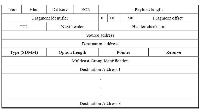
2.2.2. Option Header for SDMM
The header of the SDMM protocol is the same as the conventional IP header. It
has the 20-byte size of the regular header followed by the option field. Figure 2-3 shows
the general form of SDMM header. One minor difference from the regular IP header is
that the ‘Destination Address’ is not the final host address but the address of the MPLS
Label Edge Router (LER), where packets will be replicated and distributed. As
mentioned in the above section, Source Routing identifies the first router as destination
address; SDMM uses the same concept to guide a packet to the ingress node of MPLS
11 Figure 2-3. SDMM Header
Vers Hlen Diffserv ECN Payload length Fragment identifier 0 DF MF Fragment offset TTL Next header Header checksum
Source address Destination address
Type (SDMM) Option Length Pointer Reserve Multicast Group Identification
Destination Address 1 .
. .
Destination Address 8
Following the 20-byte regular header, the SDMM has an ‘Option Type’ in the IP
option field. This option type is 1 byte code, and the SDMM type code is written here.
An ‘Option Length’ defines the total length of the option field. Since the maximum
Header Length in regular header is 15, the maximum length of option field is 40 bytes.
The function of the pointer is the same as what is defined in the IP specification,
except that its initial value is 8 instead of 4. This is because the first 4 bytes after the
pointer and reserved byte are a Multicast Group Identification (MGI) number. The
destination addresses are written from the 8th byte (1st byte is 0) in the option field. The
12
Next, there is 1 byte of reserved space, which can be used in the future for traffic
engineering or other purposes. That issue, however, is for future study.
After the pointer and reserved byte, we have the Multicast Group Identification
(MGI). The MGI is necessary to identify the Forwarding Equivalence Class (FEC). We
define a FEC as a group that receives the same packets and that has the same source
address and MGI. For instance, if 30 users send requests for the same service to the
server in a certain period of time (5 seconds for example), and the server organizes those
30 users as one service group, they are a FEC in favor of SDMM. This definition is
useful only in explaining purpose and not for general terminology. The MGI is an
arbitrary number given by the server —we can use IP class D addresses or any numbers to
identify a FEC—and each different service group has different MGI. Consequently, the
header of one SDMM packet accommodates, at most, 8 destination addresses.
2.3.MPLS Multicast
2.3.1. MPLS (in general)
Conventional IP routing has drawbacks by nature. The routers need to lookup a
13
and general routing is carried out by software inside routers, conventional IP routing and
longest address matching cause significant delays from a sender to a receiver.
To address this drawback, several new routing ideas, including Gigabit/Terabit and
MPLS, have been introduced. A Gigabit/Terabit router increases the routing speed
significantly by adopting ASIC hardware technology. In contrast, MPLS is layer 3
switching protocol improving routing efficiency by separating routing (control plane) and
forwarding (data plane) procedure.
As control plane, the ingress node of Label Edge Router (LER) forwards a packet
to next hop following the conventional longest address matching algorithm—assuming
there is no traffic engineering involved—with label binding request (downstream demand
label binding) or without label binding request (downstream unsolicited label binding).
LSR, which forwarded the packet to its downstream, waits until label binding information
arrives from its downstream LSR. The labels are downstream-assigned and label
bindings are achieved from downstream to upstream. This procedure is a part of Label
Distribution Protocol (LDP), and it continues until the packet reaches an egress node of
MPLS domain. The egress LER binds a label with the FEC and notifies the bound label
14
upstream, and this process is continued until Label Switched Path (LSP) is established.
The label is a routing driver for MPLS. This label is located between the layer 3
and layer 2 header. Figure 2-4 shows the MPLS label format and its location. The total
length of label is 32 bits; 20 bits for label number, 3 bits for experimental, 1 bit for bottom
stack indicator, and 8 bits for TTL. LSR can insert multiple labels, called label stack.
Figure 2-4. MPLS Label Formats
Label CoS S TTL
20 bits 3 bits 1bit 8 bits CoS: Class of Service, S: Bottom of Stack, TTL: Time to Live
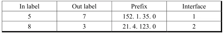
Figure 2-5. Label Information Base (example)
In label Out label Prefix Interface
5 7 152. 1. 35. 0 1
8 3 21. 4. 123. 0 2
After finishing the LSP setup, the data plane step occurs, which is actual packet
forwarding. Done with the LSP setup, each LSR has label binding information in its
Label Information Base (LIB). The LIB is a lookup table in which the entities are
15
FEC. When LSR receives a packet from upper LSR, it simply swaps the incoming label
with outgoing label to forward the packet to outgoing interface, instead of looking up the
routing table, which is time consuming.
When upstream LSR forwards a packet before it receives label bind information
from downstream LSR, upstream LSR simply forwards the packet to the next hop
following conventional IP routing protocol.
2.3.2. MPLS for SDMM
The initial SDMM packet sent to the ingress LER from the server has the purpose
of establishing a Label Switched Path (LSP), and it is replicated into multiple identical
packets. Each copied packet gets different destination addresses and the same multicast
group identity in its header. The FEC in SDMM is identified by source address and MGI
in the packet. If two packets have same source address and MGI in their header, we can
consider them to be the same FEC. The ingress node sends out each packet to the
downstream LSR, looking up the routing table. Default label binding is downstream
unsolicited.
16
it has a label matching with that FEC. If the LSR doesn’t have a label to match the FEC,
it creates new label and informs the upstream LSR, which is the case in independent label
binding, or it sends the packet to its downstream LSR again and waits until the label
binding information initiated from egress node reaches it, which is the case in ordered
label binding. If it already has the label bound to the FEC, the LSR simply forwards the
packet to the next LSR. However, if the LSR is the egress node of the LSP, it should
keep the destination address for that FEC in its LIB, even if it has the label bound for the
FEC. This destination address is necessary for swapping incoming label with final
destination addresses to forward a packet.
After communicating label binding to the upstream LSR, the egress node should
notify the server of its identity and destination addresses, which it takes care of. The
server uses this information later when it receives leave requests from the host. If one of
the multicasting members wants to leave the service, the server gets the address of the
egress router, which is the last LSR for that host, and sends a Leave Request directly to
that router.
If there are more destinations than one IP packet can accommodate (with SDMM,
17
packet(s) to the ingress LER. This additional packet adds more member(s) in a certain
FEC, and its form is same as the initial SDMM setup packet.
After final multicast tree establishment, the server sends data to the multicast group.
The receiving ingress node checks the packet to identify the group identity and source
address and then attaches a label header with the assigned label. The subsequent LSR
simply swaps the incoming label with outgoing label that was reserved for the FEC during
LSP setup stage before forwarding it to the next hop. Routing is done by regular MPLS
label switching and forwarding.
At the egress node, the label switching is different than conventional MPLS.
Instead of simple stripping off the label and sending the packet out of the MPLS domain,
the egress node in SDMM strips off the label, and gets the packet replicated by the number
of destinations the egress node has in its LIB for the FEC, and writes each destination
addresses to each packet before sending the packets to their destinations. Each packet
coming out from the MPLS domain should be routed by conventional IP routing protocol
18
2.4.Protocol Detail
2.4.1. Service Request
Let’s assume a demand for a server reaches its maximum capacity, and the delay
caused by overcapacity is intolerable. With conventional unicast, the server cannot
provide appropriate service at this time. Before getting worse, the server switches to the
SDMM protocol. With this SDMM, when the server receives a service request from a
user, it waits a certain period (tolerable amount of seconds) to gather multiple requests
from other users. When the waiting time ends (5 seconds, or 10 seconds for example),
the server aggregates the waiting requests.
The server keeps records of service groups in its database for management and
control purposes and provides the service for the members in the groups. Each packet
has the MGI and maximum of 8 destination addresses in the IP option header. Even
though one packet accommodates 8 hosts to maximum, every host addresses during a
certain period should have same MGI and be treated as the same FEC in the multicasting
perspective. The server sends SDMM LSP setup packets one by one until it uses up all
19
2.4.2. Ingress
The packets sent by the server are first destined to an MPLS edge router. This
router is an MPLS ingress node, and a packet is copied to multiple numbers of same
packets at this router. The ingress node realizes that packet’s destination is the node itself
and decides the next action by checking the option type (SDMM) of the header. It
identifies FEC by source address and MGI.
Each copied packet has a different destination addresses in its Destination Address
field but the same MGI to identify its FEC. The ingress node forwards the copied
packets to their destinations following the conventional longest address matching
algorithm. Until the ingress node receives the response for label binding from the
downstream LSR, it should forward subsequent FEC packets from the server by means of
conventional IP routing procedure.
2.4.3. MPLS Routing
The label binding is from downstream to upstream direction. The downstream
LSR, which receives initial SDMM packet from upstream LSR, chooses the outgoing label
20
information from the downstream LSR to its LIB and uses that label for subsequent packet
forwarding.
After the LSP is established, the following routing for the FEC is label switching to
LSRs. The process is simply swapping incoming label with outgoing label and
forwarding the packet to the outgoing interface.
In the egress node, the outgoing is not a label but an actual destination address for
the packet. The egress node removes the label header from the packet and writes the
destination address in IP header with the address that matches the incoming label. The
destination addresses for a label could be multiple—if a label has multiple destination
addresses in LIB of egress node, the egress node copies the packet to the multiple packets
with different destination addresses and then sends them to their destinations by means of
conventional IP routing.
2.4.4. Label Merge
LSR need not assign a new label for a FEC when it follows the same path. It uses
the same label for the FEC and simply ignores subsequent packets as long as they pass
21
In some cases, LSP for FEC overlaps at a certain LSR. When this happens, the
LSR merges two different labels into one, since two of them are the same FEC even
though they trace different paths until the LSR. LSR discards one of the two labels and
notifies the upstream LSR of the result. This reduces the overall traffic and label
consumption for upstream LSRs.
2.4.5. Add Request
If the server has more than 8 destinations for a FEC, it can send multiple SDMM
LSP setup packets to the ingress node until it uses up all destinations in the waiting list.
The subsequent SDMM LSP setup adds member requests for the FEC.
After established the LSP for a certain FEC, Add Requests for the FEC do not need
new label binding. The LSR, which receives the request from the upstream LSR or the
server, checks the source address and MGI to make sure same FEC is already registering
its LIB. If the LSR already has the label binding information in its LIB, it simply passes
the request to the next hop. If it doesn’t have a label for the FEC, the LSR chooses a new
label and sends the packet to the next hop with label binding request.
22
record of the destination address and its incoming label in its LIB. Egress node notifies
the adding result to the server with its IP address. As we mentioned already, this
information is necessary for the server to control and manage the multicasting group.
2.4.6. Leave Request
When one of users in a multicasting group wants to leave from the service, the
server sends Leave Requests directly to the egress node, which has the destination
addresses in its LIB for the user. The server knows the related information since the
egress notified it during LSP setup.
The egress node that receives the Leave Request discards the destination address
from the multicast group. If no members remain in the group after it discards the
destination, the egress notifies the upstream LSR that it doesn’t have any hosts to be
served for the FEC. This process is done recursively until it reaches the ingress node.
The upstream LSR that gets the notification removes the LSR from its LIB and discards
23
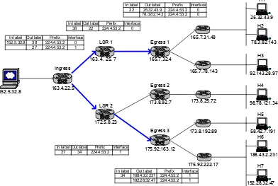
2.5. Example
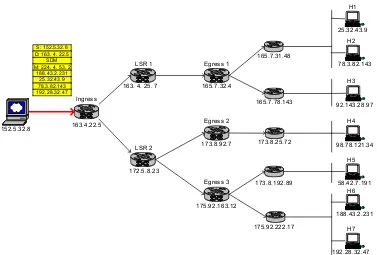
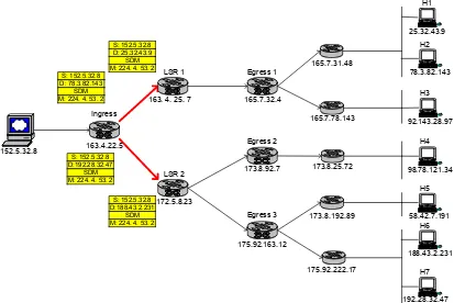
The example in this section may help to better understand the protocol. Figure
2-6 shows a model network for this example. This network has MPLS domain as well as
IP domain from a sender to destinations. Conventional IP routers can be located between
the server and MPLS ingress node, but those IP routers are omitted from the figure for the
sake of simplicity. Ingress, LSRs, and egresses are the routers in MPLS domain; the
remaining ones are IP routers.
Figure 2-6. Example Network Topology
S: 152.5.32.8 D: 163. 4. 22.5
SDM M: 224. 4. 53. 2
188.43.2.231 25.32.43.9 78.3.82.143 192.28.32.47 172.5.8.23 152.5.32.8 165.7.31.48 165.7.78.143 173.8.25.72 175.92.222.17 173.8.192.89 LSR 2 163.4.22.5 Ingress
24
2.5.1. Multicast Tree Establishment
Assuming that a server (152.5.32.8) in figure 2-6 receives the service requests from
4 hosts in a certain time period, it considers those 4 hosts to be a group. The server then
creates a packet for that group and writes all 4 destination addresses in IP option header to
establish a multicast tree for the group. This packet is a minimal size IP packet with an
option header to indicate its type (SDMM) and Multicast Group Identification. The
packet is sent to the ingress node for the multicast tree establishment, and this tree itself is
label switched path (LSP) in terms of MPLS.
The receiving ingress router checks the packet and tells that this packet is SDMM.
It replicates the packet as many times as the number of destination addresses in the option
header warrants—in this case, ingress copies 4 packets for the group. Replicated packets
are forwarded to the next routers following the conventional IP routing protocol. Figure
2-7 illustrates this. Again, since traffic engineering is not considered in this paper, the
forwarding is conducted by conventional IP routing which is the longest address matching
method.
Two packets—bound to H1 and H2—are forwarded to the LSR1, and the other two
25 Figure 2-7. Replicate Packet at Ingress Node
When LSR1 receives the first packet destined to H1 (25.32.43.9) from the ingress
node, it checks its label mapping table and realizes it doesn’t have a matching label entry
for that FEC. In case of independent label mapping, LSR1 picks a new label
immediately for that FEC and informs the ingress node of the label mapping information.
If label mapping, however, is in ordered mode, it forwards the packet downstream again.
Label binding is downstream assigned from egress node to the ingress node. Assuming
the LSRs agree on ordered and downstream unsolicited label mapping mode, the LSR1
forwards the packet destined for H1 to its downstream router, Egress1, again. Figure 2-8
S: 152.5.32.8 D: 78.3.82.143
SDM M: 224. 4. 53. 2
172.5.8.23 152.5.32.8 165.7.31.48 165.7.78.143 173.8.25.72 175.92.222.17 173.8.192.89 LSR 2 163.4.22.5 Ingress
163. 4. 25. 7 LSR 1 165.7.32.4 Egress 1 173.8.92.7 Egress 2 175.92.163.12 Egress 3 iMac 58.42.7.191 H5 iMac 188.43.2.231 H6 iMac 192.28.32.47 H7 iMac 98.78.121.34 H4 iMac 92.143.28.97 H3 iMac 78.3.82.143 H2 iMac 25.32.43.9 H1 S: 152.5.32.8 D: 25.32.43.9 SDM M: 224. 4. 53. 2
S: 152.5.32.8 D:188.43.2.231
SDM M: 224. 4. 53. 2 S: 152.5.32.8
26 explains this.
For the next packet bound to the H2, LSR1 checks its label mapping table again. In
this example, LSR1 hasn’t received label binding information from downstream after it
forwarded the packet destined to H1. Thus LSR1 simply forwards it to the next hop,
which happens to be the Egress1.
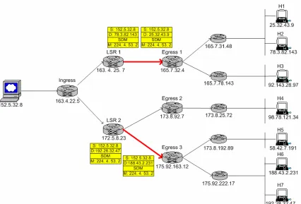
27
In Figure 2-9, two packets destined to H1 and H2 arrive at Egress1 contiguously.
When the first packet arrives, the Egress1 checks the FEC for the packet with its LIB and
finds it doesn’t have label entry for that FEC. It picks a new label and notifies the
upstream router, LSR1. Then, it keeps label mapping information in its LIB for future
label and destination address binding. In this example, Egress1 chooses label 22 for the
FEC. Additionally, egress node informs the server its label mapping result. This result
will be used for ‘member drop’ purpose later by the server.
Figure 2-9. Egress Node for LSP Establishment
S: 152.5.32.8 D: 78.3.82.143 DATA 172.5.8.23 152.5.32.8 165.7.31.48 165.7.78.143 173.8.25.72 175.92.222.17 173.8.192.89 Label reply Lab el reply
LSR 2 163.4.22.5
Ingress
163. 4. 25. 7 LSR 1 165.7.32.4 Egress 1 173.8.92.7 Egress 2 175.92.163.12 Egress 3 iMac 58.42.7.191 H5 iMac 188.43.2.231 H6 iMac 192.28.32.47 H7 iMac 98.78.121.34 H4 iMac 92.143.28.97 H3 iMac 78.3.82.143 H2 iMac 25.32.43.9 H1 S: 152.5.32.8 D: 25.32.43.9 DATA S: 152.5.32.8 D:188.43.2.231 DATA S: 152.5.32.8 D:192.28.32.47 DATA 22 34
In label Out label Prefix Interface 34 188.43.2.231 224.4.53.2 1
192.28.32.47 224.4.53.2 1 In label Out label Prefix Interface
28
When the second packet destined to H2 arrives at the Egress1 following the packet
for H1, Egress1 checks the source address and MGI in option header and realizes that it
already has the label entry for that FEC. Instead of creating new label, the Egress1
simply adds one more destination address for that FEC. However, it needs to transmit the
destination address information with its identity to the server for group management.
Now when Egress1 receives a packet from its upstream router and its label is 22, it
takes off the label and replicates the packet. It set the destination addresses with
addresses for H1 and H2 respectively before sending them out of MPLS domain.
Figure 2-10. Label Binding
172.5.8.23 152.5.32.8 165.7.31.48 165.7.78.143 173.8.25.72 175.92.222.17 173.8.192.89 Labe
l map ping Labe l m ap ping LSR 2 163.4.22.5 Ingress
163. 4. 25. 7 LSR 1 165.7.32.4 Egress 1 173.8.92.7 Egress 2 175.92.163.12 Egress 3 iMac 58.42.7.191 H5 iMac 188.43.2.231 H6 iMac 192.28.32.47 H7 iMac 98.78.121.34 H4 iMac 92.143.28.97 H3 iMac 78.3.82.143 H2 iMac 25.32.43.9 H1 38 27 In label Out label Prefix Interface 152.5.32.8 38 224.4.53.2 0
27 224.4.53.2 1
In label Out label Prefix Interface 38 22 224.4.53.2 0
In label Out label Prefix Interface 27 34 224.4.53.2 1
In label Out label Prefix Interface 34 188.43.2.231 224.4.53.2 1
192.28.32.47 224.4.53.2 1 In label Out label Prefix Interface
29
However, LSP establishment is not done yet, and the Egress1 does not receive a
packet with label 22. The LSP must be setup further.
After getting label mapping information from Egress1, LSR1 should choose its
own label for that FEC and informs its upstream node, Ingress. In Figure 2-10, LSR1
chooses 38 as the label for the FEC and notifies its label mapping to Ingress. Ingress
now has label 38 for the FEC from LSR1 and, in the same manner, it gets label 27 from
LSR2.
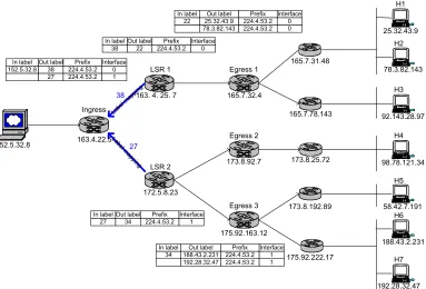
Figure 2-11. MPLS Multicast Tree
172.5.8.23 152.5.32.8 165.7.31.48 165.7.78.143 173.8.25.72 175.92.222.17 173.8.192.89 LSR 2 163.4.22.5 Ingress
163. 4. 25. 7 LSR 1 165.7.32.4 Egress 1 173.8.92.7 Egress 2 175.92.163.12 Egress 3 iMac 58.42.7.191 H5 iMac 188.43.2.231 H6 iMac 192.28.32.47 H7 iMac 98.78.121.34 H4 iMac 92.143.28.97 H3 iMac 78.3.82.143 H2 iMac 25.32.43.9 H1
In label Out label Prefix Interface 38 22 224.4.53.2 0
In label Out label Prefix Interface 27 34 224.4.53.2 1 In label Out label Prefix Interface
152.5.32.8 38 224.4.53.2 0 27 224.4.53.2 1
In label Out label Prefix Interface 34 188.43.2.231 224.4.53.2 1
192.28.32.47 224.4.53.2 1 In label Out label Prefix Interface
30
Figure 2-11 shows the LIB in each LSR and LSP for the multicast FEC after it
finishes the multicast tree (LSP) establishment step.
2.5.2. Multicast Data Routing
Figure 2-12. Send Data Packet to Ingress
With the given multicast tree, the server sends a packet for 4 destinations to the
Ingress LSR like Figure 2-12 illustrates. This packet is a regular IP packet except for the
172.5.8.23 152.5.32.8 165.7.31.48 165.7.78.143 173.8.25.72 175.92.222.17 173.8.192.89 LSR 2 163.4.22.5 Ingress
163. 4. 25. 7 LSR 1 165.7.32.4 Egress 1 173.8.92.7 Egress 2 175.92.163.12 Egress 3 iMac 58.42.7.191 H5 iMac 188.43.2.231 H6 iMac 192.28.32.47 H7 iMac 98.78.121.34 H4 iMac 92.143.28.97 H3 iMac 78.3.82.143 H2 iMac 25.32.43.9 H1
In label Out label Prefix Interface 152.5.32.8 38 224.4.53.2 0
27 224.4.53.2 1
S: 152.5.32.8 D: 163. 4. 22.5
SDM M: 224. 4. 53. 2
DATA
In label Out label Prefix Interface 38 22 224.4.53.2 0
In label Out label Prefix Interface 27 34 224.4.53.2 1
In label Out label Prefix Interface 34 188.43.2.231 224.4.53.2 1
192.28.32.47 224.4.53.2 1 In label Out label Prefix Interface
31
fact that it has option header to identify it for SDMM multicast; its multicast group
identification is 224.4.53.2. Ingress node, after getting the packet, looks up its LIB and,
seeing that it already has a label mapping entry matching for that FEC, then attaches the
label to that packet.
Since Ingress has two label mapping entries for the given FEC, it replicates the
packet and attaches label 38 to one of copy and label 27 to the other before forwarding
them to its downstream routers, LSR1 and LSR2. Figure 2-13 describes visual detail.
Figure 2-13. Multicast Forwarding at Ingress Node
172.5.8.23 152.5.32.8 165.7.31.48 165.7.78.143 173.8.25.72 175.92.222.17 173.8.192.89 LSR 2 163.4.22.5 Ingress
163. 4. 25. 7 LSR 1 165.7.32.4 Egress 1 173.8.92.7 Egress 2 175.92.163.12 Egress 3 iMac 58.42.7.191 H5 iMac 188.43.2.231 H6 iMac 192.28.32.47 H7 iMac 98.78.121.34 H4 iMac 92.143.28.97 H3 iMac 78.3.82.143 H2 iMac 25.32.43.9 H1
In label Out label Prefix Interface 152.5.32.8 38 224.4.53.2 0
27 224.4.53.2 1
27 S: 152.5.32.8 D: 163.4.22.5 SDM M: 224.4.53.2 DATA 38 S: 152.5.32.8 D: 163.4.22.5 SDM M: 224.4.53.2 DATA
In label Out label Prefix Interface 38 22 224.4.53.2 0
In label Out label Prefix Interface 27 34 224.4.53.2 1
In label Out label Prefix Interface 34 188.43.2.231 224.4.53.2 1
192.28.32.47 224.4.53.2 1 In label Out label Prefix Interface
32
Packet routing within interim LSR is simple label swapping, since the LSP
(multicast tree in this paper) is already established. The difference between SDMM and
ordinary MPLS forwarding is that, with SDMM, interim LSRs must replicate the packet
when an incoming label has multiple outgoing label mappings.
In Figure 2-13, LSR1 receives a packet from Ingress and has label 38, and it should
swap the label with label 22 before forwarding it to its outgoing interface. LSR2 does the
same jobs when it receives the SDMM packet from its upstream router. Label swapping
and forwarding is continued until the packet reaches at the egress node.
Figure 2-14. Multicast Forwarding at Interim LSR
172.5.8.23 152.5.32.8 165.7.31.48 165.7.78.143 173.8.25.72 175.92.222.17 173.8.192.89 LSR 2 163.4.22.5 Ingress
163. 4. 25. 7 LSR 1 165.7.32.4 Egress 1 173.8.92.7 Egress 2 175.92.163.12 Egress 3 iMac 58.42.7.191 H5 iMac 188.43.2.231 H6 iMac 192.28.32.47 H7 iMac 98.78.121.34 H4 iMac 92.143.28.97 H3 iMac 78.3.82.143 H2 iMac 25.32.43.9 H1
In label Out label Prefix Interface 152.5.32.8 38 224.4.53.2 0
27 224.4.53.2 1
34 S: 152.5.32.8 D: 163.4.22.5 SDM M: 224.4.53.2 DATA 22 S: 152.5.32.8 D: 163.4.22.5 SDM M: 224.4.53.2 DATA In label Out label Prefix Interface
38 22 224.4.53.2 0
In label Out label Prefix Interface 27 34 224.4.53.2 1
In label Out label Prefix Interface 34 188.43.2.231 224.4.53.2 1
192.28.32.47 224.4.53.2 1 In label Out label Prefix Interface
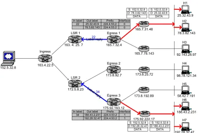
33 Figure 2-15. MPLS Forwarding at Egress Node
Figure 2-15 describes the packet forwarding at the egress node in MPLS domain.
Since the packet leaves the MPLS domain at egress node, the label, which has meaning
inside MPLS domain, should be stripped from the packet. The resulting packet is a
regular IP packet and has a final destination address which is from LIB in egress node.
From Figure 2-14 Egress1 receives a packet with label 22, and it checks its label
mapping table. From the label mapping table, the incoming label 22 should be switched
to two destination addresses, H1 and H2. Egress1 replicates the packet and writes the
172.5.8.23 152.5.32.8 165.7.31.48 165.7.78.143 173.8.25.72 175.92.222.17 173.8.192.89 LSR 2 163.4.22.5 Ingress
163. 4. 25. 7 LSR 1 165.7.32.4 Egress 1 173.8.92.7 Egress 2 175.92.163.12 Egress 3 iMac 58.42.7.191 H5 iMac 188.43.2.231 H6 iMac 192.28.32.47 H7 iMac 98.78.121.34 H4 iMac 92.143.28.97 H3 iMac 78.3.82.143 H2 iMac 25.32.43.9 H1
In label Out label Prefix Interface 152.5.32.8 38 224.4.53.2 0
27 224.4.53.2 1
S: 152.5.32.8 D:25.32.43.9 DATA S: 152.5.32.8 D:78.3.82.143 DATA S: 152.5.32.8 D:188.43.2.231 DATA S: 152.5.32.8 D:192.28.32.47 DATA In label Out label Prefix Interface
38 22 224.4.53.2 0
In label Out label Prefix Interface 27 34 224.4.53.2 1
In label Out label Prefix Interface 34 188.43.2.231 224.4.53.2 1
192.28.32.47 224.4.53.2 1 In label Out label Prefix Interface
34
destination address for each packet before sending them out to the next IP routers.
Remaining routing follows conventional IP routing.
2.5.3. Adding Member(s)
Adding a member or members to existing multicast group follows the same
procedure as the initial multicast tree establishment. Like Figure 2-16 depicts, the server
sends SDMM packet indicating group identification (MGI) in its option header to the
Ingress node. Two additional hosts H3 (92.143.28.97) and H4 (98.78.121.34) are
supposed to be added to multicast group 224.4.53.2.
Figure 2-16. Member Adding Request
172.5.8.23 152.5.32.8 165.7.31.48 165.7.78.143 173.8.25.72 175.92.222.17 173.8.192.89 LSR 2 163.4.22.5 Ingress
163. 4. 25. 7 LSR 1 165.7.32.4 Egress 1 173.8.92.7 Egress 2 175.92.163.12 Egress 3 iMac 58.42.7.191 H5 iMac 188.43.2.231 H6 iMac 192.28.32.47 H7 iMac 98.78.121.34 H4 iMac 92.143.28.97 H3 iMac 78.3.82.143 H2 iMac 25.32.43.9 H1
In label Out label Prefix Interface 152.5.32.8 38 224.4.53.2 0
27 224.4.53.2 1
S: 152.5.32.8 D: 163. 4. 22.5 SDM (Add) M: 224. 4. 53. 2
92.143.28.97 98.78.121.34
In label Out label Prefix Interface 38 22 224.4.53.2 0
In label Out label Prefix Interface 27 34 224.4.53.2 1
In label Out label Prefix Interface 34 188.43.2.231 224.4.53.2 1
192.28.32.47 224.4.53.2 1 In label Out label Prefix Interface
35
The ingress node does the same job as the initial tree establishment. It replicates
the packet if there are more than two destination addresses in the option header and
forwards them to the next routers in their destinations. LSR1 receives one packet and
LSR2 get the other in Figure 2-17.
Figure 2-17. Adding Member at Ingress Node
With the packet sent to the LSR1, LSR1 checks its LIB and knows that it already
has an entry for that FEC. Since the next hop for the packet is Egress1, which is the
36
However, when LSR2 receives a packet destined to the Egress2 as its next hop, LSR2
waits to label map until after it sends the packet to the next hop, which is a new path for
that FEC. These situations are described in Figure 2-18.
Figure 2-18. Adding Member at Interim LSR
Egress1 already has an entry for that FEC in its LIB, and it adds one more
destination address to that label entry. Egress1 informs the server and confirms adding a
membership. In other case, LSR2 sends the packet to Egress2 which is not an existing
37 label switching.
Figure 2-19. Multicast Tree after Adding Members
Figure 2-19 shows the label mapping information in all LSRs after adding two
members to the multicast group. Newly mapped label 45 is now in LSR2 and Egress2.
From now on, when LSR2 receives a packet that has label 27, it duplicates the packet as
38
2.5.4. Drop Member(s)
Some hosts might want send a leave request to the server in order to leave the
multicast service before the service ends. Since during the LSP setup stage, the egress
nodes inform the server of the membership status, the server knows which router is the
egress node for the leaving host. The server can directly send drop member request to
the egress node, and the egress node will remove the member from that multicast group.
Those procedures are Figure 2-20 through Figure 2-22.
39 Figure 2-21. Removing Member from LIB
After removing the member from the multicast group, Egress2 sends a label release
request to LSR2 because it has no member bound to that multicast group. Receiving the
label release request from the downstream router, LSR2 removes the label bound to
Egress2. If it does not have any member for that multicast group, LSR2 could send its
own label release request to the Ingress node. In this example it still has one member for
the group after releasing the label to the Egress2. Figure 2-22 shows the current status
40 Figure 2-22. After Removing Members
3. SDMM vs. IP Multicast
3.1. Source Control vs. Host Control
The drawback of IP multicast in the enterprise perspective is the lack of visibility
of entire multicast tree from the source. The source might want to know how many hosts
are linked to the multicast service and which hosts are currently connected to the tree.
With this information, the source can control the entire multicast tree and can charge a
41
However, the nature of IP multicast doesn’t give the source this amount of control
privilege. IP multicast is leaf initiated multicast; a host that knows the multicast address
for a certain service can connect to the multicast tree by sending ‘join’ request to its
nearest multicast router. The router receiving the ‘join’ request connects to its upstream
to establish multicast tree branch. This procedure is continued until the connection is
established between the source and the host.
Joining and leaving in IP multicast is the matter among routers or between a router
and a leaf host, therefore the source does not know the whole picture of the multicast tree.
Compare the IP multicast with SDMM protocol, in which the source itself
establishes and controls the multicast tree. The source manages the group membership
and adding and removing of a member from a group by sending request packet to relevant
router. Since the source initiates and manages multicast group, it does know the whole
multicast tree diagram and its membership status. This information is vital for the
commercial multicast network.
3.2. Multiple Group vs. Single Group
42
by the Internet Assigned Numbers Authority (IANA). Therefore usage is constrained and
limited. Usually the multicast address is single for a multicast service, so it is not easy to
differentiate the different service group for the service. For instance, when multiple hosts
request the service, their service environments are different. Some hosts use high speed
Internet, while other hosts use a slow modem connection for their internet service. Hosts
using a high speed network connection want to watch high resolution picture, while
modem users have to watch low resolution picture. Since IP multicast uses only one
multicast address for a service, it is not easy to differentiate between the different service
groups.
With SDMM, however, the MGI is an arbitrary and local number assigned by the
source. Therefore the assignment of group identification number is much more flexible
than in IP multicast, and the server can control a dynamically changing service group,
separating the group by access speed or resolution quality to satisfy for different demands.
3.3. Forwarding vs. Routing
Since SDMM adopts label switching technology as its routing protocol, the routing
43
multicasting, the interim LSR doesn’t need look up a routing table to forward the packet.
Instead, it simply switches the label of incoming packets before forwarding them to the
next hop. This reduces the delay caused by routing table lookup, which is the drawback
of Internet Protocol.
However, in the heterogeneous environment in which MPLS routers and IP routers
coexist, the overall efficient of multicasting is dependent upon the performance of IP
routers. Therefore, the advantage of adopting MPLS technology can be diluted unless all
paths from the source to the host are MPLS switching routers. Even though we cannot
derive the full advantage of MPLS until the environment is mature, SDMM still can
benefit from the flexibility of group management.
4. Simulation Analysis
4.1.Simulation Design
This simulation is for an hour with 8192 hosts and 8192 routers. For the sake of
simplicity, the overall network is connected as binary tree form with additional connection
between same level peers. At the end of the bottom routers in the tree, two hosts are
44
routers, however, for SDMM simulation, some routers from root to certain levels are
MPLS enabled routers, so called LSR (Label Switching Router). For the simulation
purpose, we change the number of LSRs in the network, but the ingress node is always the
root of the tree.
Each router has its address assigned from 1 to 8192 from top to bottom and from
left to right like a full binary tree. This simple IP address simplifies the routing
procedure, since a router just forwards the packet checking binary digit of destination
address. If a next bit from upper router chooses 0, forward the packet to left leaf,
otherwise forward it to the right.
A random number generator, known as Mersenne Twister, decides the time and
host number to which a host sends the service request. The service request is
exponentially distributed with a certain arrival rate. Arrival rate is varying for the
simulation purpose as well. The service duration for each host is a standard distribution
with 30 minutes as mean and 5 minutes as standard deviation. Once a host requests the
service, that host doesn’t send a request again during the simulation.
We want to see the change of server load as utilization and request drop ratio
45 by the window size and arrival ratio in SDMM.
4.2.Result and Analysis
4.2.1. Utilization of Server
Figure 4-1. Maximum Utilization (by Arrival Rate)
Maximum Utilization
(by Arrival Rate) Capacity: 1000 customers
0.0% 20.0% 40.0% 60.0% 80.0% 100.0% 120.0%
0.1 0.2 0.3 0.4 0.5 0.6 0.7 0.8 0.9 1 1.1 1.2 1.3 1.4 1.5
Customer Arrival Rate
Pe
rc
ent
a
g
e
IP SDMM
Figure 4-1 shows the comparison of the server utilization ratio in terms of
conventional IP and SDMM protocol. As the customer arrival ratio goes up, the
46
maximum capacity at 0.6 of the customer arrival ratio. After that, the server will reject
the service request. Those results are in the next section.
Compared to the IP protocol, the utilization ratio of the server with SDMM
protocol is stable between 20% and 40%. This is because, as the customer arrival ratio
goes up, the number of members in a multicasting group gets bigger. However, as you
will see later, even though the number of members in an FEC is getting bigger, the number
of FEC is not growing much. (We define FEC as same traffics that have the same MGI
as well as source address in SDMM flavor.)
Figure 4-2 is different perspective of the server utilization. As the server
capacity—measured as how many request the server can accommodate—gets bigger, the
utilization ratio of the SDMM protocol drops significantly while the utilization from IP
47 Figure 4-2. Maximum Utilization (by Capacity)
Maximum Utilization
(by capacity)
Customer Arrival Rate = 1.0
0.0% 20.0% 40.0% 60.0% 80.0% 100.0% 120.0%
200 300 400 500 600 700 800 900 1000 1100 1200 1300 1400 1500 1600 1700 1800 1900 2000
Capacity
Pe
rc
ent
a
g
e
IP SDMM
4.2.2. Request Drop Ratio
As mentioned above, when the server reaches its maximum capacity, it rejects the
service request. We measure this as Request Drop Ratio in Figure 4-3. Opposite to the
server utilization ratio, the Request Drop Ratio at a certain server capacity goes up when
the arrival ratio reaches 0.6 and then dramatically increases until it reaches the arrival ratio
48 Figure 4-3. Request Drop Rate (by Arrival Rate)
Request Drop Rate
(by Arrival rate)
Server Capacity = 1,000 customers
0.0% 10.0% 20.0% 30.0% 40.0% 50.0% 60.0% 70.0%
0.2 0.3 0.4 0.5 0.6 0.7 0.8 0.9 1 1.1 1.2 1.3 1.4 1.5 1.6 1.7 1.8 1.9
Arrival Rate
Pe
rce
n
t
IP SDMM
The request drop rate in terms of server capacity is decreasing as the server
capacity gets bigger, as we would expect. It is linearly proportional in IP protocol.
However, as we can see in Figure 4-3 and Figure 4-4, there is no drop in SDMM. This is
because SDMM is designed to aggregate the customers into a group to reduce the overall
data traffic in the network. The overhead caused by SDMM is an additional 8 bytes in
the IP option field (option code and MGI) during data transmission. We need a
maximum of 40 bytes in IP option field for 8 destination addresses maximum and
49
packets are only for LSP setup and the amount of the overhead is trivial comparing to the
size of data.
Because SDMM reduces the multiple redundant traffics with small portion of
giving overhead, the possibility of request drop is little. The drop ratio in this simulation
is zero, but considering the idealistic environment for the simulation, the real world
number is little worse than Figure 4-4. However, the bottom line in this result is that we
can improve the drop rate considerably with SDMM protocol.
Figure 4-4. Request Drop Rate (by Capacity)
Request Drop Rate
(by Capacity)
Customer Arrival Rate = 1.0
0.0% 10.0% 20.0% 30.0% 40.0% 50.0% 60.0% 70.0% 80.0% 90.0% 100.0%
100 200 300 400 500 600 700 800 900 1000 1100 1200 1300 1400 1500 1600 1700 1800 1900 2000
Capacity
Rat
e IP
50
4.2.3. Response Delay
The delay of response in IP protocol is short and constant as long as a host gets
response from the server. As the server receives the request, it immediately sends a
response to the host. Therefore, the delay is simply cased by the network other than the
server. However, in SDMM protocol, the delay of response is the average waiting time
the requests are in the waiting queue. The result of response delay in IP protocol has less
meaning since its request drop ratio is very high.
4.2.4. Number of FECs at Egress Node
The number of FECs at egress node and the number of destination addresses for an
FEC at an egress node are important factors in the implementation of SDMM since the
record in LIB of the egress node can be too long to handle if egress have to keep record of
so many destination addresses in its memory. Those are also a heavy burden to egress
node if it has to make too many copies for the all destinations when a multicast packet
comes out of the MPLS routers.
Figure 4-5 shows the number of FECs one egress node should have in its LIB for
51 gets long.
Obviously, the longer the LSP, the fewer the number of destination addresses an
egress node can see. As a reference, the average number of destination addresses for a
FEC an egress can follow is 6.2 when the server capacity is 1,000 customers and service
arrival rate is 1.0.
Figure 4-5. Number of FECs at Egress
Number of FECs at egress
(by length of LSP)
0 10 20 30 40 50 60 70 80 90 100
2 3 4 5 6 7 8 9 10
Length of LSP
Num
b
e
r
o
f
F
E
C
52
5. Future Study
In this paper, we used simplified network topology. However, the network in the
real world is not that simple and well organized. The real world network is a more
heterogeneous and more diverse environment. In future study of SDMM, we need
realistic environments for more accurate analysis.
In this paper, we use MPLS protocol as interim routers connecting the server to
destinations. However, we can apply this concept to the ATM switches also. ATM’s
VPI/VCI can be substituted by MPLS label and signaling to the LDP.
Also, IPv6 provides a different configuration for the network and gives more room
for IP option field. We will apply the SDMM concept to the other protocol including
IPv6. Additionally, if traffic engineering is involved, the taxonomy of the protocol is
more dynamic.
6. Conclusion
With SDMM protocol, we can use the given resources more efficiently. The
ingress and interim LSR reduce the redundant traffic using aggregating destination
53
a result, we can lower the utilization ratio significantly with SDMM and reduce the
possibility of request drop.
The major hurdle for the SDMM is the number of destination addresses which an
egress node takes care of. This could cause scalability problems. However, the
outcome number from simulation is not that big as long as the length of LSP is not too
short.
Some numbers from the result are idealistic. For instance, response delay is
almost constant even though the customer arrival rate gets high. This is because the
accurate relationship between each factor, and how much effect caused by one factor to the
other, is unknown. Unrealistic results come from those factors.
However, with same environment, we can compare two different protocols and
their reaction against a certain factor change. We collected all those data to compare two
different protocols, conventional Internet Protocol and suggesting Source Driven
54
Reference
[1] Thomas, Stephen A., “IP Switching and Routing Essentials”, John Wiley & Sons, Inc. [2] Chu, Yang-hua, et al. “A Case of End System Multicast”, In Proceedings of ACM
Sigmetrics, Santa Clara, CA, June 2000
[3] Pendarakis, Dimitrios, et al. “ALMI: An Application Level Multicast Infrastructure”, In Proceedings of USITS, March 2001
[4] Deering, S., "Host Extensions for IP Multicasting", STD 5, RFC 1112, Stanford University, August 1989
[5] Paul, Sanjoy, “Multicasting on the Internet And Its Application”, Kluwer Academic Publishers, 1998
[6] Rosen, E et al., “Multiprotocol Label Switching Architecture”, RFC 3031, January 2001
[7] Andersson L. et al, “LDP Specification”, RFC 3036, January 2001