STRUCTURAL BEHAVIOUR OF FIBER REINFORCED STEEL
CONCRETE COMPOSITE WALLS
Faezeh Faghih1, and Ashraf Ayoub2
1
Doctoral Candidate, Department of Civil Engineering, City University London, London, UK 2
Royal Academy of Engineering Pell Frischmann Chair of Nuclear Infrastructure, Department of Civil Engineering, City University London, London, UK
ABSTRACT
The addition of Steel Fibers (SF) to concrete has been widely studied in the past decades as a mean to control its crack behaviour and maintain its ductility in tension. It has been verified that the use of these fibers at an appropriate dosage can change the behaviour of structural members from brittle to ductile. Since the discovery of carbon nanotubes/fibers (CNT/CNF), they have been also considered as efficient fibers to be used in construction materials such as concrete. Previous experimental work has shown that incorporation of CNF in cementitious composites can enhance the mechanical behaviour of material by reducing the size of macro- and micro-cracks resulting in higher strength and ductility. In addition, due to tunnel conductivity effect, CNF concrete exhibits properties necessary for self-sensing and self-health monitoring ability.
This study aims to expand upon the use of SF and CNF concrete in structural members focusing on Steel Plate Composite (SC) systems currently used for safety-related structures. The use of both SF and CNF fiber reinforced concrete in SC systems could potentially be advantageous in many aspects such as performance enhancement of the structure under normal loading conditions as well as in case of hazard loads.
The study includes experimental tests to evaluate the performance of fiber-reinforced SC walls. A new finite element model to simulate SC structural members using fiber beam element is developed. The FE model is calibrated from the experimental tests and proved to provide satisfactory results.
INTRODUCTION
Concrete is a well-known construction material that has high compressive strength and low tensile strength. The behaviour of this material has been studied for better properties and many new forms of this material has been developed and introduced to the industry namely Lightweight concrete, fiber reinforced concrete, Ultra-high performance concrete, Reactive powder concrete. The most common and well researched material is fibre reinforced concrete using different fibers. The concept of using fibers is to enhance the tensile behaviour of the concrete by bridging the cracks and improving the load carrying capacity of the structural members. Concrete properties exist in multiple length scales of nano, micro and macro sizes and the properties of each scale is derived from those of the next smaller scale.
while carbon nanofibers are made of stacked cone shapes which have exposed edge planes along their surfaces.
Table 1: Properties of Carbon Nanotubes and Carbon Nanofibers
Material type
Typical Characteristics
Physical Properties Mechanical Properties
Typical Cost ($)/g
Diameter Length Young’s
Modulus
Tensile Strength
CNT SWCNT 0.3-2 nm >200 nm 1 TPa 60 GPa ~$180
*
MWCNT 20-40 nm 1-20 μm ~$82*
CNF 60-150 nm 30-100 μm 400 GPa 7 GPa ~ $0.55**
*
Thomas Swan & Co. Ltd – Elicarb (R) **
Applied Science, Inc – Pyrograf Products
Figure 1. Schematic illustration of CNT and CNFs: (a) Single-wall carbon nanotube; (b) Multi-wall carbon nanotube; and (c) structure of a nano-cone-stacked CNF
To date, the research on nano fibers have mainly been focused on the cement paste and it is concluded that the properties of the cement paste can be enhanced by increased compressive strength, lower thermal conductivity, increased durability, and increased electrical conductivity for health monitoring purposes (Metaxa et al. 2013, Hunashyal et al. 2011, Yazdanbakhsh and Grasley, 2011).
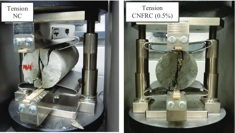
An initial material test is conducted on CNFRC with 0.5% of fibers by volume of the binder. The CNF is mixed with water and superplasticiser and then sonication techniques are used to properly disperse it. Compression and split tensile tests were conducted on cylinders of H200×D100 mm and the strength of the material is derived and compared to normal concrete. Table 2 and Figure 2 below show the results of the test.
Table 2: Comparison of results for NC and CNFRC
% CNF by volume of
the binder
w/c Compressive strength (MPa)
Split tensile strength (MPa)
Normal Concrete 0 0.34 60.5 6.2
CNFRC 0.5 0.34 84.0 6.7
Figure 2. Experimental results after the test
The results of this simple comparison show that concrete with similar proportions and constituents has higher strength under compression by 38.8% and the split tensile strength is increased by 8%. Further tests are being conducted to evaluate the ductility enhancement of the concrete by using such fibers in the concrete.
For this research study the type of structural member to be investigated is known as Steel Concrete sandwich wall, which is used for heavy structures. Steel Concrete composite (SC) construction is a sandwich system in which two steel plates encase the concrete in the middle. The composite action is provided by the shear studs. The SC system was originally devised for use in submerged tube tunnels over 25 years ago and it is used for high rise building core wall, power plants and offshore structures. SC enables the building to maintain a highly seismic condition. Figure 3 shows the composition of this sandwich system.
Figure 3. SC system (Wright and Oduyemi, 1991)
In this study the element developed by Mullapudi and Ayoub (2010) in the general finite element programme FEAPpv (Taylor, 2012) is used, and material models of steel fiber reinforced concrete and carbon nanofiber reinforced concrete is validated against experimental results to be used for performance analysis of SC walls. The results of this finite element study provide more information to help understand the behaviour of CNF concrete and its effect on structural members such as SC wall.
Compression Compression Tension
NC
FINITE ELEMENT MODEL
Constitutive models describing the behaviour of the material is critical in the finite element modelling of structural members. In this study, the fiber beam element is used which is a shear-based fiber beam-column element with distributed inelasticity that was developed by Mullapudi and Ayoub (2010). They adopted the Softened membrane model (SMM) model, which was developed by Zhu et al. (2002) and is capable of predicting the entire monotonic response of the load-deformation curves including the ascending and descending branches. Also the Timoshenko beam theory was considered in this beam element to account for shear deformation effect.
CORRELATION WITH EXPERIMENT
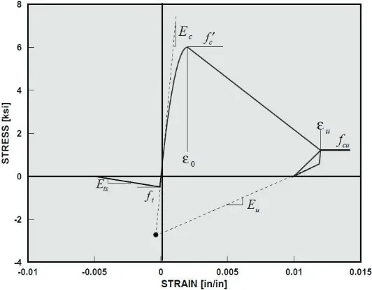
The constitutive material model and key parameters which represent the material behaviour are defined in the programme for the concrete as shown in Figure 4. In fiber reinforced concrete the cracked concrete can still initially carry some tensile stresses in the direction normal to the crack known as tension-stiffening. Tension-stiffening effect is considered to describe the post cracking response of concrete. This value varies for different fibers as they perform differently based on the effectiveness of the fibers on the material properties.
Figure 4. Typical concrete stress-strain diagram
applied. The results of the model and experimental test are shown in Figure 6. A good correlation is observed for the case with 1% steel fiber.
Figure 5. Beam A11 geometry (all dimensions in mm)
Figure 6. Load – Deflection Curves (A11)
Another material is Reactive Powder Concrete (RPC) which has a very high compressive material and it uses steel fibers to enhance the brittle behaviour of the concrete. Beam R13 tested by Yang et al. (2010) had dimensions as follows: a beam width of 180 mm, a beam height of 270 mm, over a span of 2900 mm. One rebar layer arranged in three rows was designed with nominal diameter of 13 mm. Steel fibers were used with the volume fraction of 2% and no transverse reinforcement was used. Figure 7 shows the comparison of the analysis and the experimental results and good correlation is observed hence the material properties are verified.
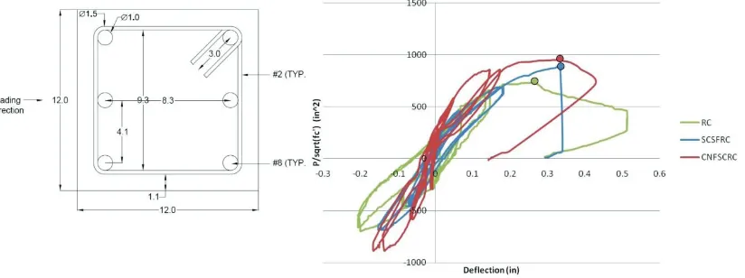
The effect of carbon nanofiber reinforced concrete with 1% of fibers was studied on the cyclic behaviour of the short shear-critical column by Howser (2010). The column was 20 (inch) in height with a 12 (inch) square crossǦsection. The reinforcement contained six #8 longitudinal rebars and #2 stirrups with a spacing of 4.75 (inch) providing transverse reinforcement (See Figure 8). The column was rigidly connected to a concrete foundation. An axial load equal to oneǦtenth of the column’s axial
capacity (87.4 kips) was applied followed by a lateral reversedǦcyclic load at the top of the column 0
50 100 150 200 250
0 10 20 30
L
o
a
d
(
k
N)
Deflection (mm)
Experiment-A11
until failure occurred. The results of the behaviour of the column with reinforced concrete (RC), Steel fiber reinforced concrete (SCSFRC) and CNF concrete (CNFSCRC) is shown in Figure 8.
Figure 7. Load-Deflection Curve for RPC
The column was modelled using the fiber beam element with the cross section of the element divided into 12 longitudinal fibers, and the load was applied to obtain the backbone curve of the cyclic behaviour. The result of the FE analysis and monotonic behaviour of the specimen is presented in Figure 9.
Figure 8. Left: cross section of column (all dimensions in inches), Right: load-deflection behaviour of columns (Howser, 2010)
To evaluate the behaviour of SC walls, they were first modelled and validated in FEAPpv. The specimen tested by Varma et al. (2011), was chosen for the purpose of this study. The specimen (SP1-5) represented full scale geometric dimensions in terms of what is used in the current SC construction (Figure 10). It should be noted that the FE model takes into account the vertical shear resistance by assuming smeared reinforcement.
0 20 40 60 80 100 120 140 160 180 200
0 5 10 15 20 25 30 35
L
o
ad
(
k
N)
Midspan Deflection (mm)
Figure 9. Load-Displacement behaviour of SCCNFC column
Figure 10. Specimen geometry and concrete crack map for SP1-5 (Varma et al., 2011)
Figure 11 shows a comparison of the experimentally measured and analytically predicted load-displacement responses for Specimen SP1-5.
Figure 11. Experimental vs. FE results for SP1-5 0
50 100 150 200 250
0 0.5 1 1.5 2
Lo
ad
(
K
ips
)
Deflection (inch)
SP1-5
Experiment
FE 0
10 20 30 40 50 60 70 80
0 0.1 0.2 0.3 0.4 0.5
Load
(Ki
ps
)
Displacment (inch)
Experiment
STRUCTURAL BEHAVIOUR OF STEEL COMPOSITE WALL
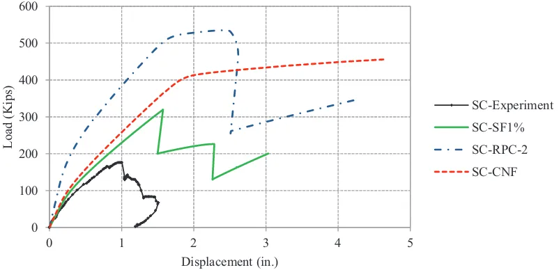
The behaviour of the SC element using the validated FE model of SC was analysed using properties of previously validated materials; steel fiber reinforced concrete (Vf =1%), RPC and CNF reinforced concrete. The graphs representing SC beam element with incorporation of each material is presented in Figure 12 and Table 3.
The CNF concrete with only 1% volume of fibers increased the loading capacity by more than 158% and showed the most ductile behaviour amongst other materials (Ductility>2). From the post peak behaviour it is apparent that the behaviour of the SC member is transformed from brittle to very ductile. It should be noted that ductility is of an importance to enhance structural behaviour under both monotonic and cyclic loads and prevent premature failure of members and according to this results, the CNF reinforced concrete can highly enhance the structural behaviour of the member, and is thus considered a great fiber to be used in concrete as opposed to steel fiber.
Figure 12. FE analysis of SC element with different materials
Table 3: Performance of SC beam with smart materials. 0
100 200 300 400 500 600
0 1 2 3 4 5
L
o
ad
(
Kips)
Displacement (in.)
SC-Experiment SC-SF1% SC-RPC-2 SC-CNF
Properties SC (Test)
SC
(FE) SC-SF1% SC-RPC-2 SC-CNF
ܲ௨ [kips]
Ultimate Load 177 193 319 535.2 >456.2
݀௨ [in]
Displacement at ultimate load
1.0 1.0 1.57 2.44 >4.5
µ
Ductility 0 0 0 ~1.53 >2
K [kips/in]
Initial stiffness 390 311 374.8 829.6 427.8 Enhance
ment
ܲ௨ - - 80.2% 202.4% >157.7%
CONCLUSION
Amongst the different developed concrete materials, steel fiber is the one mostly studied by researchers. Amongst newly discovered fibers the CNF has gained more attention in the world of nanotechnology and it is being studied extensively for the past few years. However, the study on CNF concrete is limited to the material level and is mainly focused on cement mortar paste. A material test on CNF mortar has shown that the addition of such fibers increases the compressive and flexural strength of the mortar. In this study, CNF is considered in the concrete and it was evident that the addition of 0.5% fibers improved the mechanical properties of the concrete. There is a gap in finding the effect of CNF concrete at the structural level, which in this study was analysed using the general purpose Finite Element Programme FEAPpv. The results showed that CNF concrete enhances the cyclic behaviour of the structural members as well as the strength, ductility and energy absorption of the member under load. The performance of SC walls proved to be better when CNF concrete is used compared to steel fiber reinforced concrete.
REFERENCES
Cucchiara C., Mendola, L.L., and Papia, M. (2004), “Effectiveness of stirrups and steel fibers as shear
reinforcement,” Cement and Concrete Composites, No. 26, pp. 777-786.
Howser, R. (2010), Behavior of Steel Fibers and Crabon Nanofibers in Shear-Critical Reinforced Concrete Columns, MS Thesis, Department of Civil engineering, University of Houston, State of Texas.
Hunashyal, A. M., Tippa, S. V., Quadri, S. S., and Banapurmath, N. R., (2011) Experimental Investigation on Effect of Carbon Nanotubes and Carbon Fibres on the Behavior of Plain Cement Mortar Composite Round Bars under Direct Tension, International Scholarly Research Network ISRN Nanotechnology, Article ID: 856849.
Metaxa, Z. S., Konsta-Gdutous, M. S., and Shah, S. P., (2013). “Carbon nanofiber cementitious
composites-effects of debulking procedure on dispersion and reinforcing efficiency”, Cement and Concrete Composites, 36: 25-32.
Mullapudi, T.R., and Ayoub, A. (2010), “Modelling of the seismic behavior of shear-critical
reinforced concrete columns”, Engineering Structures. 32: 3601-3615.
Taylor, R. L. (2012), FEAPpv User Manual v.3.1. Department of Civil and Environmental Engineering, University of California, Berkeley.
Varma, A. H., Malushte, S. R., Sener, K. C., Boot, P. N., and Coogler, K. (2011) STEEL-PLATE COMPOSITE (SC) WALLS: ANALYSIS AND DESIGN INCLUDING THERMAL EFFECTS Transactions, SMiRT 21, New Delhi, India,6-11 November, Paper No. 761.
Wright, H.D., Oduyemi, T.O.S., Evans, H.R., (1991) The Experimental Behaviour of Double Skin Composite Elements, J. Construct. Steel Research, 19: 97-110.
Yang, I.H., Joh, C., and Kim, B.S., (2010). “Structural behaviour of ultra-high performance concrete
beam subjected to bending,” Engineering Structures, No. 32, pp. 3478-3487.
Yazdanbakhsh, A., Grasley, Z., Tyson, B., and Abu Al-Rub, R. A., (2010a). “Distribution of Carbon Nanofibers and Nanotubes in Cementitious Composites.” Journal of the Transportation Research Board, Transportation Research Board of the National Academies, Washington, 2142: 89–95.