University of Windsor University of Windsor
Scholarship at UWindsor
Scholarship at UWindsor
Electronic Theses and Dissertations Theses, Dissertations, and Major Papers
2017
Security Enhancement for ZigBee and Bluetooth
Security Enhancement for ZigBee and Bluetooth
Chen Chen
University of Windsor
Follow this and additional works at: https://scholar.uwindsor.ca/etd
Recommended Citation Recommended Citation
Chen, Chen, "Security Enhancement for ZigBee and Bluetooth" (2017). Electronic Theses and Dissertations. 5973.
https://scholar.uwindsor.ca/etd/5973
This online database contains the full-text of PhD dissertations and Masters’ theses of University of Windsor students from 1954 forward. These documents are made available for personal study and research purposes only, in accordance with the Canadian Copyright Act and the Creative Commons license—CC BY-NC-ND (Attribution, Non-Commercial, No Derivative Works). Under this license, works must always be attributed to the copyright holder (original author), cannot be used for any commercial purposes, and may not be altered. Any other use would require the permission of the copyright holder. Students may inquire about withdrawing their dissertation and/or thesis from this database. For additional inquiries, please contact the repository administrator via email
Security Enhancement for ZigBee and Bluetooth
by
Chen Chen
A Thesis
Submitted to the Faculty of Graduate Studies
through Electrical and Computer Engineering
in Partial Fulfilment of the Requirements for
the Degree of Master of Applied Science at the
University of Windsor
Windsor, Ontario, Canada
2017
c
Security Enhancement for ZigBee and Bluetooth
by
Chen Chen
APPROVED BY:
J. Chen
School of Computer Science
H. Kwan
Department of Electrical and Computer Engineering
H.Wu, Advisor
Department of Electrical and Computer Engineering
AUTHOR’S DECLARATION OF ORIGINALITY
I hereby certify that I am the sole author of this thesis and that no part of this
thesis has been published or submitted for publication.
I certify that, to the best of my knowledge, my thesis does not infringe upon
anyones copyright nor violate any proprietary rights and that any ideas, techniques,
quotations, or any other material from the work of other people included in my
thesis, published or otherwise, are fully acknowledged in accordance with the standard
referencing practices. Furthermore, to the extent that I have included copyrighted
material that surpasses the bounds of fair dealing within the meaning of the Canada
Copyright Act, I certify that I have obtained a written permission from the copyright
owner(s) to include such material(s) in my thesis and have included copies of such
copyright clearances to my appendix.
I declare that this is a true copy of my thesis, including any final revisions, as
approved by my thesis committee and the Graduate Studies office, and that this thesis
ABSTRACT
With the development of wireless technology, the social daily life has an increasing
relationship with the wireless networks and the issue of wireless network security has
caught more and more attention. In this thesis, two new protocols for ZigBee security
are proposed. For the first time public key technology has been used to enhance
the security strength for ZigBee master key establishment. The proposed protocols
strengthened ZigBee master key establishment security, which subsequently secure the
establishment of the network key and link key, both derived from the master key. By
integrating unbalanced RSA into the key establishment protocols, the new methods
can distribute different computation amount to the ZigBee devices in communication
based on their computational capacities.
An efficient key establishment protocol for Bluetooth is proposed. It also utilizes
public key technology to avoid the involvement of a third party and to improve the
security strength. This proposed work requires fewer protocol steps and is thus faster
DEDICATION
To my loving parents:
Father: Li Ming
ACKNOWLEDGEMENTS
I would like to express my sincere gratitude and appreciation to everyone who
helped make this thesis possible. First of all, I would appreciate my parents. Their
support encouraged me to overcome all difficulties that I met during my study. They
supported me to study aboard and gave me financial support, without whom, I could
not achieve my study. Also, I am deeply indebted to my supervisor Dr.H.Wu,
pro-fessor of Electrical and Computer Engineering at University of Windsor, for guiding
me throughout the writing of this thesis. As one of best teachers I have ever had,
Dr.H.Wu impressed upon me that a good teacher instructs students in matters far
beyond those in textbooks. His broad knowledge and logical way of thinking have
been of great value; without his detailed and constructive comments on my research,
none of this thesis would be possible.
from the School of Computer Science also gave me a lot of help. He read through
my thesis page by page and gave me advice about how to use words in technical
writing. I really appreciate it.
I would also grateful to my colleagues and friends, Ruiqing Dong, Huyuan Li,
Bingxin Liu,Chunyu Mao and Siyu Zhang who gave me their help and time in listening
to me and helping me work out my problems during the difficult course of the thesis.
Finally, I wish to extend my gratitude to the faculties of Electrical and Computer
Engineering at University of Windsor for their efforts and help during my study for
the master degree. Moreover, my thanks would go to the financial support from the
University of Windsor and my supervisor Dr.H.Wu.
TABLE OF CONTENTS
AUTHOR’S DECLARATION OF ORIGINALITY iii
ABSTRACT iv
DEDICATION v
ACKNOWLEDGEMENTS vi
LIST OF TABLES x
LIST OF FIGURES xi
LIST OF ACRONYMS xii
1 INTRODUCTION 1
1.1 Research Motivation . . . 2
1.2 Research Contributions . . . 2
1.3 The Scope and Organization of the Thesis . . . 3
2 TECHNICAL BACKGROUNDS 4 2.1 ZigBee System and Security . . . 4
2.1.1 ZigBee Network System Devices . . . 4
2.1.2 Three Kinds of ZigBee Network Topologies . . . 6
2.2 Bluetooth and its Security . . . 8
2.3 RSA and Unbalanced RSA . . . 9
2.3.1 Development of RSA and Unbalanced RSA . . . 10
2.3.2 RSA Algorithm . . . 11
2.4 Security Strength and Requirements . . . 14
2.4.1 Security Strength of Key Length . . . 14
2.4.2 Lightweight and Ultra-lightweight Security . . . 15
2.5 Comparison Between RSA and Unbalanced RSA . . . 15
2.5.1 Reasons of Choosing Unbalanced RSA . . . 16
3 AN OVERVIEW OF RELATED WORKS 17 3.1 Security Options for ZigBee and Bluetooth Standards . . . 17
3.2 Key Structure in ZigBee and Bluetooth . . . 18
3.3 On Confidentiality in ZigBee and Bluetooth . . . 19
3.4 On ZigBee Authentication . . . 20
3.4.1 Certificate Authenticaion . . . 20
3.4.2 Message Authentication Code . . . 23
3.4.3 Network Key Authentication . . . 27
3.5 Existing Works on ZigBee Key Management . . . 28
3.5.1 Group key protocols . . . 28
3.5.2 Symmetric Key Establishments . . . 30
3.5.3 Pre-installed Master Key . . . 31
3.5.4 User-entered Master Key . . . 32
3.5.5 Key-transport Master Key . . . 32
3.6 Recent Works on Bluetooth Security . . . 33
3.6.1 Initialization Key Transmission . . . 33
3.6.2 Unit Key Transmission . . . 34
3.6.3 Combination Key Transmission . . . 35
3.6.4 Master Key Transmission . . . 36
3.6.5 Diffie-Hellman Scheme . . . 37
3.6.6 Unbalanced RSA Protocol . . . 38
3.6.8 Challenge-response Scheme . . . 40
4 PROPOSED WORKS 42
4.1 New Master Key Establishment Protocol in ZigBee . . . 42
4.2 Simplify Master Key Establishment Security Protocol in ZigBee . . . 43
4.3 Simulation Results for RSA and Unbalanced RSA Algorithms . . . . 45
4.3.1 Simulation Results . . . 45
4.3.2 Analysis of Results . . . 47
4.4 Enhancement for the Unbalanced RSA Algorithm in Bluetooth . . . . 48
5 CONCLUSIONS AND FUTURE WORKS 50
5.1 Conclusions . . . 50
5.2 Possible Future Work . . . 50
REFERENCES 51
LIST OF TABLES
2.1 Relationship of Security level and RSA modulus size . . . 14
2.2 Comparison between RSA and unbalanced RSA . . . 15
3.1 Notation and Abbreviation in MAC . . . 24
4.1 Simulation Results for 1024 bits of the RSA and unbalanced RSA
al-gorithms . . . 46
4.2 Simulation Results for 2048 bits of the RSA and unbalanced RSA
LIST OF FIGURES
2.1 Star Topology in ZigBee system[1] . . . 6
2.2 Cluster tree Topology in ZigBee system[2] . . . 7
2.3 Mesh Topology in ZigBee system[1] . . . 8
2.4 Topology in Bluetooth system[3] . . . 9
3.1 Security in ZigBee and Bluetooth stack[4] . . . 20
3.2 Authentication protocol between TC and MCA . . . 21
3.3 Authentication protocol between TC and MED through MCA . . . . 21
3.4 MAC Authentication Protocol . . . 24
3.5 Network key authentication . . . 27
3.6 Group key protocol . . . 29
3.7 Symmetric key protocol . . . 30
3.8 Initialization key transmission protocol . . . 33
3.9 Unit key transmission protocol . . . 35
3.10 Combination key transmission protocol . . . 35
3.11 Master key transmission protocol . . . 36
3.12 Diffie-Hellman scheme . . . 37
3.13 Key establishment protocol in Bluetooth using unbalanced RSA . . . 39
3.14 Challenge-response scheme protocol . . . 40
4.1 Master key establishment protocol by unbalanced RSA algorithm . . 42
4.2 Improvement master key establishment protocol by unbalanced RSA algorithm . . . 44
LIST OF ACRONYMS
ACE active constellation extension
ADC analog to digital convertor
ADSL asymmetric digital subscriber line
API average power increase
BER bit error rate
CC computational complexity
CCDF complementary cumulative distribution function
CDMA code-division multiple access
CP cyclic prefix
DAB digital audio broadcasting
DFT discrete fourier transform
DIF differential item functioning
DRL data rate loss
DSP digital signal processing
DVB digital video broadcasting
FFT fast fourier transform
GI guard interval
HDSL high-bit-rate digital subcriber line
ICI inter-carrier interference
IDFT inverse discrete fourier transform
IFFT inverse fast fourier transform
ISI inter-symbol interference
LO local oscillator
LTE long term evolution
MC multi-carriers
OBR out-of-band radiation
OFDM orthogonal frequency division multiplexing
PAPR peak to average power ratio
PBISLM partial bit inverted SLM
PPPW-SLM partitioning and partial-phase-weighting-SLM
PRC PAPR reduction capabilitiy
PRT peak reduction tone
PTS orthogonal frequency division multiple access
PTS partial transmit sequence
PTS partial transmit sequence
QAM quadrature amplitude modulation
QPSK quadrature phase shift keying
RMS root mean square
SC single-carrier
SC-FDMA single carrier frequency division multiple access
SI side information
SLM selected mapping
SNR signal-to-noise ratio
SSPA solid state power amplifier
TI tone injection
TPPW-SLM time-domain-partial-phase-weighting-SLM
TR tone resercation
TWTA traveling wave tube amplifier
VC variance of correlation
WLAN wireless local area networks
1
INTRODUCTION
The Internet of Things (IoT) is the inter-networking of different physical devices and
objects embedded with sensors, electronics, and even software, which reflects the
constant development of the Internet from human to things since 1999 when the idea
of combination of the RFID technology with sensor technology to set up a IoT was
first proposed [5]. After this, IoT has received increasingly fast development in recent
years to include wireless standards, i.e., WiFi, Bluetooth, and ZigBee, as its main
networking technologies.
Bluetooth wireless technology was proposed in 1997 [5] and later standardized in
IEEE 802.15.1 [6]. This networking technology provides easy wireless connection
be-tween devices in short distance, i.e., up to 10 meters, and with the bandwidth enabling
transmission of audio, still image, and control signals. Bluetooth technology is very
popular both in office and home environmental for pairing computer, phone, speaker,
camera, printer, fitness equipment, etc. The concern on its security is receiving more
and more attention due to its increasingly popular and wide uses in IoT.
ZigBee technology was first proposed in 1998 [7], one year later than Bluetooth.
ZigBee provides wireless networking with greater distance and lower bandwidth and
power consumption, compared to Bluetooth. ZigBee is very popular in IoT for smart
home and healthcare applications. This technology is standardized by IEEE in 2003
as in 802.15.4 [7]. When used for healthcare for transmission of a patient’s private
medical data, its security requirement and implementation is highly anticipated. Due
to the fact that very simple devices are often used in a ZigBee network, any security
consideration for these simple devices has to be with low computation complexity and
1.1
Research Motivation
ZigBee and Bluetooth technologies have wide applications in IoT, especially in smart
office, smart home and smart healthcare, where data, often of a confidential nature,
are transmitted over the wireless network. On the other hand, there are a number of
security attacks that pose threats to the transmitted confidential data, for example,
eavesdropping, impersonating, signal jamming, and violation of data integrity [8].
Eavesdropping is a scenario that an attacker secretly listening to the private
con-versation of others without their consent [8]. A security service called confidentiality
is often employed to safeguard private data from eavesdropping attack. If a malicious
third party attempts to illegally modify the transmitted data between the sender and
the receiver, it is a case of violation of data integrity [9]. Impersonating is an very
common threat that an attacker impersonates a legitimate user to send or receive
data [9]. To prevent the system from either violation of data integrity attack or
impersonating attack, we need the security service of authentication [10].
In order to provide security services like confidentiality and authentication, a
security system must implement certain secure and efficient key establishment scheme
to facilitate the subsequent encryption/decryption and/or authentication process. In
this thesis, we focus on the research work on secure and efficient key establishment
for ZigBee and Bluetooth systems.
1.2
Research Contributions
Research works and contributions in this thesis include two new ZigBee master key
establishment protocols with enhanced security and one efficient key establishment
protocol for Bluetooth.
• Proposed ZigBee master key establishment protocol with enhanced security
the first time that public key technology has been proposed for ZigBee master
key establishment. The protocol not only implements key distribution between
ZigBee parties but also provides strong authentication service to thwart possible
impersonating attack.
• The second proposed ZigBee key establishment protocol is a modified version
of the first one by trimming the authentication steps in the protocol. This
simplified version is faster than the first one and suitable for being used between
the authenticated ZigBee devices.
• A fast Bluetooth key establishment protocol is proposed, which is requires fewer
protocol steps without sacrificing the security strength, compared to the similar
work in [11].
1.3
The Scope and Organization of the Thesis
An organization of the rest of the thesis is as follows: in Chapter 2, the ZigBee and
Bluetooth technologies will be discussed and their security requirements and public
key cryptographic system RSA are reviewed. A modified version of RSA, unbalanced
RSA is also introduced in this chapter. Then, the Chapter 3 will give an overview of
the related existing works.New key establishment protocols are proposed in Chapter
4, along with the simulation results. Finally, Chapter 5 will provide the possible
2
TECHNICAL BACKGROUNDS
In this chapter, the ZigBee and Bluetooth technologies and mathematical backgrounds
will be introduced. This chapter has two parts,introduction to ZigBee and Bluetooth
technologies and mathematical backgrounds.
2.1
ZigBee System and Security
2.1.1 ZigBee Network System Devices
For understanding the key establishment in the ZigBee system, it is important to
understand the devices kinds in the ZigBee network. There always exist two different
kinds of devices, Full-function device and Reduced-function device, in the ZigBee
system and will be introduced in the next:
• Full-function device(FFD): It means this kind device has the full-function
calculation ability, which means the CPU and memory of this kind device is
powerful to do complex calculations to support the major tasks in a ZigBee
network system. In the ZigBee system, the nodes can be used for a wide
va-riety of applications. Additionally, the FFD devices can perform any kind of
applications defined by ZigBee standard in the MAC layer [12].
Furthermore, in the ZigBee system, except the FFD device, another kind is defined
RFD(Reduced-function device).
• Reduced-function device(RFD): RFD means the device calculation
capac-ity is less than the FFD, which operates with a limited applications of the IEEE
802.15.4 MAC layer, enabling it to consume less power. Additionally, it also
operates at the low power situation, and it only consumes power while
trans-mitting data. Otherwise, the devices will fall in the sleep to save the power
For getting a deep understanding of the ZigBee devices, there will be introduced the
ZigBee devices in the next part:
• Coordinator:Coordinator is the corn of ZigBee network system and it must
be the FFD device because it is responsible for the whole network to provide
following functions: choosing the channel to be used by the network, starting the
network, assigning how addresses are allocated to nodes or routers, permitting
other devices to join or leave the network, holding a list of neighbors and routers
and transmitting application packets [12].
• Router:Router is one kind of FFD device,too, which is used for forming or
extending the network topology of the ZigBee system. Additionally, the router
also has the responsibility to choose the best route path to transmit the data
to the destination device. For the simple explanation, the function of router is
similar of coordinator, except the router do not have the ability to set up the
ZigBee network because it is the coordinator job [12].
• ZigBee trust center: In the ZigBee system, this device is used to provide
ZigBee network security management, such as security key distribution and
device authentication. In many ZigBee network system, the ZigBee trust center
is conbined with the coordinator together because the security question normally
appears the network starting period [12].
• ZigBee end device: The ZigBee end device can be FFD or RFD, which is
based on the function of the special end device. For ZigBee network system
characteristic-low power consumption and low cost, the end devices typically
fall into sleeping model except the data transmission period. Not only these,
because the RFD end device does not have the enough calculation ability as the
FFD, it can only communicate with FFD, not to RFD directly. In the ZigBee
be involved into routers to setup the shortest route path though other FFD
devices to help the connection with RFD to another RFD [12].
2.1.2 Three Kinds of ZigBee Network Topologies
Since the key establishment is the core security question in the ZigBee system, these
network topologies decide the key establishments methods in the ZigBee systems.For
understanding these, those kinds of topologies will be introduced in the following
part[13]:
• Star topology:Star is the basic model in the ZigBee system for understanding
the star topology working rules, it will be shown in the following:
Fig. 2.1: Star Topology in ZigBee system[1]
In the Fig. 2.1, this kind of topology is the basic model in the ZigBee network
system, which is consisting only two kinds of devices, the coordinator and the
end devices. In addition, this topology is the basic model of the ZigBee network
system. In this model, the data transmission coming from the end devices is
processed by the coordinator every time because ,in this topology, the
coordi-nator is the core point in this kind of network.
• Cluster tree topology: cluster tree is one update network topology of star
Fig. 2.2: Cluster tree Topology in ZigBee system[2]
Fig. 2.2 indicates the relationship among the coordinator, routers and end
de-vices in the cluster tree topology.In this network topology, the data path usually
needs to involve the coordinator to help the data transmission . Additionally,
the data communication among end devices is really depending on routers,
which is used for data path connection among the independent end devices.
Therefore, the routers in the network communication play a very important
role since if one router meets any question, some end devices connected with
the router will be lost connection in the network.
• Mesh topology: The following kind topology is defined mesh topology. In this
kind topology, this is consisted by star topology. For getting understanding
of this kind topology,the following graph is the mesh topology of the ZigBee
Fig. 2.3: Mesh Topology in ZigBee system[1]
In the Fig. 2.3, there is only one coordinator existing in the mesh topology to
control the ZigBee network system. There are many routers in this system to
help with the data transmission in this mesh topology. Not only these, this
topology is a multi-hop network. Additionally, since there are many routers in
this topology, the data path from the source to destination is alternative during
the data transmission; therefore, if one router path is blocked, the data
trans-mission will be success because the other router path, maybe not the shortest
one, can help with the data transmission. Furthermore, since the router number
is bigger than in other topologies, the data transmission path is more effective
than in other two kinds. However, since the mesh topology is more complex
than star and tree topology, it needs more complex routing protocol than the
other two.
2.2
Bluetooth and its Security
The Bluetooth network system devices is shown below. The computation capacity in
the bluetooth is not the question in the network system because Bluetooth devices
are not the devices with low computation capacity. In the Bluetooth system, the
Fig. 2.4: Topology in Bluetooth system[3]
In the Fig.2.4, the M donates master device, the S donates slave device. The
differences between master and slave devices is shown in the following three aspects:
1.Master device can send data to any of its slaves and request data from them as
well.
2.Slaves are only allowed to send and receive from their master device and they
can not talk to other slaves in the piconet directly.
3.One piconet master device can play slave role in other piconets.
In the next chapter, the mathematical preliminaries will be introduced.
2.3
RSA and Unbalanced RSA
In cryptographic area, there are two kinds of individual key systems, symmetrical
and asymmetrical key systems [8]. Detailedly, the encryption and decryption key of
symmetrical key system are the same and this kind of key system is used for providing
confidentiality and privacy security service usually. Conversely, the asymmetrical key
system is used for key establishment and the delegates of this kind are RSA and ECC
algorithms. The differences of these two key systems come from the features. The
features of symmetrical key system are high efficient; simple algorithm; low cost and
short key length.Therefore, it is suitable for encrypting and decrypting large data
size. Another one is suitable for small size data transmission because the operation
security level of asymmetrical key system is higher than the symmetrical one [14].
In this chapter,the unbalanced RSA algorithm and RSA algorithm are introduced.
Because the unbalanced RSA algorithm is another version of the RSA algorithm, the
RSA algorithm will be shown first, then the unbalanced RSA algorithm is introduced
in the next subsection. For the deep understanding of these two algorithms, the RSA
and unbalanced RSA algorithms will be introduced and the generation of the RSA
and unbalanced RSA algorithms parameters will be shown,too.
In the RSA algorithm, the first step is choosing two large prime numberspand q,
then the multiplication of p and q will be calculated as the modulus n. For making
sure the RSA algorithm more effective, the minimum size of modulusnshould be 1024
bits. Then, the user needs to choose the private keyd and calculate the public keye
through the private key d [15]. The size length of private key should be at least half
of the length of n to guarantee the RSA algorithm parameters are secure. However,
since the private key and public key can be replaced with each other in the RSA
algorithm, the public key is normally using the number, which is 65537.
Additionally, these characteristics also appear in the unbalanced RSA algorithm
since these parameters of unbalanced RSA are the same with RSA. The differences
are the decryption part formula and the message length of unbalanced RSA is limited
by the unbalanced RSA parameters.To get a deep understanding of the differences
between the unbalanced RSA and RSA, these detailed algorithms are discussed in
the following parts.
2.3.1 Development of RSA and Unbalanced RSA
RSA was proposed by Ron Rivest,Adi Shamir and Len Adleman in 1977, which is one
of the first practical public-key cryptosystems and has been used widely in wire and
wireless communication system security areas. Because they are from MIT, the name
and Len Adleman, these three proposers. Additionally, this kind of crypotographic
technology is also used for digital signatures. This kind formulation also used a shared
secret key created from exponentiation of some number and this is based on large
prime number factorization to make sure the key system is secure. Not only these,
only the short RSA key can be brute force attacked; therefore, the RSA algorithm
has the high effect in current society and has been recommended as the public key
data cryptographic standard by ISO. Furthermore, the RSA algorithm is based on the
simple fact in number theory: two large prime multiplication is easy, but factorization
of the multiplication result is hard [16].
After the publication of RSA, one publisher named Adi Shamir issued another
version of RSA, named unbalanced RSA in 1995[16]. In the unbalanced RSA
algo-rihm, the author found out if the message length is shorter than the two large prime
number in the RSA system, the decryption part can be reducible. Because of this, the
unbalanced RSA is more suitable for devices with low power or limited calculation
ability than the RSA algorithm[16].
2.3.2 RSA Algorithm
RSA algorithm is based on the fact that two multiplication of large prime is easy to
be calculated, but the factorization of multiplication of two large prime result into
these two large prime number is hard. Specially, the RSA algorithm involves four
steps: key generation, key distribution,encryption and decryption. The first step is
the key generation.In this part, the RSA system should choose two distinct prime
numbers, defined p and q [17]. For making the system secure, the prime numbers
should be chose randomly and the length should be long enough to make factoring
p and q and this step can be expressed as follow:
n=p×q (1)
Note that the multiplication result,nis used as the modulus for the public and private
keys; therefore, its length is also the key length. Additionally, the following job is
about the calculation of (p−1)×(q−1).The expression is as follow:
φ(n) = (p−1)×(q−1) (2)
The value,φn, should be kept secure. After these, the next step is about the private
keyd and public keye. At the beginning, an integere should be chosen for the public
key; additionally, this e must be in the range of 1 ≤ e ≤ φn and the e should be
co-prime with φn. After this, the public key,d, should be calculated and the formula
of d is shown as follow:
d≡e−1(modφn) (3)
Thed is the modular multiplicative inverse of the e. Unitil now, all RSA algorithm
parameters are generated. The e and n are published by the system as the public
parameters, but the other parameters,d, p and q are set as the private security
in-formation,only known by the owner [16]. After these, the RSA system operation will
be introduced. At the beginning of the RSA system, the sender should obtain the
public informatione andnfrom the owner. Then, the sender can use the RSA system
to communicate with the RSA system owner to protect the data transmission. For
getting the easy understanding, the message coming from the sender will be defined
m and the cipertext will be defined c. If the sender wishes to send the message to
the owner, the encryption part is processed as the following step.
After this, the ciphertext c will be sent to the RSA system owner. After the owner
receives the ciphertext c, he/she will use the next formula to decrypt the ciphertext.
m≡cdmodn (5)
Until now, the RSA algorithm introduction is finished. The next part is for the
unbalanced RSA.
2.3.3 Unbalanced RSA Algorithm
In the parameters generation part, the steps and parameters are all the same with
RSA algorithm. The difference is about the length of pand q. In the [16], the length
ofpis near ten times larger then the length ofp. The reason will be shown in the next
part. Therefore, these parameters in unbalanced RSA is using the same definitions
with RSA algorithm. Additionally, the RSA and the unbalanced RSA encryption
parts are the same. The different part, decryption part of unbalanced RSA is shown
here:
m≡cdmodq (6)
From the unbalanced RSA decryption part expression, it is obvious that the difference
in decryption part of unbalanced RSA and RSA algorithm is the modular number;
for RSA, it is then, for unbalanced RSA, it is theq. The the proof of the unbalanced
RSA is shown below,which uses the Chinese Remainder Theorem:
m≡cdmodn (7)
m1 ≡cdmodp (8)
m2 ≡m≡mmodq(m<q) (10)
m≡m2 ≡cdmodq (11)
From the equation7,8,9,10 and 11, it is obvious that the unbalanced RSA can only
be used while the message length is less than the length of q.Because of this reason,
the RSA algorithm can be used for the digital signiture and other security service,
but the unbalanced RSA algorithm is only used for the confidentiality. The detailed
comparison summary is shown in the next subchapter.
2.4
Security Strength and Requirements
2.4.1 Security Strength of Key Length
In the security area, the security level delegates the brute force time.Normally,
differ-ent security algorithm has differdiffer-ent security level. In the RSA and unbalanced RSA
algorithms, the length of n delegates the security level. For getting an easy
under-standing of the relationship between security level with RSA algorithm , please see
the next chart:
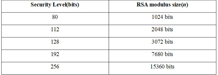
Table 2.1: Relationship of Security level and RSA modulus size
In the Tab. 2.1, the smallest security level is 80 bits, which is 1024 bits in the RSA
and unbalanced RSA algorithm. In these five security levels, the 112 bits security
algorithm is choosing 2048 bits as the n to set up the RSA or unbalanced RSA
algorithm system.
2.4.2 Lightweight and Ultra-lightweight Security
Lightweight and ultra-lightweight security is used for some special areas to provide
security services [18]. In these areas, because some special hardware reasons, the
lightweight and ultra-lightweight security is applied. In this thesis, considering the
ZigBee devices characteristics,small devices,minimal flash memory and low power
consumption, the lightweight and ultra-lightweight security is suitable for ZigBee
devices and network systems.
2.5
Comparison Between RSA and Unbalanced RSA
In current security area, the length of RSA is normally extended to 2048 bits to
make sure the cryptographic system is secure. Then, the following table shows the
difference between the RSA and unbalanced RSA.
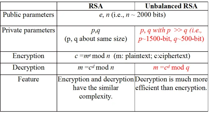
Table 2.2: Comparison between RSA and unbalanced RSA
The Tab. 2.2 has shown the differences between unbalanced RSA and RSA. It is
algorithm, the lengths of private parameters p and q are similar.Contrary to this,
the private parameter p is longer than q. Additionally, the decryption part formula
of unbalanced RSA is a special case of RSA since the RSA is modular n, but the
unbalanced RSA decryption part is only modular q, which is the shorter parameter
in the two private parameters. Because of this reason, the unbalanced RSA decryption
part is more efficient than the RSA. However, thenof RSA algorithm and unbalanced
RSA algorithm should be the same since it determines the security level of these two
algorithms; therefore, in the key generation part of unbalanced RSA, the length of p
is much larger than that of q.
2.5.1 Reasons of Choosing Unbalanced RSA
In the ZigBee system, there are FFD and RFD devices existing in the system.
Nor-mally, the end devices in the ZigBee system is only providing data transmission of
small amount; therefore, the end devices normally are the RFD devices. Because of
this reason, the calculation capacities between FFD and RFD are not the same, so
the unbalanced RSA is suitable in the ZigBee system for the communication between
FFD and RFD devices. Additionally, considering the decryption part of unbalanced
RSA is more efficient than the encryption part, unbalanced RSA algorithm is a good
choice in the ZigBee system. Furthermore, more efficient decryption part delegates
low consumption and cost in the decryption part,so unbalanced RSA is suitable for
3
AN OVERVIEW OF RELATED WORKS
3.1
Security Options for ZigBee and Bluetooth Standards
In now world wide ZigBee applications, the ZigBee security options have caused
in-creasing attractions than before. Because of the development of ZigBee technology,
three individual kinds of security options of ZigBee have been researched for many
years and achieved some results[9]. The first one is called confidentiality, which is
nor-mally using symmetrical key systems to protect the data security in the transmission
period. Specially, ZigBee technology runs the AES 128-bit algorithm in MAC layer
to ensure system confidentiality[9]. Then, the next security option is authentication,
which is used for checking the devices or messages identification to make sure there
is no modification about the devices or the messages [19]. Additionally, the last part
security question is about the key establishments, which is about these three kinds of
keys that have been mentioned before. Then, in the related work part, the two
im-portant security options, authentication and key establishment, will be introduced in
detailed and in the following parts, the basic knowledge of cryptographic technology
will be given. In the Bluetooth security options, there are also three parts used for
description of Bluetooth security, similar to the ZigBee security options. However, the
authentication part of the Bluetooth technology is not the same because it is using
the Challenge-response scheme to offer this service. The Key establishment method
has three components: XOR algorithm, using XOR to protect the key establishment;
Diffie-Hellman scheme using Diffie-Hellman scheme, a public-key crypotography
sys-tem, to protect the key delivery; unbalanced RSA algorithm is using the unbalanced
RSA algorithm, a public-key crypotography system, to protect the key transfer[9].
3.2
Key Structure in ZigBee and Bluetooth
There are three major keys existed in the ZigBee system. For understanding these
three kinds of keys in ZigBee, the keys explanations are listed as follows [20]:
• Link key: Link key is a private key used for the communication between
two devices, which is used for sending/receiving data individually. Because
of this, the link key normally is a symmetric key. Likes the AES algorithm
key, specially, the encrypt/decrypt keys are the same and the constructions are
simple,so symmetric key is popularly used for large data encryption/decryption.
However, since the encrypt and decrypt keys are the same, link key needs other
kinds of keys to make sure the link key is secure [21].
• Network key: For protecting the network integration and security, network
key is used widely in ZigBee system for authentication service for new joining
devices. The network key is a common key shared among all nodes in a ZigBee
system and is used for protecting the ZigBee network infrastructures and all
nodes should be required to possess a valid Network Key in order to utilize the
ZigBee network for transmitting and receiving data. Nodes without a valid
Net-work Key should not be allowed to join (associate) or utilize a ZigBee netNet-work
for transport. Routing nodes should validate ZigBee data packets based on the
Network Key before processing and forwarding the packet [21].
• Master key: Master key is the base of network key and link key since these
two kinds of keys are derived or generated from the master key. For the key
protection, master key is normally stored in the core devices,like the coordinator
or router. However, how to make sure the master key is secure is important
since it is the foundation of these three kinds of keys.
The Bluetooth system is not similar with the ZigBee system because there is only
technology does not use the key to authenticate devices or key architectures, the link
key is used for protecting the data transmission among devices; therefore, this key is
important in the Bluetooth technology.
3.3
On Confidentiality in ZigBee and Bluetooth
As shown the Fig. 2.2, the security is the top hot topic in the ZigBee and Bluetooth
systems. In the following subsections, the confidentiality will be explained.
Confi-dentiality means the privacy in the security area, which delegates the protection of
message security. It means although an attacker can obtain a message, he/she can not
get the message information directly if the message has the confidentiality security.
In the ZigBee system, the confidentiality is normally proposed for the data
transmis-sion between devices, from FFD to FFD or FFD to RFD [14]. The Bluetooth system
is choosing this service to protect the data transmission, too. Because of this, the
confidentiality service is using 128 bits AES to implement its security mechanisms.
The security suite is 128 bits AES algorithm model.
The AES algorithm is applied in the ZigBee device. The message is encrypted and
decrypted by the AES algorithm. Therefore, the 128 bits AES algorithm provides
the confidentiality security service in ZigBee technology.
Additionally, because the AES algorithm is used in the Bluetooth technology, it
only uses the link key to do the AES algorithm. From this section, the ZigBee and
bluetooth system security will be introduced and the security service part in ZigBee
Fig. 3.1: Security in ZigBee and Bluetooth stack[4]
3.4
On ZigBee Authentication
Authentication is an important security service in the security area, which is used for
providing the process of giving individuals access to system objects based on their
identity. In the ZigBee technology, there are normally three different components in
the authentication services: certificate authentication, message authentication code
and network key. In the following subsections, these three methods will be shown [22].
3.4.1 Certificate Authenticaion
The certificate authentication in the security service is using the certificate to
au-thenticate the device identity [22]. In the ZigBee network certificate authentication,
these are five different roles in this kind of service: Global Virtual Certificate
Author-ity(GVCA),Trust Center(TC),Manufacturer’s Certificate Authority(MCA),
This method is illustrated with two authentication parts as follows:
Fig. 3.2: Authentication protocol between TC and MCA
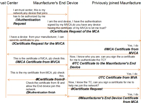
Fig. 3.3: Authentication protocol between TC and MED through MCA
In the Fig. 3.2, during the first step of certificate authentication, the MCA should
set up the connection with TC first. Before the protocol is started, all ZigBee devices
are having the certificate from the GVCA to identify their identity. In this period,
there are 11 steps. The steps are shown below:
to join this network.
2.MCA feeds back the TC asking for the certificate of TC to make sure the TC
identity.
3.The TC feeds the certificate signed by GVCA to the MCA and ask the MCA
certificate for the MCA identification.
4.After the MCA received the certificate from TC, the MCA verifies the certificate.
5.The MCA will ask the challenge response from TC to make sure the owner of
the TC is true. Additionally, the MCA will send the MCA certificate signed by the
GVCA back to the TC to help the TC to verify the MCA identification.
6.The TC will decrypt the challenge and send the response back to MCA to verity
its identity.
7.The challenge from the TC to MCA is sent to MCA to help the TC to verity
the MCA identity.
8.The MCA will verify the decryption result from TC and decrypted the challenge
from the TC.
9.The MCA will feed the response back to TC.
10.The TC needs to verify the response from the MCA: if the response is the same
with the stored one, the certificate authentication part is finished.
In the Fig. 3.3, there are eleven steps to set up the the authentication of MED:
1.The TC sends the authentication request to MED.
2.The MED sends the MCA authentication request to TC.
3.Because the TC and MCA have set up authentication before, the TC will send
the MVCA certificate request to MCA.
4.The MCA will send the MVCA to TC because the TC and MCA have the
authentication before.
5.After getting the MVCA from the MCA, the TC will send the MVCA certificate
6.After the MED authenticating the MCA, the MED will ask the certificate from
the MCA to help the MED authenticate the TC.
7.The MCA sends the TC certificate to MED to help MED to set up authentication
of TC.
8.After the MED authenticated the TC, the MED requests the MCA to help it
join the existing network.
9.The MCA feeds back the Manufacturer’s End Device Certificate to MED.
10.The MED sends the Manufacturer’s End Device Certificate to TC to
authen-ticate itself.
11.After the TC receiving the Manufacturer’s End Device Certificate from MCA,
the TC should check this certificate. If the certificate authentication complete
suc-cessfully, the MED will be allowed to join the existing network of TC.
12.The TC will tell the MCA that it is accepted to join the existing network.
After these two protocols, the MED device authentication is finished. This is
the certificate authentication in the ZigBee technology. Then, other two kinds of
authentication methods will be shown in the following sections.
3.4.2 Message Authentication Code
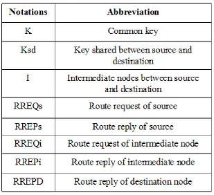
This message authentication code method is proposed by Suhas Kulkarni, Uttam
Ghosh and Haribobu Pasupuleti. First the notation and abbreviation are shown as
Table 3.1: Notation and Abbreviation in MAC
Then, the next graph shows the MAC authentication protocol in 14 steps.
Fig. 3.4: MAC Authentication Protocol
through some intermediate node in the route path. The 14 steps are shown in detail
as below:
1.The source node should generate theRREQs,MAC’sandMAC(sd). MAC’sand
MAC(sd) is generated as follows:
MAC’s=H(RREQs,K)
MAC(sd)=H(RREQs,Ksd)
(12)
The H denotes the hash function.
2.Then, after these three parameters are generated, they will be sent to the
inter-mediate node from the source node.
3.After receiving these parameters, the intermediate node should generateMACG.
If MACG == MAC’s, the intermediate node should generate the MAC’p.Until now,
the source node authentication is successful. Then, theMACiis generated as following
steps. These parameters are generated as next equations.
MACG =H(RREQs,K)
MAC’p=H(RREP,K)
MACi =H(RREQi,K)
(13)
4.Intermediate node feeds the RREP and MAC’p back to the source node.
5.Then, the source node needs to create the RRCP and judge whether MACP
equals to MAC’p. If MACP equals to MAC’p, the intermediate node authentication
is successful.
6.The source node sends RREQs,route path, data, MAC(sd) and K(sd).
7.From this step, the intermediate node will set up the authentication to
destina-tion node. The intermediate node sends RREQi,MACi and MAC(sd).
generateMACGi to do the authentication, if authentication is successful, theMAC’pi
is created. Additionally, these two parameters is set as follow equations:
MACGi=H(RREQi,K)
MAC’pi=H(RREPi,K)
(14)
9.Then, the destination will send these two parameters to intermediate node to
do the destination node authentication.
10.The intermediate node needs to generate MACPi in the equation 15 to judge
whether MACPi equals to MAC’pi to authenticate the destination node.
MACPi=H(RREPi,K) (15)
11.After the intermediate node finished the destination and intermediate nodes
authentication, the RREQs, route path, data, MAC(sd) and K(sd) are sent from
intermediate node to the destination node.
12.After the data transfer, the destination node generates the MAC(sd’) to do
the source node authentication. If this authentication is successful, the MAC’D and
MACsd are generated to feed back to the source node to authenticate the destination.
These three parameters are following the equation 17.
MAC(sd’)=H(RREQs,Ksd)
MAC’D=H(RREPD,K)
MACsd=H(RREPD,Ksd)
(16)
13. After the three parameters are generated at destination node, they are back
to the source node.
14. After receiving these parameters coming from the destination node, the source
authenti-cation is successful, the source node generates the MACsdb to finish the destination
node authentication. The generation parameters are calculated as follows [22]:
MAC’Dc=H(RREPD,K)
MACsdb=H(RREPD,Ksd)
(17)
In this MAC protocol, the device and key authentication are involved. Additionally,
this kind of MAC protocol is suitable for mesh network authentication because this
protocol involves the route path and all working device authentication.
3.4.3 Network Key Authentication
This kind of network key authentication is much simpler than the two authentication
protocols to set up the authentication between end device and trust center In the
fig. 3.5, the network key authentication is exhibited [22].
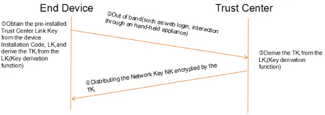
Fig. 3.5: Network key authentication
There are four steps in the fig. 3.5.
1.The end device obtains the pre-installed Trust Center Link Key from the device
Installation Code,LKi and derive the TKi from theLKi(Key derivation function).
2.The end device will send some necessary information to trust center through the
out of band method, such as web login and interaction through hand-held appliance.
will derive the TKi from the LKi(Key derivation function).
4.The trust center will Distribute the Network key NK encrypted by the TKi.
After these four steps, the end device will use the decrypted NK to join the
existing network. Additionally, these three authentication methods are discussed in
this chapter. In the next chapter, the key establishment methods will be shown.
3.5
Existing Works on ZigBee Key Management
Key establishment, also called key exchange, means the key transmission between
two devices through an insecure communication channel [23]. This security service
is allowing use of cryptographic algorithm. Because this security service is used for
the key protection, the message is only the key;therefore,the message size is small
and normally ,for protecting its security, this service in ZigBee technology chooses
the symmetric key establishment protocol for set up. In the ZigBee security, the key
establishment has two types:group key protocols and symmetric key protocols. In the
next parts, the two types are shown.
3.5.1 Group key protocols
This method is used for delivering individual keys to different devices to encrypt/decrypt
the message,which consists of the key in the message [24]. In this method, the key
establishment algorithm is using RSA algorithm in this protocol,which involves three
Fig. 3.6: Group key protocol
The special steps description are in the following:
1.The user, server and node are finishing their individual authentications and the
server should generate the algorithm parameters for node key establishment and send
the parameters to node. In this step, the node’s individual key is used for deriving
the group key in the future steps.
2.The user designates the group about the group members.
3.The server will generate the group key,which is used for protecting the
trans-mission of the delivered key.
4.After these three steps, the user needs to generate the delivered key as the
message and send it to server, which is using the plaintext form.
5.The server will help the user to encrypt the message by using the node’s key
establishment parameters.
6.After the step four, the server also needs to send the node sign to the special
node to help the node to derive the individual node key.
7.The node will derive the group key through the node’s security key and node
sign. After getting the group key, the node decrypts the message through the group
key to get the delivered key. In the next section, the Symmetric Key establishments
3.5.2 Symmetric Key Establishments
This kind of key establishment is shown in the Fig.3.7 [25], like in previous sections,
the description is shown after this graph. Additionally, the node’s symmetric key
parameters has been shared with server before this key establishment protocol [25].
Fig. 3.7: Symmetric key protocol
1. Node should send the key establishment request to server for asking the key.
2. After receiving the request, the server generates the key as the data and uses
the shared key known by node to encrypt the key.
3. The delivered key, message, is sent from the server to the node.
4. After receiving the message including the delivered key, the node will use the
shared key with server to decrypt the message to obtain the key.
5. After getting the delivered key, the node needs to acknowledge the server that
it has received the delivered key.
There are two methods on key establishments discussed in this chapter. Then,
the next subchapters will show the master key establishments methods. The master
key is the basic key of the ZigBee system key establishment. As explained before,
there are two kinds of key establishments of the ZigBee system which is using the
previously shared key. Therefore, the master key transmission is very important in the
in the ZigBee technology are realized in three methods. In the section before, the
two kinds of key establishments in ZigBee system are shown. However, these two
protocols are based on the shared keys acquired before the key establishments,so
these two protocols need shared keys to support these protocols working. Then, the
next chapter will talk about the three kinds of key transmissions of master key, which
are not introduced in this chapter because the master key is the basic key of ZigBee
system which does not have any pre-shared key before. Therefore, the three methods
of master key transports are introduced below: pre-installed, user-entered and key
transport.
3.5.3 Pre-installed Master Key
This method involves the manufacturer because the master key is installed by the
manufacturer in the manufacture period. The benefit is low cost for the ZigBee
de-vices [27]; therefore this method is popular in the master key transports. However,
because the master key is pre-installed, it is known by the manufacturer and stored
in the database of the manufacturer. Because of this, if the database of the
manu-facturer is cracked or broken by the attackers, all device master key will be known
by the attackers. Therefore, this mathod’s security has the high connection with
the manufacturer’s database security. Another disadvantage is the device delivery
period. Because the master key is installed into the device before the delivery period,
in the delivery period, it is the hands change during the delivery period. Because
of this, the master key can be modified or known in the delivery period [26]. After
considering these two disadvantages, the security level of this method, pre-installed,
3.5.4 User-entered Master Key
The next method is user-entered. This method means the master key generation has
a deep relationship with what the user entered into the system through the input
devices. If only comparing with this method with pre-installed method, the security
level of this one is much higher because this kind of master key is only known by
the user of the ZigBee device and it is not eternal master key. In addition, this
master key is initialized after the delivery period and is only known by the user [27].
However, this method is normally used for the FFD devices, like the coordinater or
router because it needs the input device. Considering this reason, the end device is
not suitable for using this method because the ZigBee devices typically need to be of
small size and low cost [13]. The input devices restrict the size and cost of ZigBee
devices; moreover, if the input devices are choosing the interfaces to reduce the size,
the interfaces delegate the higher cost in the ZigBee devices. Therefore, this method
is a great way to set up the master key but not the best choice.
3.5.5 Key-transport Master Key
After considering these two methods shown before, another suitable key establishment
used in the ZigBee device is the key-transport. This method is based on the trust
center, which is designed for the authentication or security service device. The benefit
of this method is that transmitted master key is only known by the user or the owner;
the disadvantage is this method involved the trust center, which is more complicated
than the user-enter and the pre-installed methods [13]. This method is a great way
to set up the master key; however, this approach has some disadvantages in the
application period because the question is appearing in the transport period, on using
the plaintext to transmit it or using the out-channel method to set up the master key.
For the focuser, because the ZigBee technology appeared in a short time, for reducing
the out-channel method means this channel is unprotected and open [26]. Because of
these existing master key transport methods having their own special disadvantages,
the security level of master key establishment should be improved.
3.6
Recent Works on Bluetooth Security
For the bluetooth link key key establishments, there are six existing methods and will
be introduced in the following pages. XOR gate in Bluetooth technology is a popular
method to protect the key establishment, but it is an easy way to protect the link
key. This algorithm is used widely in Bluetooth technology and the functions will be
shown [28].
3.6.1 Initialization Key Transmission
This transmission method is shown in the Fig.3.8 first and the details will be shown
below [11]:
Fig. 3.8: Initialization key transmission protocol
1. The Bluetooth Device 1 and Bluetooth Device 2 need to enter PIN to set up
the connection.
2. The Bluetooth Device 1 generates the Rinit randomly, then creates the Kinit =
E22(Rinit, P IN, L). In this formula, the L delegates the length of PIN. In addition,
Kinit. Additionally, the IDBD1- Identification of Bluetooth Device 1 is stored in the
Bluetooth Device 1.
3. After these parameters generation, the Rinit is sent from the Bluetooth Device
1 to Bluetooth Device 2.
4. While the Bluetooth Device 2 receiving the Rinit from the step three, the
Bluetooth Device 2 should create the Kinit = E22(Rinit, P IN, L) and C2=R2 XOR
Kinit, where R2 is the random generation. Furthermore, the IDBD2- Identification of
Bluetooth Device 2 is stored in the Bluetooth Device 2.
5. Additionally, the C1,C2, IDBD1 and IDBD2 will be exchanged between the
Bluetooth Device 1 and Bluetooth Device 2.
6. Then, after these information exchanges, the Bluetooth Device 1 and Bluetooth
Device 2 will figure out the following steps individually: for the Bluetooth Device
1,there are four steps existing in this step, R2=C2 XOR Kinit,K1 =E21(R1,IDBD1),
K2 =E21(R2,IDBD2) and K1-2 =K1 XOR K2. The next part in this step is for the
Bluetooth Device 2. The steps are similar with Bluetooth Device 1, R2=C2 XOR
Kinit, K2 =E21(R2,IDBD2),K1 =E21(R1,IDBD1) and K1-2 =K1 XOR K2.
After these six steps, the shared keys are known by each other in the initialization
key transmission and the E21 and E22 are custom key generator in the Bluetooth
standard. The next key transmission protocol is the Unit key transmission protocol.
3.6.2 Unit Key Transmission
This key transmission protocol is using XOR algorithm to protect the key delivery
by using theKinit and this method is illustrated in the following graph. Additionally,
the Kinit is shared before this transmission start with plaintext communication after
Fig. 3.9: Unit key transmission protocol
This is a simple key transmission. The security level is very low. Then, the next
subsection is for the combination key transmission.
3.6.3 Combination Key Transmission
In this subsection, a new key transmission protocol is introduced, combination key
transmission. As other key transmission protocols shown before, the Fig.3.10
de-scribes this protocol first.
Fig. 3.10: Combination key transmission protocol
For a details description, there are seven labels in used the Fig.3.10 and they will
be shown first. E21: Custom key generation algorithm in Bluetooth standard; Kinit:
Initialization key; K1-2:Combination key;AK RAND1: Random number generated by
Bluetooth Device 1; AK RAND2: Random number generated by Bluetooth Device
Device 2. Then, there are five steps in this protocol:
1. The Bluetooth Device 1 needs to generate the AK K1 =E21(AK RAND1,BD
ADDR1) and C1=AK RAND1 XOR KINIT.
2.The Bluetooth Device 1 needs to send C1 from step 1 to the Bluetooth Device
2.
3 After the Bluetooth Device 2 receiving the message from step 2, it will generate
two parameters, AK K2 =E21(AK RAND2,BD ADDR2) and C2=AK RAND2 XOR
KINIT.
4. The Bluetooth Device 2 will feed back the C2 to Bluetooth Device 2.
5. This process has two parts, for the Bluetooth Device 1 and 2. These steps are
processed at the same time. For the Bluetooth Device 1, the AK RAND2=C2 XOR
KINIT; AK K2=E21(AK RAND2,BD ADDR2) and K1-2 =AK K1 XOR AK K2.
Ad-ditionally, for the Bluetooth Device 2,AK RAND1=C1 XORKINIT;AK K1=E21(AK
RAND1,BD ADDR1) and K1-2 =AK K1 XOR AK K2.
After these five steps, the key has been known by each other, so the key delivery
is finished.
3.6.4 Master Key Transmission
The simple key delivery protocol has three steps and this protocol is shown in the
Fig.3.11.
There are three steps to help the Bluetooth Device 1 to Bluetooth Device 2[11]:
1. The Bluetooth Device 1 should generate three parameters: Kmaster=E22(RAND1,
RAND2,L); OVL=E22(Klink,RAND,L) and C=OVL XOR Kmaster. In this step, the
L delegates the length of PIN.
2. The Bluetooth Device 1 should send theRANDandCto the Bluetooth Device
2.
3. After these two steps, the Bluetooth Device 2 needs to generateOVL=E22(Klink,
RAND,L) to obtain the Kmaster through Kmaster=OVL XOR C.
Through the step 1 to 3, the Bluetooth Device 2 can obtain the master keyKmaster.
In the following subsection, the Diffie-Hellman scheme will be shown.
3.6.5 Diffie-Hellman Scheme
As the description before, the Diffie-Hellman scheme is shown in the Fig.3.12 with
six processes.
Fig. 3.12: Diffie-Hellman scheme
The detailed steps in the Fig.3.12 will be shown below[11]:
1. Bluetooth Device 1 generates x= DH Key and IDBD1. The IDBD1 is the
Identification of Bluetooth device 1. Then, the Bluetooth Device 1 should computes
thegxas the public key. After these, the Bluetooth Device 1 also needs to generate the
in this step. After generating these parameters, the x,gx,Cand IDBD1 are stored in
this device for the following steps.
2. The Bluetooth Device 1 should send these parameters in the step 1 to the
Bluetooth Device 2.
3. The Bluetooth Device 2 needs to store the IDBD2, Identification of Bluetooth
Device 2, computes C’=M AC(K, gx). After these, if C’==C, the authentication of
Bluetooth Device 1 is successful.
4. After the authentication of Bluetooth Device 1 is successful, the Bluetooth
De-vice 2 should generatey randomly as the DH key. Then, this device should computes
theSfollowing the functionS=gxy= DH shared. After these, theK
link=KDF(P IN,S,
C,K, IDBD1, IDBD2) andEk=KDF(K, IDBD2) should be obtained in the
Blue-tooth Device 2.
5. In this step, thegy, IDBD2 andEk’ need to be sent to Bluetooth Device 1 from
the Bluetooth Device 2.
6. After receiving these information from step 5, the Bluetooth Device 1 will
compute S=gxy =DH shared, K
link=KDF(P IN,S,C,K, IDBD1, IDBD2). Then,
this device will decrypt theEk’=KDF(S, IDBD2). If the decryptedK== storesK,
the Klink will be accepted.
In this key establishment method, the KDF delegates a custom function of K in
the Bluetooth standard. Then, the last method, unbalanced RSA algorithm protocol
is shown.
3.6.6 Unbalanced RSA Protocol
Fig. 3.13: Key establishment protocol in Bluetooth using unbalanced RSA
In the Fig.3.13, there are seven steps displayed in the following descriptions
be-tween two Bluetooth devices.
1. The Bluetooth Device 1 should generate theKrandomly, then compute theC=
Ke mod n and H=MAC(K,C). After these computations, the H,K,C,e and IDBD1
will be stored in the Bluetooth Device 1. At the same time, the Bluetooth Device 2
should store the IDBD2 itself for the next steps. Additionally, the Bluetooth Device
1 should broadcast public parameters of unbalanced RSA to the Bluetooth Device 2.
2. The Bluetooth Device 1 and 2 need to establish connection through the PIN
entry: if the PIN authentication is successful, the connection is set up.
3. The Bluetooth Device 2 has to feed the IDBD2 back to Bluetooth Device 1.
4. After these three steps, the Bluetooth Device 1 will send K,C, IDBD1 and H
to Bluetooth Device 2.
5. After receiving these parameters from step 4, the Bluetooth Device 2 needs to
decrypt theCthrough K= (Cd)modp. Then, it needs to computeH’=M AC(K,C).
If H’==H, Bluetooth Device 1 authentication is successful. After these, the
Blue-tooth Device 2 will computes K’ = Hash(K), HR=(K’ XOR H’ XOR IDBD2),
Klink=HASH(PIN,K,H,IDBD1,IDBD2).
7. As the last step, the Bluetooth Device 1 will computeK’=HASH(K),Klink=HAS
H(PIN,K,H,IDBD1,IDBD2) and recoverK’fromHR. If theK’==K’, theKlink
trans-mission is successful.
After these six methods key establishments in the Bluetooth technology displayed,
the more authentication and challenge-response scheme works will be shown in the
following pages.
3.6.7 Authentication in Bluetooth
The authentication part in the Bluetooth technology has one method,
Challenge-response scheme, which is described as following subsection [10].
3.6.8 Challenge-response Scheme
For the details of this scheme, the next figure, Fig.3.14 shows the protocol’s details.
Fig. 3.14: Challenge-response scheme protocol
In the Fig.3.14 [10], the link key is shared by Unit A and Unit B before the
protocol is started. The Unit A is also defined Challenger and the Unit B is defined
Clainmant. Specially, there are six processes in the next part.
1. The Challenger, Unit A, needs to generate a random input,donated by the
AU RANDA.
3. After receiving theAU RANDAfrom Challenger, Unit A, the Claimant, Unit B,
should generate a random input, AU RANDB.
4. The Claimant, Unit B, needs to create the SRESB, by usingE1(AU RANDA,
AU RANDB,LinkKey) to obtain the SRESB.
5. The Claimant, Unit B, needs to feed back the AU RANDB and SRESB to the
Challenger, Unit A.
6. The Challenger, Unit A, will generate the SRESA from E1(AU RANDA,
AU RANDB,LinkKey) and then the Challenger, Unit A, will compare with SRESB.
If the SRESA ==SRESB, the authentication is successful.
Additionally, the E1 in the steps is a custom algorithm in the Bluetooth standard,
4
PROPOSED WORKS
Because the ZigBee device needs the small size and low cost, the security requirements
are not the same. Additionally, for making sure the master key establishment is
secure, there are two individual methods of master key establishments explained in
the following subsections [29].
4.1
New Master Key Establishment Protocol in ZigBee
In this part, one new method for master key establishment is proposed. For getting
the details of this method, the Fig.4.1 indicates the special steps.
Fig. 4.1: Master key establishment protocol by unbalanced RSA algorithm
This protocol is named the full version because it uses the unbalanced RSA
algo-rithm to support the confidentiality service and the authentication service. there are
nine steps existing in it.
1.End device provides its certificate or ID coming from the manufacturer and
timestamps to help the coordinator/router to check its identity.
2.After receiving these messages coming from the end device,the coordinator/router
check the certificate or ID and timestamps from the step one to authenticate the end
![Fig. 2.1: Star Topology in ZigBee system[1]](https://thumb-us.123doks.com/thumbv2/123dok_us/1368268.1169577/21.612.218.423.327.423/fig-star-topology-in-zigbee-system.webp)
![Fig. 2.2: Cluster tree Topology in ZigBee system[2]](https://thumb-us.123doks.com/thumbv2/123dok_us/1368268.1169577/22.612.146.507.70.332/fig-cluster-tree-topology-in-zigbee-system.webp)
![Fig. 2.3: Mesh Topology in ZigBee system[1]](https://thumb-us.123doks.com/thumbv2/123dok_us/1368268.1169577/23.612.239.413.73.206/fig-mesh-topology-in-zigbee-system.webp)
![Fig. 2.4: Topology in Bluetooth system[3]](https://thumb-us.123doks.com/thumbv2/123dok_us/1368268.1169577/24.612.206.446.74.180/fig-topology-in-bluetooth-system.webp)
![Fig. 3.1: Security in ZigBee and Bluetooth stack[4]](https://thumb-us.123doks.com/thumbv2/123dok_us/1368268.1169577/35.612.163.481.71.320/fig-security-in-zigbee-and-bluetooth-stack.webp)