Development of the Technical Basis for a New Regulatory Guide
for Leak-Before-Break (LBB) Applications
Paul Scott1, Rick Olson1, Frederick W. Brust1, Gery Wilkowski2, Cayetano Santos3, Matthew Mitchell3, and Keith Wickman3
1 Battelle-Columbus, 505 King Avenue, Columbus, Ohio 43201
2 Engineering Mechanics Corporation of Columbus, 3518 Riverside Drive, Suite 202, Columbus, Ohio 43221-1735
3 US Nuclear Regulatory Commission, Mail Stop T10-E10, 11545 Rockville Pike, Rockville, Maryland 20852
ABSTRACT
In the mid 1980’s the US Nuclear Regulatory Commission (USNRC) began to accept Leak-Before-Break (LBB) for large-diameter, high quality piping systems as a means of enhancing safety. To aide NRC staff evaluating LBB submittals, a draft Standard Review Plant (SRP) entitled “Leak-Before-Break Evaluation Procedures” was published in 1987. Because of ongoing research, this draft SRP was never published in final form. Now that the research is nearly complete, the NRC has decided to update their LBB procedures through the publication of a new Regulatory Guide for LBB. Consequently, in 1997 the NRC contracted with Battelle to conduct a study entitled “Technical Support for a Regulatory Guide on LBB Evaluation Procedures”.
During this study, a three-tiered approach to LBB was developed. Level 1 is the simplest level of assessment, designed to provide a conservative LBB assessment. Level 1 was designed such that piping systems that readily passed an LBB evaluation in the past would pass Level 1 as well. Level 2 is similar to the draft SRP procedures, except it incorporates enhancements in technology that have resulted from recent research. Two of these enhancements that will be discussed in detail in this paper are the effect of restraint of pressure induced bending and the effect of weld residual stresses on the crack-opening displacement analyses traditionally used in LBB assessments. Level 3 is the most complex level of assessment, where nonlinear stress analyses are used to take advantage of margins that exist when one invokes elastic analysis in a nonlinear problem. Level 3 would only be applied in those cases where one could not demonstrate LBB using either a Level 1 or 2 approach. Each of these levels of assessment will be discussed individually as part of this paper. In addition, case studies of actual piping systems were conducted and will be presented to demonstrate the relative conservatism of the three levels of assessment.
KEY WORDS: leak-before-break, LBB, crack-opening displacement, tiered approach, weld residual stresses, margin, pressure, bending
EXISTING CRITERIA APPLICABLE TO LBB
Currently, the key regulation in the United States related to LBB is General Design Criterion-4 (GDC-4), “Environmental and Dynamic Effects Design Bases” in Appendix A of Part 50 of Title 10 of the Code of Federal Regulations (i.e., 10 CFR 50). Of particular interest to the subject of LBB is the stipulation in GDC-4 that allows the use of “analyses reviewed and approved by the Commission” to eliminate from the design basis the dynamic effects of pipe ruptures. The means of implementing this stipulation are applicable Regulatory Guides and Standard Review Plans.
Regulatory Guides provide guidance to licensees and applicants on implementing specific parts of the NRC’s regulations, techniques used by the staff in evaluating specific problems or postulated accidents, and data needed by the staff in its review of applications for permits or licenses.
Standard Review Plans, on the other hand, are prepared for the guidance of the Office of Nuclear Reactor Regulation (NRR) staff responsible for the review of applications to construct and operate nuclear power plants. SRPs are not substitutes for Regulatory Guides or the Commission’s regulations, and compliance with them is not mandatory.
Transactions of the 17th International Conference on
Structural Mechanics in Reactor Technology (SMiRT 17)
Prague, Czech Republic, August 17 –22, 2003
• Draft SRP 3.6.3 (Leak-Before-Break Evaluation Procedures) is generally applicable to Class 1 and 2 piping systems with a few notable exceptions, e.g., it cannot be applied to discrete locations or individual welded joints, it cannot be applied to piping systems susceptible to stress corrosion cracking, fatigue, creep damage, water hammer, or piping systems for which brittle fracture is a possibility.
RECENT RESEARCH RESULTS - ENHANCEMENTS IN THE TECHNOLOGY APPLICABLE TO LBB
The main reason draft SRP 3.6.3 was never published in final form is that there were a number of outstanding technical issues to be resolved through further research when it was first published. Some of the pertinent research that has been conducted since the initial publication of the draft SRP 3.6.3 include:
Leak-rate analyses – A number of factors that may influence the postulated leakage crack size analysis for an LBB assessment have been studied over the past few years. These factors include:
• the selection of the proper crack morphology parameters [1],
• the effect of the restraint of pressure induced bending on the predicted crack-opening-displacements (COD) [2],
• the effect of weld residual stresses on the predicted COD [3],
• the impact of the postulated leaking crack being oriented such that it is not coincident with the maximum bending plane for the transient load condition [4], and
• the effect of other uncertainty issues on LBB, such as particulate plugging in leaking cracks [5]. Note, the effects of restraint of pressure induced bending and weld residual stresses on COD analyses for LBB assessments will be considered in detail in the Case Studies presented near the end of this paper.
Material issues – Some of the key materials related research topics recently addressed include:
• cyclic load effects on material toughness [6],
• dynamic strain aging effects on the strength and toughness of ferritic steels at light water reactor (LWR) temperatures [7],
• cracks in welds, including bimetallic welds and weld fusion line toughness concerns [8 and 9],
• thermal aging of cast stainless steels and stainless steel welds [10],
• toughness degradation of wrought stainless steels with high sulfur contents [11],
• anisotropy effects on the fracture toughness of ferritic piping and the impact such effects may have on piping systems subjected to high torsional stresses [12], and
• J-R curve extrapolation techniques necessary for predicting large amounts of crack growth from small-scale specimens [13].
Stress analysis issues – One of the key issues in this regard is the effect that nonlinearities have on LBB assessments. The nonlinearities can have a significant impact on LBB and are the prime motivator behind the use of a Level 3 LBB assessment in those cases where LBB cannot be demonstrated using the more traditional Level 2 assessment. A series of case studies looking at this effect are included in the Case Studies section of this paper.
Fracture/stability analyses – When the draft SRP 3.6.3 on LBB was first published, the state-of-the-art in pipe fracture analyses was limit-load analyses for high toughness and/or small diameter pipe and either a modified limit-load analysis, using something like a Z-factor approach, or a very limited number of elastic-plastic fracture mechanics (EPFM) J-estimation schemes (e.g., Paris/Tada [14] and GE/EPRI [15]) for those piping systems for which limit-load conditions did not exist. For crack stability analyses, the tearing instability J/T approach was most often used. Since that time, considerable resources have been expended in developing new EPFM analysis methods, improving and expanding the realm of application of these methods, and validating these methods.
crack sizes. As part of Reference 16, another sensitivity study was undertaken to examine the validity and conservatism of some of these J-estimation scheme based COD predictions by comparing their results with finite element analyses. From this assessment it was found that the Paris/Tada COD predictions were conservative, and in some situations excessively conservative, from an LBB perspective with respect finite element analyses, while the original GE/EPRI COD predictions were more in agreement with the finite element results at the load levels more representative of normal operating conditions. Thus, it was concluded that one should use the original GE/EPRI COD methodology with the statistically determined crack morphology parameters recommended in NUREG/CR-6004 [17] for determining the COD.
PROPOSED TIER APPROACH TO LBB
One of the prime objectives behind the program discussed in this paper was the development of a tiered approach to LBB. Further details of this tiered approach can be found in Reference 16. The simplest level of assessment is Level 1. The Level 1 approach was developed to offer the applicant a simple, yet conservative, methodology by which they could apply for LBB without having to utilize some of the advanced leak-rate or fracture mechanics codes. In lieu of the use of leak-rate codes for predicting the postulated leakage flaw size, a series of simple, empirically-derived influence functions were developed for predicting the crack-opening displacements (COD), and in turn the postulated leakage size flaw at the normal operating conditions. (Alternatively, a series of simple, closed-form shell-theory based solutions are available for predicting the postulated leakage flaw size.) Conservatism has been built into these influence functions through their empirical development and their use of the Paris/Tada COD expressions as their technical basis. In lieu of the use of some of the advanced fracture mechanics codes (J-estimation schemes, J/T analyses, or finite element analyses) for predicting the critical crack sizes or the crack stability, a simple modified limit-load analysis was used to make the fracture predictions for Level 1.
The Level 1 criteria incorporate a Level 1 specific screening criteria to preclude its use outside its realm of applicability. For instance, the screening criteria excludes the use of Level 1 to small diameter piping for which restraint of pressure induced bending effects may restrict the amount of crack-opening, thus adversely affecting the postulated leakage crack size analysis from an LBB perspective.
Furthermore, the Level 1 criteria was designed such that piping systems that had readily passed LBB using the existing draft SRP 3.6.3 methodology (e.g., main coolant loop piping in PWRs), would pass the Level 1 criteria as well.
If the piping system fails to satisfy either the Level 1 acceptance criteria or all of the elements of the Level 1 specific screening criteria, the applicant’s next logical step would be to try to demonstrate LBB using the Level 2 approach. As an illustrative example, when a Level 1 analysis was applied to an actual surge line (using data gleaned from an actual LBB submittal), it was found that the Level 1 margin on crack size was less than 2.0, i.e., the critical crack size was less than twice the postulated leakage crack sizes, [16]. As such, this piping system failed to meet one of the acceptance criteria for a Level 1 application1. However, when this same piping system was analyzed using the Level 2 criteria, it was found that the resultant margin on crack size was approximately 3, which easily satisfies this element of the acceptance criteria.
It is envisioned that the vast majority of future LBB applications will be based on the Level 2 approach to LBB. The Level 2 approach is structured in the motif of the existing draft SRP 3.6.3 procedures, except it will incorporate a number of the recent enhancements in the technology that have arisen from the recent NRC-initiated research. These enhancements include:
• the use of the best leak rate codes, with the most appropriate crack morphology parameters. As part of this study it was shown that the original GE/EPRI COD analysis resulted in a reasonably accurate, yet conservative prediction of the COD from an LBB perspective when compared with finite element analyses [16].
• the use of most accurate fracture mechanics analyses for predicting the critical crack size at the transient load conditions. For most applications, this implies the use of J-estimation schemes, such as those incorporated in the fracture analysis code, NRCPIPE. It has been shown in past studies [18] that of these J-estimation schemes, the LBB.ENG2 method tended to be the most accurate when compared with full-scale experimental data, while the GE/EPRI method was
1
slightly more conservative. Either method would be acceptable for use in a Level 2 critical crack size assessment.
• accounting for the increased understanding of the material behavior of nuclear grade pipe steels. Some of the material behavior effects, that have been identified and studied since the initial publication of the draft SRP 3.6.3 on LBB, that need to be considered in a Level 2 assessment include:
o load history effects, whether it be dynamic strain aging effects on ferritic steels at LWR temperatures or cyclic effects on the material’s fracture toughness [6 and 7],
o aging mechanisms for both cast stainless steels and stainless steel welds [10],
o fusion line toughness concerns [9],
o bimetallic welds, including the impact of primary water stress corrosion cracking on the LBB behavior for such welds [8 and 19],
o toughness anisotropy of nuclear grade ferritic pipe steels [12], and
o methods for extrapolating J-R curve fracture toughness data from small-scale laboratory specimens [13].
• accounting for a better understanding of the effects of restraint of pressure induced bending, weld residual stresses, and crack face pressure on the crack opening displacement (COD) predictions used in the postulated leaking crack size analysis.
• accounting for a better understanding of the role of secondary and torsional stresses on the fracture behavior of cracked piping systems.
If after accounting for all of these enhancements (some of which promote LBB and some of which are detrimental to LBB) one cannot demonstrate LBB behavior using a Level 2 type analysis, then one has the option of applying a Level 3 analysis.
Level 3 is the most complex of three levels of assessment. It is reserved for only those cases where one cannot demonstrate LBB using a Level 2 approach. For a Level 3 analysis, the same procedures will be followed as for Level 2 in defining the postulated leakage crack size. The difference between the two levels of assessment rests in the critical crack size analysis for the transient load conditions. Whereas Level 2 analyses use linear stresses, possibly extracted from a stress report, Level 3 analyses attempt to take benefit of the inherent margins one might realize by using a nonlinear analysis. The inherent margin is realized by accounting for the increased energy absorption necessary for plastically deforming the pipe and the crack. The more energy absorbed by this plastic deformation, the less energy available for driving the crack.
CASE STUDIES – EVALUATION OF THE TIERED APPROACH TO LBB
Three sets of test cases are presented. In the first two, the impact of two recently investigated effects on LBB, as they would apply to a Level 2 assessment, are discussed. These are the effect of restraint of pressure induced bending and the effect of weld residual stresses on crack-opening
displacement analyses used in a Level 2 LBB assessment. In the third set of test cases, the effect of using nonlinear stress analyses on a Level 3 LBB assessment is discussed. The results from these case studies are summarized in Table 1. Detailed discussion is provided next.
Effect of Restraint of Pressure Induced Bending on LBB – In Test Case 1 (Table 1), the role of the restraint of pressure induced bending on the crack-opening displacements and associated leakage through-wall crack size for an LBB analysis was assessed. For this assessment, actual data from an LBB submittal for a surge line in a PWR was used. The exact location under consideration was the weld joint where the surge line joined to the pressurizer. For this comparative analysis, a baseline analysis was first conducted where the effect of restraint of pressure induced bending was not considered. Using the SQUIRT4 (Seepage Quantification of Upsets In Reactor Tubes) module in the Windows® version of SQUIRT (Windows Version 1.1), the leakage crack length and associated crack opening displacement were calculated. For the unrestrained condition, the leakage crack length was 204 mm (8.03 inches) and the associated COD was 0.549 mm (0.02163 inches). Next, the equations in Reference 2 were used to calculate the rcod values2 for both the symmetric and asymmetric restraint cases. For both cases, the
2
normalized restraint lengths (L/D) were first calculated from the rotational stiffness at the surge
line/pressurizer weld joint using a finite element analysis of this surge line. Note, neither the symmetric nor the asymmetric analysis is totally valid for this case. This restraint of the piping system at this weld joint is highly asymmetric with the L1/D value being 0.14 and the L2/D value being 29, but the asymmetric analysis was developed for a specific R/t ratio, R/t = 10, and the R/t ratio of this piping system is 5. Thus, since neither analysis method was truly valid, both were considered for illustrative purposes.
Table 1. Results from test case analyses
Test Case
Purpose of Test Case Leakage
Crack Size, mm
Critical Crack Size, mm
Margin Additional Margin
1a Baseline case – ignoring restraint of pressure induced bending
204 293 1.44
1b Accounting for restraint of pressure induced bending
216 293 1.36 0.94
2a Baseline case – ignoring weld residual stresses
244 394 1.62
2b Accounting for weld residual stresses 266 394 1.48 0.91
3a1 Baseline case – elastic uncracked pipe analysis
230 119 0.52
3a2 Accounting for nonlinearities due to uncracked pipe
230 230 1.00 1.93
3b1 Baseline case – elastic uncracked pipe analysis
230 200 0.87
3b2 Accounting for nonlinearities due to presence of the crack
230 230 1.00 1.15
3c1 Baseline case – elastic uncracked pipe analysis
230 4 0.017
3c2 Accounting for nonlinearities due to crack and the pipe
230 230 1.00 57
It was found that the effect of restraint of pressure induced bending was minimal for both analysis methods. For the asymmetric analysis, the rcod value was 1.000 which meant that the restrained COD value was the same as the unrestrained value. For the symmetric analysis, the rcod value was 0.969 which means that the restrained COD value is 0.969 times the unrestrained value. As a result, the leakage crack length is proportionately longer. Using a trial and error approach for a SQUIRT2 analysis, it was found that the resultant 1.9 lpm (5 gpm) leakage crack length for this restrained COD value was 216 mm (8.5 inches), compared with 204 mm (8.03 inches) for the unrestrained case.
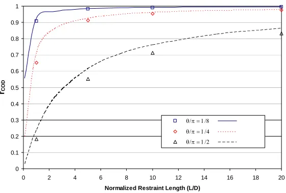
Thus, even for this highly restrained case (i.e., where the piping system joins to a large pressure vessel), the effect of this restraint on pressure induced bending is relatively minor. The only time when this effect could have a major impact is for very small diameter pipes where the LBB postulated leakage crack size (2/Β) is large, see Figure 1.
0 0.1 0.2 0.3 0.4 0.5 0.6 0.7 0.8 0.9 1
0 2 4 6 8 10 12 14 16 18 20
Normalized Restraint Length (L/D)
rCO
D
θ/π = 1/8 θ/π = 1/4 θ/π = 1/2
Figure 1. Comparison of normalizing factor between the analytical expression and the finite element calculations. Symmetric restraint, R/t = 5.
Effect of Actual Margins on LBB using a Level 3 Analysis – As part of this assessment three sets of comparative analyses were conducted. In each case the piping system under consideration was the IPIRG (International Piping Integrity Research Group) pipe loop facility. This was a 16-inch nominal diameter Schedule 100 piping system fabricated as an expansion loop. The load history used in these test cases was an increasing amplitude, single-frequency, sinusoidal forcing function superimposed on an increasing ramp. The cyclic frequency was set at about 90 percent of the first natural frequency of the pipe loop. This was the same forcing function used in a number of the IPIRG-1 pipe-system experiments [20]. The internal pipe pressure and temperature were representative of pressurized water reactor (PWR) conditions, i.e.,15.5 MPa (2,250 psi) and 288 C (550 F).
The postulated leakage crack size used in the analysis was based on TP304 stainless steel material data. The applied moment value at the assumed normal operating conditions for the postulated leakage crack size analysis was established by assuming that the primary membrane (Pm) plus primary bending (Pb) stresses at normal operating conditions was equal to 0.73 Sm. For a 1.9 lpm (0.5 gpm) leakage detection system, the calculated leakage crack size (using a SQUIRT4 analysis) was 230 mm (9.06 inches), which is approximately 18 percent of the outside pipe circumference.
In the first set of comparative analyses (Case 3a), the additional margin on crack size due to using elastic analyses to analyze a nonlinear problem was estimated. This test case involved two sets of uncracked piping system analyses. In one case, elastic analysis was used. In the other case, plasticity due to pipe yielding was introduced into the piping system analysis. The nonlinear plasticity analysis was conducted first. This time-history analysis was run until the moment at the postulated crack section
reached a value equal to the maximum moment capacity of the postulated leakage crack (i.e., 230 mm [9.06 inch] long crack). The maximum moment for this crack size was calculated using the GE/EPRI analysis to be 452 kN-m (4,000 in-kips). For these analyses it was assumed that the entire piping system was
fabricated from TP304 stainless steel pipe. The uncracked elastic analysis was run next. The same displacement time history as used in the nonlinear analysis was used in the elastic analysis as well. This elastic analysis was run for the same amount of time as it took to reach the maximum moment value in the uncracked nonlinear plasticity analysis, i.e., telastic = tnonlinear at max moment. Due to nonlinearities in the
mm (4.69 inches) versus 230 mm (9.06 inches). The bottom line is that the additional margin on crack size due to using an elastic analysis to analyze a piping system which is locally yielding is equal to the ratio of the critical crack sizes, i.e.,
Additional Margin = 2ccrit nonlinear/2ccrit elastic (1)
For this particular test case, the additional margin on crack size due to the nonlinear behavior is 1.93.
For the second set of comparative analyses (Case 3b), the additional margin due to the nonlinear behavior of a wall crack is assessed. The same piping system, same postulated leakage through-wall crack, same forcing function, same material, and same operating conditions as assumed for Case 3a, were assumed here. The first analysis conducted as part of this test case was a linear piping analysis, but with a nonlinear spring representation of the postulated leakage crack introduced at the postulated crack location. This analysis was run until the maximum moment value at the crack location reached the maximum moment capacity of the postulated leakage crack size (i.e., 230 mm [9.06 inches]), i.e., 452 kN-m (4,000 in-kips). Next an elastic, uncracked pipe analysis was run, using the sakN-me forcing function, out to a time equal to the time necessary to achieve the maximum moment value in the previous elastic, TWC analysis, i.e., 2.41 seconds. The maximum moment values and corresponding critical crack sizes for these two analyses were compared to assess the additional margin due to the presence of the crack, and its associated nonlinear behavior, i.e.,
Additional Margin = 2ccrit elastic crack analysis/2ccrit elastic uncrack analysis (2)
In this case 2ccrit elastic crack analysis equals the postulated leakage crack size (i.e., 230 mm [9.06 inches]) by definition. The value 2ccrit elastic uncrack analysis is the critical crack size for the maximum moment value (500 kN-m [4,430 inch-kips]) determined during the elastic uncracked analysis when the displacement-time history is run out to the time necessary to achieve the maximum moment value in the elastic cracked analysis, i.e., 2.41 seconds. As can be seen in Table 1, the additional margin due to the presence of the crack is 1.15. Thus, it appears that the additional margin due to the nonlinear behavior of the crack is not as great as the additional margin due to the nonlinear behavior that occurs due to the pipe yielding, at least for this set of test cases analyzed.
For the final set of comparative analyses (Case 3c), the additional margin due to the combination of the nonlinear behavior of the pipe and the presence of the crack is assessed. For this assessment, the critical crack size for a nonlinear pipe (with a crack) analysis is compared with the critical crack size for an elastic uncracked pipe analysis. These analyses were conducted in a similar fashion as for the other two test cases (3a and 3b). For this assessment, the additional margin is the ratio of the critical crack size from the nonlinear cracked analysis to the critical crack size from the elastic uncracked analysis, i.e.,
Additional Margin = 2ccrit nonlinear crack analysis/2ccrit elastic uncrack analysis (3)
As can be seen in Table 1, the additional margin on crack size due to the combined effect of using an elastic analysis to analyze a nonlinear problem and the presence of the crack is over 50 to 1. This very large margin is the result of the fact that the critical crack size for the moment value for the elastic uncracked analysis (1,330 kN-m [11,800 in-kips]) is only 4 mm (0.16 inches). Maybe a more realistic assessment of margin would be that which would result from a comparison of moments, and not crack size. The additional margins based on moments would be:
• 1.44 due to the nonlinearities associated with yielding in the pipe, i.e., 652 kN-m divided by 452 kN-m,
• 1.11 due to the nonlinearities associated with the crack, i.e., 500 kN-m divided by 452 kN-m, and
• 2.95 due to the combined effect of pipe yielding and the presence of the crack, i.e., 1,330 kN-m divided by 452 kN-m.
CONCLUSIONS
The key outcome of this program was the development of the proposed three-tiered approach to LBB. It is envisioned that this tiered approach will form the basis for the development of a future NRC Regulatory Guide for LBB.
It was also found that of the three effects considered in the case studies discussed in this paper (i.e., effect of restraint of pressure induced bending, effect of weld residual stresses, and the effect on
nonlinearities on the piping system analyses) that the effect of the nonlinearities on the piping system analyses had by far the biggest potential impact on LBB assessments.
REFERENCES
1. Rudland, D. L., and others, “Effects of Crack Morphology Parameters on Leak-Rate Calculations in LBB Evaluations,” International Journal of Pressure Vessels and Piping, Vol. 79, pp. 99-102, 2002. 2. Olson, R. J., and others, “Practical Application of Restraint of Pressure-Induced Bending Phenomenon in Leak Rate Calculations,” to be published in SMiRT-17 transactions, 2003.
3. Fredette, L., and Brust, F. W., “Effect of Weld Induced Residual Stresses on Pipe Crack Opening Areas and Implications on Leak-Before-Break Considerations,” ASME PVP Vol. 434, 2002.
4. Rahman, S. and others, “Crack-Opening-Area Analyses for Circumferential Through-Wall Cracks in Pipes – Part III: Off-Centered Cracks, Restraint of Pressure Induced Bending, Thickness Transition, and Weld Residual Stresses,” International Journal of Pressure Vessels and Piping, Vol. 75, pp. 397-415, 1998.
5. Collier, R. P., and others, “Two-Phase Flow Through Intergranular Stress Corrosion Cracks and Resulting Acoustic Emission,” EPRI Report No. NP-3540-LD, 1984.
6. Rudland, D. L., and others, “The Effects of Cyclic and Dynamic Loading on the Fracture Resistance of Nuclear Piping Steels,” NUREG/CR-6440, December 1996.
7. Marschall, C. W., and others, “Loading Rate Effects on Strength and Fracture Toughness of Pipe Steels Used in Task 1 of the IPIRG Program,” NUREG/CR 6098, October 1993.
8. Scott, P. M., and others, “Fracture Evaluations of Fusion Line Cracks in Nuclear Pipe Bimetallic Welds,” NUREG/CR-6297, April 1995.
9. Rosenfield, A. R., and others, Stainless Steel Submerge Arc Weld Fusion Line Toughness,” NUREG/CR-6251, April 1995.
10. Chopra, O., and others, “Long-Term Embrittlement of Cast Duplex Stainless Steels in LWR Systems,” Annual Report October 1982-September 1983, NUREG/CR-3857, August 1984.
11. Olson, R. J., and others, “Effect of Cyclic Loads on the Fracture Behavior of Stainless Steel Pipes with High and Low Sulfur Contents,” Paper No. 1759, Transactions SMiRT-16, August 2001.
12. Mohan, R., and others, Effects of Toughness Anisotropy and Combined Tension, Torsion, and Bending Loads on Fracture Behavior of Ferritic Nuclear Pipe,” NUREG/CR-6299, January 1995.
13. Papaspyropoulos, V., and others, “Predictions of J-R Curves with Large Crack Growth from Small Specimen Data,” NUREG/CR-4575, September 1986.
14. Paris, P. C., and Tada, H., “The Application of Fracture Proof Design Methods Using Tearing Instability Theory to Nuclear Piping Postulating Circumferential Through-Wall Cracks,” NUREG/CR-3464, September 1983.
15. Kumar, V., and others, “An Engineering Approach for Elastic-Plastic Fracture Analysis,” EPRI Report NP-1931, July 1981.
16. Scott, P. M., and others, “Development of Technical Basis for Leak-Before-Break Evaluation Procedures,” NUREG/CR-6765, May 2002.
17. Rahman, S., and others, “Probabilistic Pipe Fracture Evaluations for Leak-Rate-Detection Applications,” NUREG/CR-6004, April 1995.
18. Brust, F. W., and others, “Assessment of Short Through-Wall Circumferential Cracks in Pipes,” NUREG/CR-6235, April 1995.
19. Brust, F. W., and others, “Weld Residual Stresses and Crack Growth in Bimetallic Pipe Welds,” to be published in SMiRT-17 transactions, 2003.