University of Windsor University of Windsor
Scholarship at UWindsor
Scholarship at UWindsor
Electronic Theses and Dissertations Theses, Dissertations, and Major Papers
7-17-1964
Continuous folded plate structures under uniform load.
Continuous folded plate structures under uniform load.
Paul P. Fazio University of Windsor
Follow this and additional works at: https://scholar.uwindsor.ca/etd
Recommended Citation Recommended Citation
Fazio, Paul P., "Continuous folded plate structures under uniform load." (1964). Electronic Theses and Dissertations. 6349.
https://scholar.uwindsor.ca/etd/6349
This online database contains the full-text of PhD dissertations and Masters’ theses of University of Windsor students from 1954 forward. These documents are made available for personal study and research purposes only, in accordance with the Canadian Copyright Act and the Creative Commons license—CC BY-NC-ND (Attribution, Non-Commercial, No Derivative Works). Under this license, works must always be attributed to the copyright holder (original author), cannot be used for any commercial purposes, and may not be altered. Any other use would require the permission of the copyright holder. Students may inquire about withdrawing their dissertation and/or thesis from this database. For additional inquiries, please contact the repository administrator via email
INFORMATION TO USERS
This manuscript has been reproduced from the microfilm master. UMI films the text directly from the original or copy submitted. Thus, some thesis and dissertation copies are in typewriter face, while others may be from any type of computer printer.
The quality o f this reproduction is dependent upon th e quality o f the copy subm itted. Broken or indistinct print, colored or poor quality illustrations and photographs, print bleedthrough, substandard margins, and improper alignment can adversely affect reproduction.
In the unlikely event that the author did not send UMI a complete manuscript and there are missing pages, these will be noted. Also, if unauthorized copyright material had to be removed, a note will indicate the deletion.
Oversize materials (e.g., maps, drawings, charts) are reproduced by sectioning the original, beginning at the upper left-hand corner and continuing from left to right in equal sections with small overlaps.
ProQuest Information and Learning
300 North Z ee b Road, Ann Arbor, Ml 48106-1346 USA 800-521-0600
G onm m om fc lb e b p la te s tb u c tu h e e
UHDEfi W&MCmM W AD
A T H E 6 1 &
Submitted to the FftcaiHy at Graduate Stores Through the
Department of C ivil Engineering (a ParttAt Fulfillment
of tite fieQuiroitteate for the Degree of
WflBfflr o f Appliedat OwUtdvereHy of Windsor
*V
PAUL P . FAZIO
B. A« Sc., Aeaimpttoa University of Windsor
Windsor* Ontario, Canada
1964
UMI Number:EC52529
__ ____ ___®
UMI
UMI Microform EC52529
Copyright 2007 by ProQuest Information and Learning Company. All rights reserved. This microform edition is protected against
unauthorized copying under Title 17, United States Code.
ProQuest Information and Learning Company 789 East Eisenhower Parkway
P.O. Box 1346 Ann Arbor, Ml 48106-1346
AFPBOVEBBYt
i 0 G 5 M
ABSTRACT
In this thesis coatiimoaa folded plate atxwsitureB with two spaas a*©
investigated both eaaiyUciiUy and e le m e n ta lly . Tho theory used to obtain
the analytical solution in developed from the principles outlined Wilhelm
Flilggo in Ids hook (8). General equations are developed to Sind stresses and
deflections of the ttaottnuotts structure when it is unitorrofy loaded at the ©cfees.
A concrete continuous folded (date structure is am%aed cstperimentaHy and a
general pattern of deflection and stress distribution is established.
i i i
ACKN0WLETOM&HT8
The author m es sassy tbaa&s to D r. T . s. Wu for bis suggestions,
guidance and tnjcouragrsmeai in the preparation of this v;orK4 and to Urn
National Boaearch Council of Canada for sponsoring and financing this project.
i v
TABLL UF CONTENTS
ABSTRACT . .
ACKROW LEDCM ENTS...
N O T A T IO N ... ...
Chapter
I IN T R O D U C T IO N ...
U HISTORICAL DISCUSSION . . . . . .
Oi METHOD OF ANALYSIS . . . . . .
IV ANALYSIS OF PLATE bin UNLEE UNIFORM LOAD % m
V ANALYSIS OF PLATE am UNDER UNIFORM LOAD S,
V I ANALYSIS OF PLATE fom SUBJECTED TO UNIT MOMENT
A T B . . . . . . . . .
VH ANALYSES OF PLATE ^ SUBJECTED TO UNIT MOMENT
APPLIED AT END £ . . . . .
V ffl PLATE m OF SPAN ABC IS MADE CONTINUOUS .
I2£ JOINT DISPLACEMENTS . . . . . .
X ANALYTICAL SOLUTION OF EXPERIMENTAL PBXSM
X I EXPERIMENTAL PROGRAM . . . . .
PM CONCLUSION . . . . . . . .
LITERATURE CITED
VITA AUCTORIS
i i i
iv
Til
1
9
1 1
am X5
31
r !
LIST OF TABLES
Table
1 0 -i Load* Besolved Into Components Acting in Plane of Plates v-1
10-3 Longitudinal Shear Constants for tfection BC . ^
16-3 LongituctSnfil Shear Constants for Section AB . . , ' !
10-4 flotation of Plates In Spaa BC Due to Uniform Load . ’
:7g
AO-5 notation of Plates In Span AB Due to Uniform Load
10*6 Deflections ot Plates at x « 4$? Lae to Uniform Load . ^
10-7 Reflections of Plates at x « Due to Uniform Load . -3
10-8 Shear Forces in lb /it for %on BC Lug to Unit Moments
Applied at cod S of Different Plates » 90
10-0 Shear Force® in lb /ft for Spaa AB Luc So Unit Moments T ,
Applied at End B of Different Plates . . . .
10-10 notations at B of Plates in Span BC Due to Unit Moments
Applied at £ . . . . . . . . . . ^
10-11 Bot&tioas at B of Plates in Span AB Due to Unit Momenta ^
Applied a t B * . . . . . . . . «
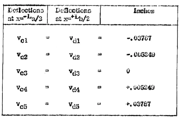
10-12 Deflections at Mdspsns Luo to Unit Moments Applied at B 5'^
; ■) ■?
10-IS flcduntisct Moments at Support B . . . . .
10-14 Reflections at Stidspasis Due to the Bedundisat Momaats
Applied at B . . . . . . . . . J'J
10-15 Beflcctions at SJidspaas of the Continuous Structure Under
the Uniform Load of 100 lb /ft . . . . .
10-18 A n g l e s ... 3~
Table 10-1? 10-18 10-19 20-20 10-21 10-22
10-23
10-24 10-25 10-2510-2?
10-28
10-2G
10-30
10-31
fo rm al Displacements . . . . . . .
Ts‘Msnrers&l Angies at at » ^ and itfc a »
Angles M x « ^ and a iK * - ^ a ...
Taugea&al Leads in toe Planes of Four birips Due to Unit
Moment; *»%v » 1 Applied st Edge b. .
Tangential Loads in she Pianos oi l orn- ©trips Due to Unit
2Aommt Mr » 1 Applied at Edge c . , .
Shear Stressed Duo to Unit Moments Applied Transversely
at Edges t? ead c ...
Botstlons at s * O of Plates in Span BC Du© to My = 1 at
Edge b and Mr » 1 at Edge c ...
Deflections at x * ^ fr ol Plates in ©pan BC Duo to Mr « 1 at
Edge bend Siy * i'a t Edge o . . . . . . .
Beduadams; Momenta Duo to Moments B y « 1
Deflections at Midspan e l BC Due to Bedundant Moments
Applied to Plates at B ... ...
Deflections oi the Plates e l the Continuous Structure Due to Uniterm Moments M j. ~ X Alternately Ap|slioci at
Edge b antic . . . . . . . . .
Normal Displacements to Each Plafce S trip Due to Moments
Mr ® 1 Applied st Edges b and o Alternately
Transversal Itotetion o l Plate Strips at Midspans of
Continuous Structure Due to Mr « i . . . .
Relative Angle Changes at Joints Due to U T = 1 Alternately
Applied at Joints h and c . . . . . .
fteduadaafc Moments Acting Uniformly Along the Edges b and
o oi the Cenflauoao Structure . . . . .
3 9 "> rv^ •IWVi 105 109 107
1 0 3
109
1 0 3
110
i v?
112
Tsfcl e
20-32 2'ioal EieHaetioaa cl &c ConiXmm.& Structeare Sue to a Uniform Load of 200 lb /ft Applied at Edges b and c
22.-2 Besulto of Strain G a u g e s ...
12-2 Beading oi MaJ Indicators .
21-3 Beading of ftla l Indicators .
LIST OF FIGURES
Figure
1*
O •M#
Contiuuoug Folded Plate Structure «
j&tot&od oi Aaafysis
Uniform Load is Xtoeelved Into tiao Hanes ol Kao Plates
4. Pinto i>m Uivdcr Uniform Load
5, Plate Cnsss-Six-Uca ,
0# Longitudinal Shears on Plate bm .
7, Strip Element o i Plate fern . . . . .
tiioment Area of Croas-Seefcion . . . . .
8. Volume Element oi Plate bm Under Lend
10. Plate m Under Uniform Load
U . Loc^ibtoiaal abeaars on Plato ^ . . .
13. Strip Elomont oi Plato am • « « » •
10. Plato gjgg With Unit iSorasoi at B . . .
H .
IS . Leagiisudias! Sfeenrs on Plato am with Unit Moment at B
16. Volume Element oi Plate bm with Unit Mor&e-nt at B
17. Plato 2jvj wlQi Unit Moment at
18. Strip Element oi! Plate ^ with Unit Moment at B
7 !*
19. Jiiorm&I BieplaeotriCitta vir m and \vm . . . .
F ig u re
20. licdundsat Bfomeat MV
21. itedundcn'c Moment Mr iiosoived into Forces Acting on
Planes o£ Plates
. . . .
£e&nitie& oi ihc Angular Siispl&cemeate w ^, v/^
23. Dala for A iifilyiiccI Probleni
. . . . .
24. I>ata for Analytical Problem . . . . .
23. loads liesolvoti into Forces Acting on Pieces or Plates
23. longitudinal S im rs
.
...
3?. iiotatiuuis at B L m to Unit Moment Applied at B .
? 'V*
74
7-3
: *»
.'•y
28. Angles S ^aad m . . . . . . . . ^
.Jtj*
98
101
102
± ’s :
20. Normal B ie g k e e m e a is ...
30. Betiuftdattw ^foment 20^ . . . . . . . .
31. Bctfttadant *ff &&»»«»& U v Bcsoivoe info Foscea Acting on
Planes o* Plates
. . . .
32. A m erica* Values o i 8 . . . .
33. Numerical values oi ^ ...
34-46. Photos . . . . . . . . . .
11 3-1 27
4?. Cros^ccettcu o£Concrete Specimen . . . . .
48. otrai^ .yoc»£d»».on . . . . . . . .
"I ■”;
49. itofc Up oi Gauge indicators . . . . . . , ... ....
30. Set Up «S Gauge l o c a t o r s ...
-■-
-j"'-51, Modulus of Alue& city of Concrete . . . n
Pigusre
32-56. Stress felstribatloa. fciagraais
i>7* Deflec&cB Diagram . . . ,
58. Eolation ot Doliec&ons Btso to and T^,
KOTATKj»
Note: A superscript © isciieatos that the symbol denotea & cpsctt^ caused by
uniform loads Snm o r U the letters a„ b„ o, d appear in the subscript
£h«g? sn^er to the tour spans shown in Fig. 2. The same tetters ore used in the
superscript to indicate the Mraixsr oi the plate; in the superscript those letters
replace the arable numbers S9 3, 3 — as these numbers could be eas%
cou-toscd with powers. I f the symbol hasn't any o i the letters a* fo» e — — in too
subscrips it* refers to the confcSisaous structure.
The firs t part o i Hite analysis is carried out under the assumption
that grates are hb^e*mm eeted by piano w ires. In the second part of the analysis
Cfcdnt displacement) the edfes# are made rigid by applying redundant moments
Mgy where the isuperscrSpt r dcRotes the number oi the edge to which the moment
is applied* These moments are resolved Into loads $Fig, 20, Fig. 21).
A ll resulting symbols carty the superscript r .
Sleight o i plate k .
La Length of spaa AB .
Lcogih o f sm a BC.
iviomont os plate am (Fig. 2) duo m load S ^ ,
*v4sa Monaco* ©£ plate fom (Fig. 2) due to load ^ .
SC'
I&L* Moment o£ plate am (F ig . 2) due to M » t at B .
“ t o
K?>
sm
& 01
w
a 9 > dm M'0323 Ng My „ » am
< ■ £ e W S »n S im "tss& *ta \ > > T sn
’ i or T™
v. am sm i crr:;, 9
V
-m i
Moment o* plato bm (F ig . 2) duo to M ^ 1 at B.
Moment oi elate am dae to shears T
Moment oi plate bm duo to shears T, .
bm
Hoiaj^at oi plato am duo to shears T »
cm
Moment oi plato bm duo to shears Y ^ n«
Ectiundaof moment (Fig. 2) at B.
Sfceariag sfcresses shown in Fig. 1. Tim euperemtpt o refers to uniform loads ©ailo she superscript (1) rotors to longitudinal shears
For eubscripto a, b, o, and d the reader may refer to Fig. 2
.
Shewing forces due to and shw> respectively.
J> Shearing forces duo to unit moment at B.
Uniform load aoitog; on too plane of plate am .
Unitom load acting' on toe plane of pinto bm.
Thickness of plate m*
LoogifcudlrM shearing stress between plato in , and plat© (m+1). For too superscripts toe* reader may refer to the note under Notation.
shearing constant related to T__, by equation (<E-3lS).ffw
R eflection oi plate am under the load £ .
am
Reflection of plate bis under toe load .
Reflection of pfeto am cato to unit moment tit B.
Reflection oi plot© b ia duo to unit moment at B*
Armies shown in Fig, S.
Ijf Boi&tion oi' plate am due to S .
am
Kotatioa o i plato fern due to S ^ .
“W j Botatlon a i piate am <Suo to unis moment at
Botatioa oi plate bm t$m to unit moment at
Angles shown ia Fig, 3.
CHAPTEK1
INfB G EU C llO N
The prismatic folded plate structure (Fig. 1) is formed by a series
of adjoining thin plane slabs mutually supporting each other and rigidly connected
along their common edges. They are usually closed off at its ends by integral
diaphragms. Even though there are many folded plate structures made out of
plywood and some out of m etal, most of them are made out of concrete because
it can be easily adapted to different forms.
In reinforced concrete the unstressed m aterial is relocated to
areas of fo ller utilisation thus making a substantial reduction in concrete per
square foot or surface and making a substantial reduction in dead load. Floor
and roof systems can be shaped to accommodate ducts and u tility troughs
thus obtaining more economy as compared to conventional structure. Folded
plates have advantages over curved shells because of the lees expensive
framework, easier concreting and screeding. sim ilar advantages exist over
more complex structures such as arches and fram es. Because oi their
stiffness, folded plates can be constructed over long spans without m increase
in m aterial requirement. For these reasons, in the last decade,folded plate
construction has found increasing application fo r rooi'o of industrial Liildlage
1
h i
n
1 q
!> . ,
i \_
it
CO
~ 7 \
Reproduced with permission of the copyright owner. Further reproduction prohibited w ithout permission.
and hangars as w ell as for the aides and bottoms of elevated bankers.
The methods oi analysis oi folded plate structures msy fo il in the
following four categories:
(a) Beam method *
(bj Folded plate theory neglecting relative joint displacement,
(e) Folded plate theory considering relative joint displacement, end
(d) Elasticity method*
Within each of these categories exist many papers using different assumptions
and procedures. The form relative joint displacement denotes the displacement
of ooo longitudinal side of a plate with respect to the other longitudinal side.
The basic assumptions In the above methods are tho following:
1) The m aterial is homogeneous and linearly elastic.
2) The actual deflections are relatively small as compared to the
overall configuration of the structure, lienee, equilibrium conditions for tho
loaded structure may bo developed using the configuration of the uadoflected
structure.
3) The principle of super-position holds.
4) LfcEg'itediaal jo in ts are lulls; m onolithic w ith slab acting eoatitjuofoly
through the joints.
5) Each aappyraag dnghrsgm is infinitely stiff parallel to Its owe
gtoi© to t Is perfectly SejdfeSe normal to its plaao.
Beam Method.—3s th is method the sfcructero Is assumed to doUeci
in such a manner teas a ll polnte in the same cross sections deflect tho seme
mnouaS* Cross oss6Eoiistt however, tend to spread cut coaaklorably (Fig, B7)
when tho Salmd plate structure is loaded. The beasi theory &my ha applied
w&au fe@ folded plat© stm &tyea ay© stii&saed w ife is&eyaietfiMa ty&aovGi'se
ribs ypcced sad designed, so a© so maintain tho s&ape oi' fee structure.
Sfolusxl i% t£ Theory (with and without relative joint displacement).
In both ©teases of folded piao® th m rj few Svn^^wSital supporting action ef each
pla&i f.a governed by beam iksory and fee ivmsvmtm aapporfeag notion is feat
os a continuous one-way stab. Vvaen fee boom theory in each plate la adopted
- fee £oftowfe£ assuEapikioe or© i&pttefe
1) Longtfectaal ©treaaaft Is each plate vary feoayfy across fee width
e i each plats but fee ixaosveree rate of variation ol agrees mop he dilis-roai in
fee various plates..
It) Membrane nfecasing staresoes in each plate hove negligible
•yfifeot or fee desisetion ox fee siruefcre.
3) Keirmai s&res&es in each plate fe fee tsm&v&em direetioas or©
iu 3$alibrknn co^derataosus but have »egl%tblo eHect on fee deflection
o i fee styaehire.
By adopting fe« one-way $!<& setloa fee allow ing assumptions aye
taiplSofe
4) Slab ba&isg is essentially cue wey phss&meneii cecurrliag is
fee- transverse direction; fee oSfect o f longitudinal slei> bonding is negligible.
5) ladSvisfesl. plates possess negligible tQr&loml resistance.
Toroional stresses d ie to tw isting o i fee plates as w ell as ^eftsctSons due to
feeec* stresses m ay he ignored.
S) Saciial chearsng stresses (normal k>. tho slr&J have aegllnibSo
effect ©a the defioctton ©i the structure*
For norm al span length to plato width ratios assumptions 1 and 2
do not Introduce any substantial inaccuracies. As the span-width ratios become
sm aller* however toe longitudinal stress becomes non lin ear and the shear
deformation becomes snore pronounced. Assumptions 4, 5 and 3 deriving from
the use o f one-way slab theory are sufficiently accurate fo r length-witito ratios
greeter than 3 and widtis-thicJmeas ratios greater than 5 (10).
Folded P late Theory Neglecting B d ative Joint IStaplacomenta. ~
fa this theory I t is assumed that the changes In transverse bending moment
and in foaf^tucLoal stress due to relative jo in t displacement arc negligible in
comparison w ith tho values o f these moments and stresses computed on tho
basts e f no relative jo in t casplscements. Investigations (20) have abeam, how*
ev er, that Joint displacements are too significant to be neglected and must
be considered in analysing folded plate structures.
Folded Plato theory Considering ft elatlv® Joint l^splacsme&te.
'fid s theory is based on the gaiescal aseumptiona which have been previously
described, and takes Into account toe effect of relative cSspiacemeni o f toe
joints on too transverse moments and membrane stresses. Some of toe
practical methods of analysis arc mentioned below.
1) Vhwssew’a Method (28, 27), This method determ ines too values
of too stresses a t c ritic a l sections in toe structure by too solution of a m t of
simultaneous Unear algebraic equations that arc established on toe basis of
equilibrium at toe c ritic a l section and on the basis of continuity of Joints
transversely. Longitudinal variation of applied loads and transverse momenta
arc approximated on the basis of a Fourier aeries.
2) Portland Cement AbsocIbKou Buliotia (24}. The analysis con
tainer in this builetia Is sim ilar to that of Vlassow. The Epical equations
Involving the unknown stresses and meajiaats are derived for the ease of usilonn
vertical loading on a simple span structure. The oulletia contains a table oi
design coeffteieata for the V-lype folded plate sm*ctare* Bn&msion of the
development to other types of loadings end support conditions la not covered
although it is examined ha a gm arat way.
3} Gaoler's Method (10). Gaafar used the principle of super position
to consider a folded plate structure actually loaded between and at the ridges
93 the coitibinflitioji of fa) m Mtontieal structure loaded between and at the
rtdgea hut exported at the ridges against deflection and
(ft)
m
identical structureloaded at the ridges only by dm rl<%© reactions of tho structure in (a). In
developing the theory fo r the folded piste structure (b), loaded at the ridges
only, be motees the assumption that the elastic curve of deflection duo to applied
food is the same as the n ormal deflection curve of the structure (half si a©
wave &>? simply supported structure). TMs assumption Is accurst© within
approtf mately 2% fo r tosgitudlnallsr &ym uatrical losin gs. The hall sine wave
concept m tho deflection curve is in e rro r fo r loading that is largely aa*l~
ayima&tric longitudinally.
4) Titsh&ki*® Method (31). Yitafeairi present several methods c i
aaslysla with major emphasis on the so-called method o i particular loadings.
h i this method ho uses tho principle of superposition used by Gaafar to aaafcrsse
the etractare for tho actual load oa it, assuming «uy*elciag ridges. The reactions
deweSftped by t&Bse B&mm-zd feat actually noft-i’oxtefeaxt supports arc the© applied
as lougitodii*d ridge loads which are carried a». each ri<%c by te© plaice
me«si-\n$. at each ridga. The resulting aeUecttoaa of the platen are converted, on
the basis of geotnctrieal ooniJidoratlons, into relative joint displacements which
are associated with tr&averso bending sttosxisnts is the elabo. From these, a
sot OK ridge loads,- caSIal saper&ottR loads, noees&sy to snaSattin the deiloctod
shape of the structure is obtained. The structure is ikon subjected in hum to
several appropriately chosen, imtopoaticnt ridge leadings, These loadings
are aash m ultiplied by m ttodetermiasd constant sad cosnbfcoed so as to eliminate
tho preceding suporausas taoiUng at each ridge. 2a this process h**2 aim
ul-taneou# equations each containing the &-3 undetermined constants are obtained
and solved to evaluate the constants. Here, a equals the cumber oi plates.
W ith the Constanta known, the controlling stm saeii and deflections are readily
obteirafete. Tho assumptions sad epproxlmattons used by Yiteheki are the same
as those used by GeM sr, previously described, C o n fid e n tly , YUsha5d*s
usual procedure la subject to the same lim ita tio ns on applicability as Gaafor'a
theory.
E la sticity Mt&xxL Ctob&KiTg and bvvo developed ilt y n solwttcn to r
the otraases in a folded plate structure by combining the equations o£ tho plate
theory to r loads norm al to the plane o f the plates aud the elasticity equation??
defining the plane stress probtam to r loads in tho piano o i the plates. Applied
tam ing l» approximated by a F ou rier series. This method is applied, where
component plates o£ the structure are relative ly short compared to the width, and where teoaslatiou oi individual jo in ts is com pletely prevented.
8
Tho theory presented is this paper tor continuous folded plate
structures la developed from im &ge's theory for simply supported folded
islate structures which he outlines id hie book published ia 1962. Hia theory is
particularly attractive since the daflaotSoiia of plates are given by a diffcreatlal
equation which can be generalised for ooy toathng condition by expressing the
load in a Fourier series. Ftllgge'a solution of Joint displacement la very much
sim ilar to that of Yltehakh Chapter VJ0 of iMo paper presents the method in
detail and extends It to continuous structures, while Chapter 111 describes die
method of analysis by which FlUgge's theory is extended to a continuous structure.
Chapter X I gives the experimental results of a continuous concrete folded plate
structure subjected to uniform load.
CHAJPXJEH XX
ISSTO B IC A L GISCUSSl&JI
_ G. £fclers(6) wrote one of the fleet papers on folded plate (boor?
in *036. Eh. (e re proposed & foldechplate theory based on linear variation of
longltadiM l stress in each plate hut neglected the effect of the relative
displace-m eeioi the joints, In 1932 E. Gruber (14) took approxidisplace-mate account of Joint
trtmalatioas ami rotations fcy using a atrip theory approach, A further rctiao*
meat of the membrane theory waa made by a , Craesmer (2) and Gruber (19)
by considering the actual atrcsc dlatrlfauttee* in the planes of the slab. In 194?
the method was introduced in the U .S .A . in a paper by George W inter, F . asce
and M , Pal (SO). Their theory neglected the relative joint displacements but
dsvolopeci a convenient iteration procedure to determine the togituGinal stresses
patterned after the moment distribution procedure.
The relative displacement of the Joints which waa firs t proposed S$r
Gruber and Omening in 1933 (14, 1?) was considerably sim plified by w . Z»
VIa«3ov?, 1936 (28) by using linear algebraic equations to calculate the
longi-feidtnal stresses and ridge swmmte at c ritic a l sections of the structure.
IC. Girkmac® and The Portland Cement Association (12, 24) submitted methods
sim ilar to Viassow’o. The theory involving relative joint displacements was
9
10
also developed by 1„ Gaafar, Ivi. ASCE and I). Yitzhaki (21, 31). A . v>er£el amI
$bm J. Ei Goldberg and H, L» Leva (29. 13) developed approaches that considered
both two-dimeaeional elasticity theory for doterminnttoa of membrane stresses
and tm way slab theory fo r determination of betiding and twisting of the slab.
In 1962 FUige published bis book In which bo outlined the theory which was used
In Ibis paper to develop a method to analyze continuous folded plate structures.
MET3DK OF ANAMtOS
Plate strip m, bounded by edges sr»-l and m (Fig, 1) mid subjected
to the reaolvod uniform loads ami S ^ , is muJyjsed as a continuous beam
supported at A, 0 , and C. The continuous beam AC is then divided into two
simply supported beams AB and 0C (Fig. 2b). JDue to the uniform toad 6^
plate BG rotates 0 ^ dagrecs at end B, while plate AB, due to the uniform
toad rotates - degrees at end B (Fig. 3e). Sim ilarly deflections
and are produced.
The relative rotation of tangents a and b is 0 ^ - 0 fi. In die
continuous plate AC, however, the tangents a and b form a straight line emee
the dofleetioo curve must be continuous. It is , therefore, necessary to apply
a set of moments $5*,^ at ends B of pistes AB and BC which w ill produce a
relative rotation equal and opposite to 0 ^ * e nr;1, where r in goes
from K * 1 to K - 1 ami K » Kambor of plates. The efcrossee and inflections
duo to die moment Mom would then bo added to the stresses and deflections
prcdaccd by the uniform loads and S^n . The resulting stresses and
deflections would be those o i tbs contlmoas plate AC subjected to toads
and Sjjqj at spans AB and BC respectively, The moment however, is ®fs
XI
12
unkntrws quantity and must be found.
At ends B of plates AB and BC a unit moment 2s applied which w ill
produce rotations ecna» 6 ^ and deflections and (Fig. 2d). The
relative rotation between tangents d and c is — e . Umc®
* 4 d ° f o -~ f o *' • *3-1)
eam " edm
The stresses and deflections ol the continuous plate can then be computed. Once
these Btresses and deflections have been obtained Joint displacements can bo
considered as described in Chapter IX .
Computation o£ &
It is assumed that the edge loads are vortical and uniformly dis
tributed la the X direction. The load at every edge may be different in magni
tude but It must bo uniformly distributed along x throughout the whale length
a i the beam.
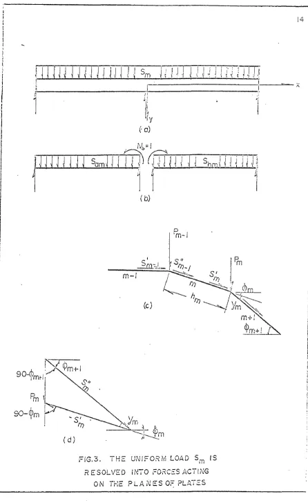
FiUgge (8) resolves the load Fm acting cm an element at unit
length o£ the m -th edge info two component is the directions and + j;
■■«&■- - . C » + P 008 0 m (3 -2 )
m iu . w m m ---— —
eta rm sic y m
These loads can be carried by the strips m and s» + 1 respectively (Fig. Sc).
The resultant load acting on plate m would be
»» *'
b » i» . + S . (3 -3 )
m a - 1 m * 7
A
JUU ' \ ^ m •I -I
Lr
P LATE m
I ..
I
(a)
_L1
L
U N IF O R M LOAD
P L A T E bm P LA TE am
cm am om
Ve,
( b )
UNIT MOMENT
cm 7dm dm
( c )
Mo = J
( d )
m o m e n t d i a g r a m
FIG.2. METHOD OF A N A L Y S I S
14
s
\ i m i i i 11 j n 111 m j .]
h
( • a )
trim
(b)
‘mm
-( d )
F IG .3 . T H E U N IFO RM LOAD Sm IS
R ESO LVED INTO FORCES ACTING
ON THE P L A N E S OF PLATES
CHAPTERIV
AHAUB5I9 OF PLATE ^ UNDER UNIFORM LOAD ^
Bending Mom eat Due to
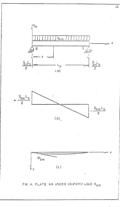
The beam shown in Fig. 4 (a) subjected to the uniform load
fyas thft hanrBiffi yn<tmnnfc
»»g* <4-i»
Shearing Forces JDas to
° { & - ' w r f * - * - <«-2>
Let uanow aBBumo thai the ^late strip is Blender, that is,the height l&
much sm aller than the length 1^, thoa the beading eireas crx and the shear
stress "C- may be found from formulas of elementary beam theory. More
over, le t N^ =* tm and « T j^ whore is the thickness of the plato
;. 3) . Ilestoe
« x L a
(o )
er T t « VAy e ^ ^ blK
m - 3^ “ - t# 5 # * <4- 3'
Q bm ~ ¥**) t^*31 + 2 ( l T ~ 4 ^ (4-4)
i»«ym--- * T 1 5 ar~w
I T ®*n hm
Simflifyiing the above equation
" - f r ( I - £ ) • |4 ' S)
IS
a ! IS
Pm
m i . J , <$bm 1 j i 1i V V ' J JJ
?
A s
////
s L.Dm b
U
( a)
c_c
////
S L
b m b
-b
L b
(b).
^bm L b
bm
( c )
FIG. 4. P L A T E bm UNDER U N I F O R M LOAD S bm
I
17 j
i
s
i
{ \ ii
»
i
t
F I G. 5 . P L A T E C R O S S -S E C T IO N
i j
i
)i
10
Also the stress
toon a m j^T ( W )
A t the lower edge oi the strip m « + i*p .) the normal force
*0)
*ta m P *w ta o « tt« « tw ^
* *■ » ’ S *» ^ <4_7>
Ami the strain at the upper edge o£ the adjacent strip is
(o)
e
S
U
f
f
l
•
- 7 ^ - - — • «-»>* ' TED + i * % + 1
&tao& the two adjacent platea are connected to one another these strains must
be made equal to each eS&cr. When this operation is done the two strips w ill
exert forces upon each other. These additional forces are shearing forces
Tto acting on the plane o£ both strips. These forces are shown in Fig. ? acting
in a positive direction in accordance with the sign convention for ft*., (Fig, 6b)« Jay
From Fig, 7 it is seen that the edge shears w ill add an additional
moment M ^ to She bending mom out of the strip. An axial force Is
m m m
dtso produced. Applying the equilibrium equations to the strip dement shown
i n Fag, 7 the following relatione arc obtained.
(1)
■ - *
bm i l>m
* T. , T. (4-9)
tix
V {1>
‘- 3 B * - ¥ « W i * ,w * « *
F I G . 6 . L 0 M 6 J T U D I N A S H E A R S i
IN E. bm DUE T O U NIFORiVi LOAD |
)
20
(Tm _ , ) d x
* m' + d ^
(I)
Nm
FfG. 7. STRIP E L E M E N T OF E. bm
!
I
I 1
<
21
Tha shearing forces mast
bo kaown in terms oi
xbefore (4-8) and (4-10)
can bo integrated.
The shearing forces
Tmproduce the force
end the moment
m
which
laturn produce beam beading stresses from which the normal force
,< M _ W lJ S A 1 2 u jM
bm
and
the edge strain
CM
uU)
6 ^ - S i - ♦ “ t o y . (a-ie j
E*m
E*m
Xn equatUm (4-12) the second tern on the right side is negative if y » -
h s iKs 2
end positive if
To avoid discrepancy of strains between connecting edges the
following condition must exist.
e S . + e S m ” e i$ » n > ♦ € £ U i > <4- 13*
A
After having
substitutedaspreeslo&s for the
Os♦ (4-X4)
® **0 E *im ^‘ra E *m *l ^m+1 E *m+l ^ru+i E W -l ^ m +l
E lation (4-14) is the coKipatibiUty equation from which on equation ter the
unknown shearing forces
can be derived* After differentiation in respect
to s„ equation (4-14) yields
<4-15)
£ ^ * 0 5 ^
6 iiS t e ± i) d Nb fr+P 6 d Mb to + ll
CM. <fe dx
^ fcm+l ^ta+1 ^ *m+l * W l ®* Sn+1 ^m+l
Equation $4-1) So differentiated In respect to x to yield
l | L t t = ^ ( L b - 2 * ) . <4-16)
Equations (4-16), (4-8), and (4-10) arc substituted in equation <4-15). After
ainapliacatioa
■ U lV +2T , J
*m
hm* » W l hm n
* “
^ +1>
_
V
i T
2^ ,
* W u S - * <--- + —
— ----
(4-1?)
*c ; t» ® V l W
A total of (&-1) equations such as (4-17) may bo written for every edge from
sn “ 1 to m ®
K -l
(aorder to solve
K.- 1 unknown functions
X ^(a), since in
equation (4-1?) both terms on too right hand side are proportional to
(1 ^-
2k) „St
m a ybe said that
t (*-1 8 )
*b|m+ll® %(m+ l ) ^ " 2x)
whore T , Tm
+
1
ar© eonstento.
Expressions <4-16} are substituted la equations (4-17). The
result-log equations are then differentiated in reaped to x and sim plified to yield
«
a sot of ordinary linear equations for the unknown constants t m»
b(m+l)
<•*. an,
as * .n f t g a . ( . . u ,
^ior* W l ^iia+i
The Bending Moment Booultont
The moment of the strip <hte to the uniform load and the efeoaring
force Tm may he expressed as
« b m “ » C * “ t o
(
1
)
The moment is found by substituting expressions (4-18) into equation
(4-10) and integrating in respect to au Hence
<1K§S, b
dx - f L<Tb m -l + , t a H H . - 2 s » l4' n >
*bmH V * A + € (4-22)
*W bm
substituting the boundary traditions
m
x ® 0 Mbm “ 0
(1)
’“ H “ bm
into equation (4-22) it is iounti that C <= 0. Therefore
^5bdt - ¥ f r L - i + i h«> x - x2)
^ ^bm ~ ^brn * ^fcm
JKoqcc?
* - **> + j£ ( T ^ *
tM (
x2 - L bx)
(4-23)
Tlia fehoar Stress B e a rita a tQ ^
Tfc© total ©bear stress resultant q m « Q ^} + . Bat ® o
since the shears Tm don’t produce any vertical shear component. Therefore
^bm 'sSb m < ^ ‘ Jd <4-24)
The Normal Stress Resultant N.
The total norm al stress resultant N}>yvi » ♦ N ^ . But
idoce the uolfiom Itoad does not produce any net ibrce in the ae-ttirectioa
a t a given cross section. The N ^ . » . Equation <3-10) states that
** ^bm * ^bCm-l) * ^bm
dx
d N ®
- n f “ ” f C - i » - T L )(Lb - 2x>
Nt e “ < * L r l ' TL > 0 * " * > * * C (4-36)
Cl)
at s «* O and at k * 1^ » O, Theriore C » O.
N b m ”
K tm -l)
' T L » ^ ^The ^tresr. Besalfcant N ^.
From dementosy theory
G“ a £ . t JS&.
Si A 1
25
« t CJT
fe» aa bx
iii x • f t n ^ ll.,,^
KtoJ h
m : ^bO n-M * Tbm> V “ia "bo < m. i r T ^ )
(4-2?)
(4-sa)
Sbcar fetffeas lissuJltant M
ssv
J5W * J4s(y +M b v
jo y z (0) — a q
J&&
j « l » t hS
12 m ib
< * * A y ^
K
(
basy0)
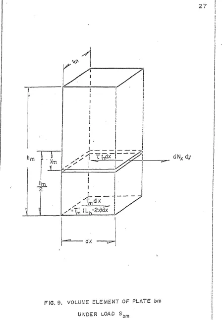
To fine) tbe element sbo’sm la iig . 9 te considered .
frm 7 2
X b tm l22E“ TbItt - 2 k ) 6 x * j ~ d N 7 ' d y
n . * K.-WW. _J_
(
1
)
(4*29)
(4-30)
(4-31)
(i)
Eillierai^atinjg J } ) in respect to is and substituting for ^i^E? acd »
•’ d x i s
the following equation is obtained.
j GC5£>4
I K t ^ s i B m w a g r e J S O ^ L f f c iiii!
F I G . S. M O M E N T A R E A OF
C R O S S - S E C T I O N
2 6
n. a.
2 7
dNx dy
FIG. 9. VOLUME ELEMENT OF PLATE bm UNDER LOAD Sbm
J
® (H j - 2 x) I i
* - S <5W - l ) < T bn!> » “ » (4-32J
"fcl
Equation (4-32) is substituted into equation (4-31)» which is integrated in respect
to y anti simplified.
Nbajr" <2 » o + V « • ' » * V * * »b. + V
“* 4
Equations (4*33) and 4-30) are substituted into equation (4-20).
I
* W * I 2a,<hm - + S j f U d h i l A s * m-ba ) <a W
m m
tL < 4> - s*>
+ _KK^ — tBym+ - *»*») (4-34)
* h m
The normal force Ny In the direction o£ the axle shown in Fig. 6(b) is
rather am a il and there ia no need to compute it.
flotation of Plate JSC
The deflection of plate BC ia subject to tine differential equation
12
— r * “ - — — 3 Mbm (« 5 »
<iK
t t t a v
The moment ia give/i in terms of in equation (3-23) which is sub
stituted In equation (4-35) to yield
= ^ , 3 **> *■ % < - 1 + *£>> <*£ - *1 ,*> ] ^
20
I I Integrated once in respect to k, equation (4-36) w ill yield the elope of the
clay tie curve.
12
£
L
£bm Lo ^ . sbm*S* hm a : h . . + T 1
»* **' —y —— .■...0»- —~g> ’ EKpn-l) om '-g + C
Lh■ ■WflllH
(4-37)
at s ® 2SL €» * O . (4-38)
The boundary condition (4-38) is substituted in equation (4 -3 7 ). A fter
eiciplilicetloa
E k*n 24
$ 3 -T
~ (T iL + T 1 ) H>
. s bsn-l bm (4-39)
The Integration constant (4-39) is substituted into equation (4-37) to obtain the
equation of the slope of the elastic curve,.
X8 Jujj a?
«wm m imrnJhrntm—mm
.. 12...
^ W © *
^ ^na^m 24
- - J &
% i 4 . hai ^ I i * x * ) —»i l
_ *>j<i *» n* — to _
ffenJjfc _ f e ,( T J -8- Tl ) ^
m -1 m 12 J
)
(4-4))
(4-41)
£&&$!&& o t^ M o BC
In order to Had the equation of the deflection curve of plato BC
equation (4-30) must be tategrated twice in respect to k,
fcfotti % aF _ **?»„,£ .c. ,t,l w ^ 5
-* W ,'t >v & t 3
+ Cx + D
«. '"bm + ^TU/ri<^ ^ /pi i ^*b n .
412 “1 5 y ^ C m - l) *Um>< 22 — J
(4 -4 2 )
so
The desleefcion 'V j^ . « C at k » O sad at x * /ipp lytiig these ooadslioas to
aquation (4-42) it Is found that the Integration confitonfc D » 0 and the iaiegr&itoa
constant C is lbs smi.e as that given by equation ( 4 * 8 9 ) , T b s values ol C sad
£ {# 0 substituted hack Into <4~42)» After sim plifiesilca
2* ** x (4-43)
CBAX>T£B V
A M L Y m OF PLATE m i U m & i UMFUE2& LOAD ^
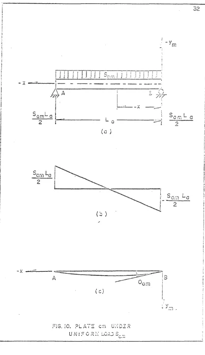
Pl&ta am shown in Pig. 10(a), is analystcd In the same 's/ay aa plato
0re
fem. Moat o£ the resulting equations correspondingly the same as those shown £or
plata tan whlia others mcy ahow some differences in negative and positive signs.
For S ta reason explamttione and derivations of equatiaaB have been omitted in
fchiaaocttom The reader may rc4!or ttoolc to [dato bm for more detaUa.
EkmdijOK Moment Due to % *.
Tivitu
^arn * ~sam
C5-1)
Shear Forces JDuo to
The reader mcy refer to oquattons (4 -2 ) to (4-6) for more details.
Lon^fttdlaal fsfoear Stress .Lcaattons
The main equations used to develop the shear stress equations ore
31
32
m
m u .
i i
t S r , - ,
- . 1 1 i j I J .1 1
1 i !
•j . ! !
i
--- --- ---.
S L
^ a rn 1- a
L
i 7?T
u n;
(a )
Sam *-Q
A
am
m .
FIG. -C. P L A T E U M! :
G.Ti
O P* ;V. L . 0 A 0 o
OW'D 1 3
shown below. The reader luty rei’ar to equations <4-7) to (4-19) to r detoito.
<5-5)
e ,B>
„ g ^
am'i ;',2'
AO) G
o jb s-h ) - r r ® ^ M
*■ jsj+ I £ in i + A
“ V # * Ta a <“- «
dx
dM am ” ~ ^ (a m -1 )+ Tam^ C8”®)
dx
J l) 12 M v
N««&
“*
*“
+
^ ym
<s*d)
^ *&
6 ^ w ^aaa.... + ^ - -r
£ **&**!»
axm
e<°> +e w - f w
♦ f «
axso asm ^aa(m +l) ^Aaa^s^l)
i f C +
C
. 6 u < Zii4 m J|ni
<S-10)
<S
ft»,7e bW
a t e t a . + _ « e i a _ _ _ J s t e a _ _ (S. 1S)
m fcWlfep»»
1 W t iteH
“ W t
SaH
a * « t i S g »
r». .
£j i^,«
-j t o ® .IM
il )(W
l I «
dx dx , dx
® hn E hn tlm E tns ^r.
d il;W M d „ u Ma(m n)
<5* &s
^ + „ _ _
E
■
“'%** i
E ‘
^•1 kj»+l
t jj ^ A» (» i“ l ) * 4 + t 2 T u (m + i) ^ a n a 4* ^ i&+ * m>- i
$ %ro ( ^ i + %*b + 3 C^s + 2 »)
*%i Em+t
T 35 T * (*-« + 3 *)
* * ■ » 1 * (5-15)
W l ) ° r a(m +l) <La * 3x)
-.mll l fw — (T^#„ |J <•§ I .—I— . + ..— .A— .1— i rj»l + - ■...L ..— ml
tjjj hm ^ *m+i^m+1 ^ ^ *
*
l ik a .
4
-
ISatsa&L
<5_16)
ha %» *m+i ^ e + l
The Bending Bomeat KesuUaat l i am
The reader msy refer to equations (4-20) to (4*23) tor details.
Siun “ » L * <9* 17>
am
—■asy. » - -*«•# y . * T ) (5-15)
<3x 2 o fm -l) *am ' * '
(
1)
2*5 a _ , » + T ' ) ( L +2?r ) (5-18)
dx 2 Ji(jn-1) srnr ' a ' ' f
m£> « - 1k + T j ) (L x + x2> + C (3-20)
am a ' a(m -l) am a
(1)
Tiie moment M ^ ® O at x *» 0 and at x « -L ^ . lienee C » O
«* - + y 1 ) (l
am 2 a (m -l) am s
•?
x * x*')
3 5
Reproduced with permission of the copyright owner. Further reproduction prohibited without permission.
C
JN
D
E
R
U
N
IF
O
R
M
L
O
A
The Shear Stress Besuifcans SJtt
The reader may refer to equation <4-24) for ueUuitt*
(S)
^sia * ^ « n * ^am. (5-?.S)
4 ° ^ - - 8m ( La + x) <5-24)
(1)
- O (5-25)
^aitt Cl “ + ^ (6-20)
The Normal Stress Baeultimi
The reader may re fe r to equations <4-2® to (4-26) fo r explanations.
(0) (l)
Nam ° Nam + Nam (6-2?)
N *^ » O (6-28)
(1
)
d i t ' A .
S F * * f r a (m -l) ' TL ) (L a * 2 < 5 -^
S2 > * <S‘ (m -J) - TL > ^ * + « 8> + c «*■*»
,<«
mu ~ ... 'a ’
Tbs stress N ,._ **. Q at x *» 6 and at s * - i. „ . Tiusrefore, C » 0 .
M«m " *r a (iji“D * Tam* ^*a x + a 2) (6 -a i)
The Stress liosultant
The reader may re fe r to equations (4-2?) to (4-28) fo r esplaoafciofta.
37
asm
£m
SL ^aoa
2
<ta s 5 * j r )
^aaa» “ Sn ^axm
(6-32)
(5-33)
N
axm i f Tam + 1 2 » ^ - D ^ L *
* L
(5-34)
sfooar stress Beealtcafc N^am i
The reader map refer to equations (4-20) to (4-34) tor explanations.
(5-35)
M
(
0)
(
1)
N »W + K
aym asym aaym
d M
Naxym * Z ™ t^am *to
am
<£
»■
.w-axym
N.0axym)
1m
2
(6-36)
(5-37)
(5-38)
dx * T l (i* + 2 x ) d s + <ftr (5-33)
- '-am m am a / asm
M
(!)
asm
m
^am + X3 y ^ ,
3
h,m
"a + 2s
(8-40) h'm
asm (T a(m -l) - r|m > * * T l i’am) y ds
(5-41)
38
11) Tam *La * 2
Hasyin a 4 ^ *2 y*n * *W * ^xo ** *W
T * ^ (i- +2x)
♦ --- < 2 y f f i - V < 0 ya ^ V < ^ >
3 Sj N
4 hl2m_.
C 2 yjjj+
hm)(6 Jfjjj *■ hj^)
i ^ y m V ^ + V
dotation of Plato BC
The reader may refer to equations <4-35) to (4-41) fo r esplanations.
(5-44) _ .T ,12
H a C “
.2.
d » _ _ aaa _ •***12
dx2 & W 4 L 2-® ® (L s + ^ « -S . 2 * 2 (talso-D \ + T1 ) (L x + x2)am' a ' (5-45)
d v am = .
'* Vr axu'i
to t H o f f c
- W / V f +
xi )<V ‘ *
O 1 2 u / <5 j •' sjb - • rf r,■ ’ + C
(3-46)
Gfc K « "g" e = 0
c =
XSm La + hJ V l ) + Ta m ) La <5-4fl
o&
&
a
2
x2 \
T 7 “ 2 ( f 1 , aim "!) « + ? * f r * — + J*3 )a m 'r ~ ^ L
2E
Saa L
S .. 2-f ♦ k (T * -♦ ) I,3
2a o at *(m -l) am % (5-48)
= J U L
a M * * * a(m -l) am 6 (5-49)
^Si§SfiS!LoiXiS««Be
T l» retu & r may re fe r to equations (4 4 $ ) to (4*42) fo r explanations*
2 E tm i F ~ r Si“ (* * * ■ * * * * > ■
-* -* )]
( 2 ^ * + l^ )| + C # + C ( 5-3C)
A* x«o and at x »-La r ft<tBrt » O* Hence D » O and C has the same value
as fiiacwn In equations (3-10).
V ** •
v a>a» - * — — a * 4 *
2 E4m *>m L
aLa x - l*a x )(S ^ * k jts ^ ^ a (m -i) * ^ a ® /^
(S-51)
4 0 !
m
r
3
T n - i QX
'mdx
!
t
dN,m
FIG . 12. S T R I P E L E L E M E N T OF E am
UNDER UNIFORM LOAD Sam
CJiAPTEB VI
ANALYSIS O f PLATE baa SUBJECTED TO A UNIT MOMENT AT B
B$adi»g Moment Due to M *
k. __ ____ ora
A unit moment is applied at the Bern* ot plate m , span BC»
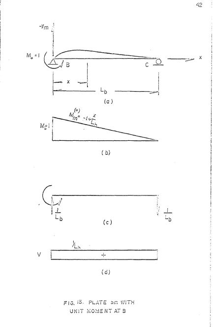
as shown in Fig, £3 (a). The bending moment in the plate
10) r
Mdm " “ 1 * ^ <f>1>
Where the subscript d In M ^ r is used to distinguish this moment irom
i&ir /a ir
and which w ill be introduced later. The (super script r indicates
the plate to which the unit moment is applied.
Shearing Forces Due to M *m
<j°> m - i m
■'Him ' . ; - y , l- (6-2)
X X f'
feince, as mentloned in Chapter IV , bn1 is much sm aller than Lj>»
the bending stress and the shear stress X may bo found irom
elementary beam theory, and so may their products with tm. . ,,(G )r
N(0)r „ -w o * * a I g W . Ay
djQrm ha dx 1ST
+ V ( l P - y d ] i »
* am’ " i-"mi “ \ -m ta
?4dxym --- — — --- r--- ' "}
T g *323
42
FIG. P L A ; E iJi~j VVJ i H
U N I T M O M E N T AT 3
4 3
( J L ; (C-4)
dsym u3 \ 4
m
Aisc ifco stress
/ ,r .
<a. 6)
dxm 75 'u
m
At the lower «3ge of the piste (y fflc 4- ^ ) th: sormal force
C&>
Mdaan P**0*^ *33 strain
(o) (o)
^ - iiJ S ffi (6-6)
0X413 ^ * *mfc&
said the strain at the upper edge frm+1 • -^jg+l) of the adjacent atrip is
m _ (
dx(m+I) v t .sT (6-7)
" Hn+i“jn+i
^ince the strips are connected toeach other* these strains ought to he equal.
By making the strains equal the two strip s w ill eascert forces upon each other.
r
These additional forces are shearing forces acting on the plane o£ both
strip s. Theue forces are shown in F ig. 14 acting in a positive direction in
accordance w ith the sign convention fo r N (Fig. 6 b)»
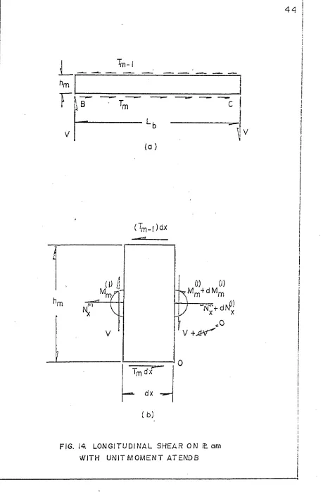
From Fig, 14 it ie seen that the moment caused (by the longitudinal
shears is balanced by the moment caused by die ve rtica l shears. Hence die
( l) r
moment M =»C. Since the un it moment is applied only at one plate* say
■m-(a )
m in
V
( b )
FIG. 14. LONGITUDINAL SHEAR ON (Earn WITH UNIT MOMENT AT END B
FIG. 15. LO N G ITU D IN A L SHEAR ON IE. am WITH UNIT M OM ENT AT END 3
i'
I
\
46
th e c & 4 < m + l) F r° m F' 9 14
J M
CIS
$ m T , (3 -8 )
*04115-1) dm ' '
Vcls * + T n 5m. d * r d K ^ + T . ^ 3 . cix
d (rn -l) g *■ cm dm 2
1 “ v * . - - f d c ^ - a * w <1K
«fa
= % f f , * T ,. ,>) dx - !k (T « ... + T , )tix
u dt» 2 d m d ( m - l r I p d < m - l ) el m
d M * * 0 <6-i»
dm
The Shearing forces Tdm mmt be known in term s of x before equation (6-0} can
be integrated.
m
The shearing totem, T .^ produce die force £rcm which die
normal force
1»
M
V
sivi the edge strain
w«»
f W « ~$sa— 46-xi)
than K Ssah^
The strains between the two strips m and m * I are made- equal by
mo follow ing relation*
£<°> + £<*> e £<°> + £<1) (6-12)
dxm dsm dxm-Kl dsm *l
Vrfcer© in goes from 1 to K. A fte r having substituted ospreasloas fo r tlia 6’ 3
the felfovvisg sot o f equations is obtained.