Smart House Data Acquisition Module based
on PIC18F4550
MS. Ismael Sánchez Ríos1, Dr. Elio Lozano Inca2, Victor Santos Uceta3, Alexander Ortiz Lozada4 Professor, Dept. of Electronics, University of Puerto Rico, Bayamón, Puerto Rico1
Associate Professor, Dept. of Computer Science, University of Puerto Rico, Bayamón, Puerto Rico2
PhD. Student, Dept. of Computer Science, Purdue University, West Lafayette, Indiana, United States3
BS, Dept. of Computer Science, University of Puerto Rico, Bayamón, Puerto Rico4
ABSTRACT: Smarts houses are valuable for today rapid changing society. Theycan save energy, water and operational cost, and can improve security, and event response time. This paper describes the implementation of a prototype for a smart house system to control actuators and to control different analog and digital sensors widely used in similar systems. This system is composed of a PIC18F4550microcontroller with different sensors attached to a board and can manipulate electronic circuit peripherals for measuring physical variables in the environment. The PICkit2 application and theUSB.c library were used to program the microcontroller for communication through the USB port. The PC interface program was implemented in Visual Basic using he HID native API for communication through the USB port. SQL server was used to implement a database to collect data from data acquisition module. The implemented prototype smart house system is used to control and monitor temperature, relative humidity, atmospheric pressure sensors, motion detector, smoke detector luminosity intensity detector, and can detect the status of a switch to turn on a light bulb, radio, fun, or any electro domestic device. In conclusion, powerful and versatile information technology was used to implement a prototype smart house providing an efficient and cost effective solution to the current market.
KEYWORDS: PIC18F4550, USB devices, smart house, human interface devices, HID, physical variables sensors, USB programming.
I. INTRODUCTION
Smart houses are an important outcome of information technology and are valuable for today organizations. They not only save energy, water and operational cost, but also improve security and event response time. The PIC18F family [PIC] of microcontrollers offers cost-effective solutions for general purpose applications used in real time operating systems (RTOS) which require complex communication protocols such as TCP/IP, CAN, USB, ZigBee, LCD and control motors. The implemented prototype system has a data acquisition module to collect sensors data. This module uses PIC 18F4550 to exchange data with the PC through a USB port. The client PC sends the collected data to SQL server at periodic intervals.
This microcontroller is used to convert analogue signals from temperature and humidity sensors to digital signals. In addition, it has input and output digital ports capable of receive discrete data and produce discrete output and it is used for the smoke and movement sensors. The temperature, relative humidity, atmospheric pressure sensors, motion detector, smoke detector, and luminosity intensity detector were used to implement the proposed data acquisition system. This system can also detect the status of a switch by means of digital inputs used in the microcontroller activating events such as to turning on light bulbs and turning on radio or any electro-domestic device. The USBTraceprogram was used to monitor the traveling signals from the computer to the sensors, and to prove the correct communication between the software and the circuit. The end product is a combination of the power and versatility of two programming languages extensively used in the industry and the new advances in the client /server technologies.
The content of this paper is organized as follows. In Section I a literature review regarding smart house systems is made. Identification and selection of the hardware and software required to develop the proposed systems is made in section II. In this section preliminary experiments implementation of the proposed system, analysis, and discussion of the results of the experiment are presented. Finally, in section III the conclusions regarding the developed systems and the future work to be performed are presented.
II. RELATED WORK
Zhenghua et al. [1] implemented a microcontroller-based smart home. Similar systems were developed by Shawki [2], Edward [3], Abdulzahra [5], Kaur [6], and Bhaskar [7]. Panna et al. [Panna] used a PIC 18F4550 microcontroller to develop a smart home for energy saving. Their prototype has various sensors and actuators to control light, fans, and air condition. For our system a basic circuit connected with different sensors and actuators was developed. The initial program for the microcontroller was implemented in C programming language and the PC user interface was implemented in Visual Basic using examples provided by Dogan [4].
III. EXPERIMENTAL SETUP
A. DESCRIPTION AND CONNECTION OF THE EQUIPMENT
The following components were used: USB connectors, 1kΩ, 4.7kΩ resistors, 100nF, 200nF, (2) 33pF capacitors, 8MHz Crystal Quartz Oscillator, PIC18F4550 microcontroller; sensors and detectors; PGMPIC USB Development Board and T-TECH PCB Prototyping Machine. The description of the sensors and switches are as follows.
1. Temperature and Humidity Sensor HX302/303. This sensor (Figure 1.a) is calibrated to measure the temperature in Celsius degrees in the range 0°C to 100°C and the relative humidity in the range 0% to 100%. An external power supply of 12v to 24v DC connected to two Vin is required to operate this sensor. The temperature sensor must be connected to an RA0analog port and the negative to ground. The humidity sensor must be connected to an RA1analog port and the negative to ground.Figure 1.b shows the connections of this sensor.
a)
b)
2. Atmospheric pressure Sensor MPX200/201.This sensor (Figure 2.a) is calibrated to measure the pressure in kilo-Pascals (kPa). It needs an external power supply of 5v DC. This power can be obtained from the USB connector. The
“output +” must be connected to analog port RA2 and the “output –” must be connected to ground.Figure 2.b shows the connections of this sensor.
a)
b)
Figure 2. a) Motorola’s atmospheric pressure sensor MPX200/201. b) Diagram of the atmospheric pressure sensor.
3. Actuators (switches).Switches (Figure 3.a)and push buttons (Figure 3.b) are used to indicate the state of a door (closed or open). This switch must be connected to power supply of 5v DC. This power can be obtained from the USB connector. For security reasons the power must have a resistor in serial of 1 kΩ, to decrease the current that pass through switches. The node between the switch and the resistor must be connected to digital port RB0. Figure 3.c shows the diagram of how to do the connections for the switch of the door.
a) b) c)
Figure 3. a) Limit Switch; b) Push Button. c) Diagram of the switch of the door.
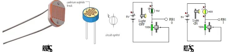
4. Light detector (Photoresistor).A photo-resistor(Figure 4.a) is used to detect the presence or absence of light in a room. A power supply of 5v DC obtained from USB connector is provided for this detector. The light detector is created using a photo-resistor (LDR) and a potentiometer of 100kΩ. The potentiometer is connected in serial using two Pot terminals. The Pot is used to control the light sensibility. Node between Pot and LDR must be connected to digital port RB1. Figure 4.b shows the diagram of how to do the connection.
a)
b)
Figure 4. a) Light resistor (LDR). b) Diagram of the light detector with a photo resistor (LDR)
a) b) c)
Figure 5. a) Parallax’s passive infra-red sensor. b) Diagram of the movement detector. c) Application of the movement sensor with indicator.
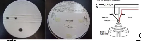
6. Smoke detector. This detector (Figure 6.a) works along an alarm which is activated when it detects smoke. It requires an external power supply connected to 120v AC. This detector has an internal alarm which is activated when it detects smoke. A relay and a transformer to convert 120v AC voltage to 5v DC is needed to connect the output of this detector as the input to the digital port RB3. Figure 6.b shows the connection of the smoke detector.
a)
b)
Figure 6. a) Kidde’s ionization smoke alarm. b)Diagram of the smoke detector.
IV.SOFTWAREIMPLEMENTATION
The following software were used to implement the program for the microcontroller and the PC client interface program:MikroC, mikroElektronika C compiler, PICkit 2 development programmer/debugger, EasyHID USB wizard, USBTrace (USB protocol analyzer), Microsoft Visual Studio 6.0, Microsoft Visual Studio 2008, SQL Server Management Studio Express 2005, and CadSoft Computer’s EAGLE Program (PBC layout and fabrication tool).
A. PROGRAMMING THE MICROCONTROLLER
1. Initial configuration. MikroC compiler was used to implementthe program for the PIC microcontroller. Device PIC18F5450 must be selected to create a new project. CPU speed of 48MHz was chosen for USB 2.0 interface. The following options of the wizard were used for the implementation: PLLDIV_2_1L, CPUDIV_OSC1_PLL2_1L, USBDIV_2_1L, FOSC_HSPLL_HS_1H, FCMEM_OFF_1H, IESO_OFF_1H, PWRT_ON_2L, BOR_ON_2L, BORV_43_2L, VREGEN_ON_2L, WDT_OFF_2H, WDTPS_256_2H, MCLRE_ON_3H, LPT1OSC_OFF_3H, PBADEN_OFF_3H, CCP2MX_ON_3H, STVREN_ON_4L, LVP_OFF_4L, ICPRT_OFF_4L, XINST_OFF_4L, DEBUG_OFF_4L.
The configuration PLLDIV_ is a pre-scaler function to divide the clock oscillator of the microcontroller by any assigned quantity. For this project a crystal quarz of 8MHz was used. The pre-scaler needs to be of 4MHz, for this reason PLLDIV_2_1L was selected to divide the clock speed by 2 producing 4MHz. 96MHz was obtained because the multiplexer (MUX) creates 4:96MHz PLL. This speed is divided by 2 producing 48MHz which is the required frequency to work with the high speed USB 2.0. More details about the internal clock of the microcontroller can be found on the page 24 of PIC’s reference manual [PIC].
The PORT A was programmed for analog inputs. The instruction TRISA = 0xFF starts PORT A as inputs. Channels
AN0, AN1, AN2,…,andAN12 are assigned for the analog inputs because they need to be converted internally in the microcontroller from analog to digital (A/D). Channel AN0was assigned to port RA0, channelAN1 to portRA1and channelAN2 toport RA2. PortsRA0 and RA1 are connected to temperature and humidity sensors respectively. The port
RA2 is connected to atmospheric pressure sensor. The temperature sensor is calibrated to measure in degree Celsius (°C), the humidity sensor in percent (%), and the pressure sensor in kilo-Pascals (kPa). The A/D converter works with 10 bits (210 = 1024).The output voltage of the A/D is multiplied by the reference voltage of USB (+5v) and then it is divided by 1024. All the voltages must in mili-voltios (mv) units. The initial step to convert the voltage of a sensor is given by the formula:
Conversion Volt. A/D = (Vsensor* 5000 mV) / 1024
Following the calibration specifications, the conversion of the temperature and humidity sensor is multiplied by 100 obtaining a temperature in °C and a humidity in %. The conversion of the pressure sensor is obtained in kPa. To convert kPa to mili-Bars (mB) we use the following formula: mB = (2.0*Vconversion + 0.95) / 0.009. Details of the A/D converter, the localization of the channel and the name of the instructions appear in the PIC18F4550 datasheet, pages 259 – 265 of the PIC’s reference manual [PIC].
The PORT B is programmed half to be digital inputs (RB0, RB1, RB2, RB3) and the other half digital outputs (RB4, RB5, RB6, RB7). The instruction ADCON1 = 0xFF initializes the PORT B to be used as input and/or output. The instruction TRISB = 0x0F (0000 1111) initializes half of the PORTB as input and the other half as output. More details about PORT A and PORT B,can be found in the PIC18F4550 datasheet, pages 111 – 116 of the PIC’s reference manual[PIC].
In the program, all the data of output ports (PORT A y PORT B) are assigned to specific arrays: Write_buffer[4], Temperature[8], Humidity[8], Pressure[8]. All these arrays are concatenated in a Buffer of 32 characters (bytes) declared asCat_Temp_Hum_Press_Digital[32]. The arrays: op[12], op2[12], op3[12], op4[12], are used to save data in string format.
Because buffers are used in excess, the program accumulates some blank spaces that result in garbage. The op arrays are used to remove the blank spaces. All the buffers are saved in the concatenate array calledCat_Temp_Hum_Press_Digital.
The instruction Hid_Write(&Cat_Temp_Hum_Press_Digital,32)was used to send all the 32 bytes of the buffer to the PC through USB interface. The instruction Delay_ms( ) assigns a delay in mili-seconds (ms) to the program.
B. COMPILATION
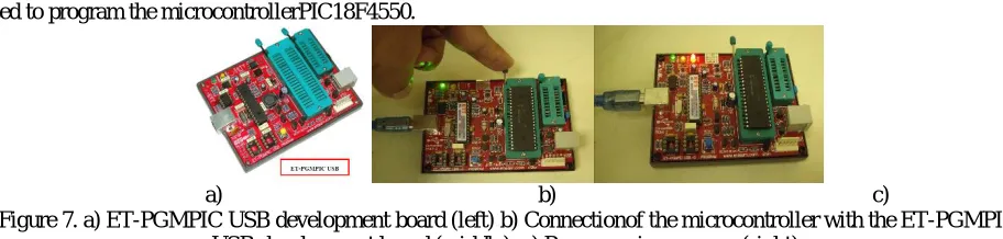
PICkit2 development programmer/debugger [Microchip] and development board ET-PGMPIC USB (Figure 7.a) were used to program the microcontrollerPIC18F4550.
a) b) c)
Figure 7. a) ET-PGMPIC USB development board (left) b) Connectionof the microcontroller with the ET-PGMPIC USB development board (middle). c) Programming process (right).
C. PROGRAMMING THE PC CLIENT INTERFACE
EasyHID [EasyHID] USB Wizard developed by Mecanique was used to develop a project in Visual Basic 6.0to work with the interface USB 2.0. In the first window of the wizard, the optionsCompany Name, Product Name and Serial Numberare optional. In the next window the options Vendor IDandProduct IDused areVID = 4660 and PID = 1. The VID y PID are authentic numbers assigned by the USB implementers (USB Implementers Forum, Inc.) and has a cost (www.usb.org). In the next window the options are: Polling (Input)- data required by the computer of the USB device (default: 10 ms);Polling (Output) - data that the computer sends to the USB device(default: 10 ms);Bus Power- maximum power consumed by the USB device (default: 50 x 2 mA = 100mA);Buffer (Input) - buffers that are sent from the USB device to the computer, maximum of 64 bytes (32 bytes were used), Buffer (Output): buffers that outs from the computer to the USB device, maximum of 64 bytes (32 bytes were used). In the next windows the following options were chosen:Project Name (optional),Location (hard drive), Compiler (microEngineeringLabs PICBASIC PROTM), Microcontroller (18F5450), and Application Compiler (Microsoft Visual Basic 5.0). The project created using EasyHID includes a module called HIDDLLInterface (mcHIDInterface.bas), Visual Basic uses this code to manage instructions of the USB interface. Figure 8 shows the main methods and files used to implement the client interface program. In addition, the created project includes a MainForm (FormMain.frm) to include objects to interact with the USB device.
Figure 8. Client interface program description
Figure 9. PC client interface program to monitor physical variables in a room.
An additional form as part of the client interface program was implemented to send the received data from the acquisition device to the database server. This program can control different devices through the internet using the database. In this way the system can detect the temperature, humidity, light on/off and movement in different rooms. This program has the capability to send messages to the server to execute some events, such as to turn on or off a light bulb. The figure 9 shows the implemented client interface program.
D. DATABASE IMPLEMENTATION
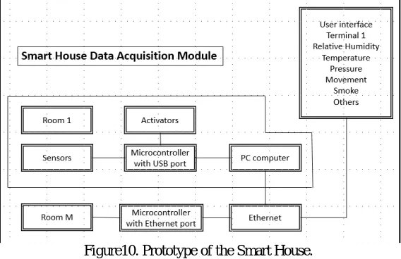
The structure of the database was developed using SQL server.Each table of the database was created to store data for each monitored sensor: temperature, pressure, humidity, smoke detector, movement detector, state of the door’s switch, and the state of the presence or absence of light. We used Microsoft SQL Server and SQL Management Studio Express to create this database. Figure 10 shows the diagram how the database is integrated in the prototype system.
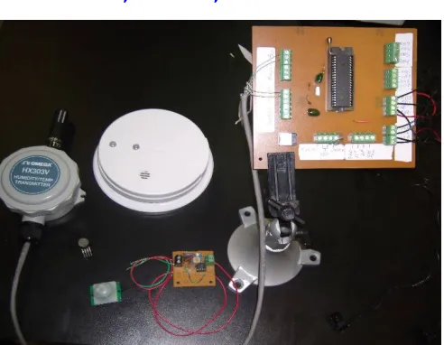
Figure10. Prototype of the Smart House.
respective table and an instance is created in the report table for each hour (hourly report). When the report button is pressed a new windows appears to display the stored data in a specified hour. When the windows appears, the drop down list must be completed with the desired hour and date.
V. SIMULATION RESULTS
A. PROTOTYPE DATA ACQUISITION MODULE
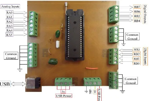
Figure 11 displays the outputs and inputs ports of the prototype circuit board of the data acquisition module. The analogue inputs are used to measure temperature, relative humidity and atmospheric pressure. Also, the prototype displays the digital outputs which are used to execute commands to active the radio, the light bulb, the air conditioner, and any electro-domestic device. Digital inputs are used to measure the presence of movement, smoke, light and the state of a door. Also, in this figure appears the microcontroller PIC 18F4550 and the USB ports.
Figure 11. Prototype circuit board of the data acquisition module
B. DESCRIPTION OF THE SYSTEM.
The proposed system gives intelligence to a house by adding sensors and activators to a microcontroller. The sensed data read by the circuit boards are collected by the PIC 18F4550 microcontroller to send these data to the client computer through the USB port. The client program sends these data to sever through the Ethernet port. These sensors can measure analogue variables such as temperature, humidity, and pressure and digital variables such as the activation of door’s sensors, light, movement and smoke detector.This data acquisition module is capable of turning on or off an alarm, a radio, a light bulb or an air conditioner. For this purpose, the client program sends a command to the microcontroller through the USB port. The microcontroller uses the port B as an output port. The port B is parallel port with 8 bits. Four of these are for output and the other four are for input. A client program implemented in Visual Basic manage the information in the personal computer. A program implemented using the C language manages the information in the microcontroller.
VI.FINDINGSANDCONCLUSIONS
A. RESULTS
Figure 12. Final design of the prototype circuit board
Figure 12 shows the final design of the circuit board inside the boxconnected to the input commands circuit board. This board allows to the user to control digital outputs locally in addition to the client computer. For instance, the client interface program controls the light bulb to turn on or off remotely. But a local control is needed to allow the user to turn on or off the light bulb. This command circuit board has four exclusive OR gates capable to execute the necessary logic to turn on or off the light bulb locally. The system has four logic local controls. The smoke and movement sensors (Figure 6.a) are mounted in the top of the room because they work better in that place. The temperature and humidity sensors are two sensors in one. In one side the temperature is read and in the other side the relative humidity is read. The light bulb is driven by a solid state relay to control the necessary voltage to the bulb. Only one solid state relay is able to manage twelve light bulbs. In this prototype a relay was used to manage the light bulbs, turning on or off the radio, air conditioning and alarms. The switches are used to detect if the door is open or not. Also, it is used to activate the logic commands coming from the logic OR circuit. The light sensor is used to detect if the light bulb is turning on or off, it is the reason why it was used in digital mode. All of these sensor and circuits appears in the Figure 12. The house acquires more intelligence when more sensors are added to it. Many experiments was made to proof the operation of the prototype system. Finally sensor’s voltage adjustment to convert the raw data in standard units for the user was performed.
B. CONCLUSIONS.
A complete software and hardware system was developed to monitor physical environment variables and actuators. This system is composed of a data acquisition module connected to a client PC. This prototype system was implemented in C, Visual Basic, and SQL. This system can be used for advance technologies like intelligent buildings, security monitoring, natural disaster prediction and handling. It can be accomplished with only a few software libraries and a small sensor board. This system can be enhanced to handle a large number of monitoring system devices without need of complicated software modifications.The software developed could provide to the scientific community an open tool to create complex and advanced ideas with an outstanding layer of abstraction.
C. FUTURE WORK
ACKNOWLEDGMENTS
This project was sponsored by the University of Puerto Rico at Bayamón, NASA, and the Alliance for Minority Participation,and NFS Grant CNS-0837556. We also thanks to students from Electronics Department for collaborating in this project: José R. De León Cacho, and Christian A. Arroyo Ovalles, Jesús M. Rodríguez Carriles and the student Marcel Rivera Ayuso from Computer Science Department. This document was edited by Prof. Antonio Huertas from Computer Science Departament of University of Puerto Rico. Special thanks to Florian Leitner Fisher for provide us the HID library.
REFERENCES
1. X. Zhenghua, C. Guolong, H. Li, Q. Song, L. Hu, C. Lei, M. Youwen, X. Yexiang,The Smart Home System Based on the Iap15f2k61s2 and
Gsm. International Journal On Smart Sensing And Intelligent Systems, Vol. 7, No. 4, pp. 1789-1806, 2014.
2. F. Shawki, M. E. .Dessouki, A. I. Elbasiouny, A. N. Almazroui, F. M. R. Albeladi, Microcontroller Based Smart Home With Security Using
Gsm Technology, International Journal of Research in Engineering and Technology, Vol. 04 No 06, pp. 20-28, 2015.
3. O. Edward, O. Olabode,A Microcontroller Based Building Automation System for real time Sensing and Control. International Journal of
Innovation and Scientific Research. Vol. 2 No. 2. pp. 275-280, 2014.
4. Ibrahim Dogan,Advanced PIC Microcontroller Projects in C: from USB to RTOS with the PIC18F Series, Newnes Publications,2008.
5. Z. Abdulzahra, R. S. Kawitkar,Implementation of Smart Home Control by Using Low Cost Arduino & Android Design, International Journal of
Advanced Research in Computer and Communication Engineering, Vol. 5, No 2. pp. 248-256, 2016.
6. I. Kaur,Microcontroller Based Home Automation System with Security, International Journal of Advanced Computer Science and
Applications,Vol. 1, No. 6, pp. 60-65, 2010.
7. B. Bhaskar, R. Swarnalatha,Smart Home Automation System Using AVR Microcontroller, International Journal of Advanced Technology in
Engineering and Science, Vol 3, No. 02, pp. 234-242, 2015.
8. R. Panna, R. Thesrumluk, C. Chantrapornchai, Development of Energy Saving Smart Home Prototype, International Journal of Smart Home,
Vol. 7, No. 1. pp. 47-66, 2013.
9. Microchip Technology Inc,PIC18F2455/2550/4455/4550 Data Sheet, 28/40/44-Pin, High Performance, Enhanced Flash, USB Microcontrollers
with nanoWatt Technology, 2007.
10. MikroC, MicroC Compiler, Available:http://www.mikroe.com/,[Accesed : 10 – Oct. 2016].
11. Mecanique, Easy HID,Available:http://www.mecanique.co.uk/products/usb/easyhid.html, [Accesed : 10 – Oct. 2016].
12. Floyd, Thomas L,Digital Fundamentals with VHDL. Pearson Education, Inc. Prentice Hall Publications, 2003.
BIOGRAPHY
M. S. Ismael Sanchez Rios received B.S. in Electrical Engineering at University of University of Puerto Rico at Mayaguez Campus in 1986.He received M. S. in Electrical Engineering at Purdue University in 1992. M.S.Sanchez is with the department of Electronic, University of Puerto Rico at Bayamón, San Juan, PR, 00959 USA. His research interest is in robotics, microcontrollers, and digital and analog electronics.
Dr. Elio Lozano received B.S. in mathematics at National University of San Antonio Abad of Cusco, Perú in 2000. He received M.S. in Scientific Computing and Ph.D. in Computer and Information Science and Engineering at University of University of Puerto Rico at Mayaguez Campus in 2003 and 2006 respectively. Dr. Lozano is with the department of Computer Science, University of Puerto Rico at Bayamón, San Juan, PR, 00959 USA. He has developed several software and firmware for different architectures.
PhD. Student Victor Santos Uceta received B.S. in Computer Science of the University of Puerto Rico at Bayamón. He is currently pursuing a Ph.D. degree in Computer Science at Purdue University with focus on Distributed Systems, Software Engineering, and applications of machine learning in interdisciplinary fields.