EVALUATION OF CRACK ARREST LENGTH AND CRACK ARREST
TOUGHNESS OF COLD-WORKED AND AGED MODIFIED 9CR-1MO
STEEL BY APPLICATION OF KEY-CURVE METHOD
S.Sathyanarayanan, A.Moitra, G.Sasikala, A.K. Bhaduri and V.Singh*
Materials Technology Division
Indira Gandhi Centre of Atomic Research Kalpakkam, India -603102
*Department of Metallurgical Engineering
Institute of Technology, Banaras Hindu University Varanasi, India 521005
E-mail of corresponding author: [email protected]
ABSTRACT
Crack Arrest Toughness (KIA) is being proposed as a characteristic material toughness below which cleavage fracture does not occur. KIA is usually obtained by means of large specimens like the Compact Crack Arrest (CCA) specimens used in ASTM standard E1221. Obtaining KIA from small size Charpy specimens would be of utility to the nuclear industry because of their usage as nuclear surveillance specimens. Literature reports indirect methods of obtaining KIA from Charpy specimens by empirical correlation with results obtained from larger specimens. In a recent study, the authors have proposed a method for direct evaluation of KIA from instrumented impact tests of pre-cracked Charpy specimens and applied it to modified 9Cr-1Mo steel. In the present study, this method is extended to the same steel in thermally aged condition.
The load-displacement traces obtained from instrumented Charpy-V impact tests with fatigue pre-cracked specimens of a modified 9Cr-1Mo steel in 0%, 10% and 15% cold worked and aged (650 °C/10000h) condition in the transition temperature regime bear signatures of crack arrest, because after crack initiation the load does not fall to zero level as observed for total cleavage fracture. While the arrest load can be determined from the load-displacement traces, assessment of crack length at arrest is an uncharted domain. This is mainly because no unequivocal signature of arrest can be found on the fracture surface enabling direct measurement. In this study, the
Key-Curve technique has been effectively used to assess the crack arrest length that is subsequently used for
estimation of the crack arrest toughness (KIA).
The Key-Curve commonly used for ductile fracture, expresses the load (P) as a separable and multiplicative function of ligament length (b) and displacement (d) in the form P = B*W*(b/W)η*H(d/W), where B and W are
standard specimen dimensions and η = 2 for 3PB specimens and H is a power law function. In this study, this has been applied for cleavage fracture. The constants in the Key-Curve expression were obtained by fitting the load– displacement pairs between yield point and peak load preceding cleavage fracture and used to obtain crack arrest length. The results were validated by comparing with final crack length measured optically on unbroken specimens of 15% cold worked material aged for 650°C/5000h.
Using the arrest load and the arrest length, KIA has been determined using the ASTM E399 expression. The average KIA for 0, 10 and 15% cold-worked and aged (650°C and 10000 h) datasetsare 62.7, 65.8 and 69.9 MPa.m0.5 respectively. The datasets indicate substantial scatter in crack initiation phenomenon contrary to the arrest. The scatter in crack initiation toughness was characterized by the three parameter Weibull distribution used in the reference temperature based Master Curve approach. The corresponding median KJd, where KJd is the dynamic crack initiation toughness, for the three datasets are 74.3, 72.2 and 81.2 MPa.m0.5 respectively.
Keywords: Crack arrest, key curve, cleavage fracture, DBTT, ferritic steel.
1. INTRODUCTION
specimens. Sokolov et al. [4] have statistically analysed the crack arrest load by a two parameter Weibull plot, and the load at a cumulative arrest probability of 0.632 has been empirically correlated with nil ductility transition temperature TNDT. In other efforts [5–9], the temperature of occurrence of specific arrest load levels such as 3 or 4 kN etc. as determined from instrumented Charpy tests have been correlated with TNDT and also to TKIA (temperature corresponding to median arrest toughness=100 MPa·m0.5), enabling the determination of KIA from the empirical curves. It may be observed that in the above efforts, KIA has been obtained by indirect means through empirical correlations. Obtaining KIA directly from instrumented impact tests of Charpy specimens would further improve the utility of these tests.
The evaluation of KIA requires the determination of crack arrest load Parrest and crack arrest length aarrest. The value of Parrest can be obtained directly from the load-displacement plot. The uncertainty in the determination of
aarrest in a Charpy impact test can stem from the following facts: First, the crack continues to extend beyond aarrest during the course of the test, and second, there is no unequivocal microstructural feature to identify the aarrest in Mod. 9Cr-1Mo steel. Further, till date no standard test methodologies are available to determine the crack arrest length from these tests. Hence, an analytical technique, namely, the ‘key curve’ method has been recently employed by the authors to obtain aarrest and hence, KIA for Mod. 9Cr-1Mo steel in the normalized and tempered condition [10].This method has been extended to the cold worked and aged Mod.9Cr-1Mo steel.
The basis of the key curve method is the expression of load P as a multiplicative and separable function of crack length a or ligament length b and plastic displacement dpl [11]. This method has been successfully used to describe the fracture behaviour of ductile metals for both stationary [12] and growing cracks [13]. It is also used in ASTM E 1820-09 e1 to estimate current crack length for ductile fracture conditions. Under ductile fracture and dynamic loading conditions, this method has proven successful in calculating current crack length for low velocity impact tests of AISI 316SS pre-cracked Charpy specimens [14]. In ductile fracture, the use of total displacement d instead of plastic displacement dpl has found preference and been proven successful [15,16] when the yield point is not well defined, such as in aluminum alloys. The functional forms and methodology used when total displacement is the variable are similar to those for the key curve using plastic displacement [12,13]. The key curve method has been applied successfully for estimating the pop-in crack extension [17] occurring during ductile fracture for C(T) specimens of Mod.9Cr-1Mo steel under quasistatic loading and fixed grip conditions. For the small pop-in crack extension as compared to the larger specimen dimensions, the change in plastic displacement (dpl) is negligible and can be assumed constant. A modification of this approach [10] has been adopted to evaluate aarrest for cleavage fracture and arrest of unaged Mod. 9Cr-1Mo steel occurring in the ductile-brittle transition temperature regime. In the present study, the same methodology has been applied for analyzing the crack arrest occurring in cold worked and aged Mod. 9Cr-1Mo steel.
2. MATERIAL
The material used in this study is a Mod.9Cr-1Mo steel in the normalized and tempered (N&T) condition, and subsequently cold worked levels of 10 % and 15%. The steel was supplied in N&T (1095 and 780°C/1h) condition with a tempered martensitic microstructure in the form of a 30 mm thick plate. The chemical composition (in wt %) is given in Table 1. Cold work, corresponding to reductions in cross sectional area by 10% and 15%, was imparted on round bars of 17.2 mm & 17.7 mm diameters and 500 mm length in a rotary swaging machine at ambient temperature. Further, the N&T and prior cold worked material were thermally aged at a temperature of 650 °C for 10000 hours.
Table 1: Chemical composition of Modified 9Cr-1Mo steel used in weight percentage
3. EXPERIMENTAL
A series of impact tests were conducted on full size (10*10*55 mm3) Charpy specimens, fatigue pre-cracked to an ao/W ≈ 0.5, using an ‘Accelerated Drop-Weight Testing’ machine. The tests for N&T , 10% and 15% prior cold worked material were conducted at temperatures of 80°C, 75°C and 75°C respectively. All the tests were
C Mn P S Si Cr Mo Ni Al Nb V N Fe
-0.5 0.0 0.5 1.0 1.5 2.0 2.5 3.0 3.5 4.0 4.5 5.0 0
1 2 3 4 5 6
Modified 9Cr-1Mo steel
Normalised & Tempered
Aged at 650oC,10000 Hours P
arrest
Cleavage Initiation
lo
a
d
,
k
N
specimen displacement, mm
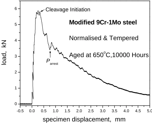
conducted at loading rates of 1.1 ± 0.1 m/s. The mass of the impacting hammer was 27.993 kg. The machine was instrumented enabling recording of the load-time data over the impact duration. The obtained load-time plots are converted to load–displacement plot. A typical load-displacement plot is shown in Fig. 1.
Fig 1: Load – Displacement plot of Normalised & Tempered Mod. 9Cr-1Mo steel aged at 650 °C and 10000 Hours
4. RESULTS AND DISCUSSION
With an aim to evaluate the crack arrest toughness (KIA), the crack arrest load (Parrest) and the crack arrest length (aarrest) have been determined using the load-displacement traces obtained from the instrumented impact test.
The determination of Parrest requires load-time or load-displacement plots. As can be seen from Fig.1, the load-displacement plots can be divided in three different regimes: 1) load systematically rises up to the maximum load followed by 2) sharp drop at the maximum point indicating cleavage crack propagation till the arrest point and 3) post arrest loading marked with initial oscillations followed by a declining trend in the average load level till the specimen is detached from the hammer. In the regime 1, the initial loading is linear indicating elastic deformation, followed by deviation from linearity indicating plasticity, which has been found to be of minimal extent in the present campaign. The load drop in regime 2, indicative of cleavage crack propagation, deviates from the conventional cleavage fracture scenario in the sense that the conventional cleavage is marked by sharp load drop up to the zero level where as in the present circumstances the load drop is arrested at a level much higher than zero, indicating crack arrest. This arrest point has been assigned as the crack arrest load (Parrest), as shown in Fig.1 and used for further calculations. The cleavage initiation load has been identified in regime 2 as the point from which the load shows a sudden fall, and crack initiation toughness (KJd) also has been evaluated with this load. In regime 3, the reason for occurrence of oscillations around a mean declining load level is a matter of speculation. In the earlier study with unaged 9Cr-1Mo steel [10], this aspect has been correlated to the discontinuous crack propagation in the microscopic level through the martensitic packets and prior austenitic grains, where the cleavage facet propagation was periodically resisted by high angle boundaries giving rise to substantial ductile band formation. The extent of plasticity has been more pronounced as the crack extends through the specimen. In regime 3, the curvature of the load displacement plot is symptomatic of ductile fracture.
extensions and corresponding load drops are much larger in the present case; (iii) there is limited plasticity before occurrence of cleavage fracture in the present study. Due to the first two reasons, dpl and d do not maintain constancy during cleavage fracture and arrest. Due to the limited plasticity, instead of using the key curve with plastic displacement dpl as the variable, the key curve using total displacement d as a variable has been applied in the present case.
The functional form of the key curve used in the present study is as given below:
P = B *W * (b/W) η * H (d/W) (1)
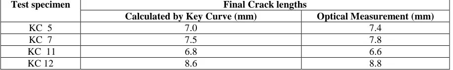
For deeply cracked TPB specimens, η =2. H (d/W) has been expressed as a power law. This method requires the unbroken final crack length for validation. For the material in the present study, all the specimens had fully fractured during the course of the tests. However, the same material in 15% cold worked condition and under thermal aging conditions of 650 °C \ 5000 hours had a few specimens which were not fully broken during the course of the tests. The material in the above cold worked and thermally aged condition displayed load-displacement plots identical to the material in this study. This justifies the use of the 15% cold worked material thermally aged at 650 °C \ 5000 hours to validate the key curve for the material in this study. The key curve using the functional form of Eqn. 1 was used to fit the P-d pairs after yield and before cleavage fracture. The fitted key curve was used to calculate the final crack length using the last P-d pair in the test record. As given in Table 2, the final crack lengths calculated using the key curve are in good agreement with the optically measured crack lengths. This confirms the validity of the application of the key curve fitted with inputs of P-d pairs before cleavage fracture, with the obtained fit being applied to P-d pairs after cleavage crack arrest. Similarly, P-d pairs before cleavage fracture were fitted to the key curve, and the obtained fit was used to obtain crack arrest lengths (aarrest) using the P-d pair at crack arrest.
Table 2: Comparison of unbroken final crack lengths calculated using Key curve method and by optical measurement for 15% cold worked Mod. 9Cr-1Mo steel aged at 650 °C and 5000 Hours
Using Parrest, aarrest, and the relevant specimen dimensions, KIA has been determined from standard linear elastic fracture mechanics stress intensity factor K equation as given in ASTM E399-90 e1 [18]. The equation for obtaining K1A is as follows:
KIA = {P*S/[ (B*BN)1/2*W3/2] }f(aarrest/W) (2)
where: P=load (Parrest in the present case), S=span, B=specimen thickness, BN=net section thickness (BN=B in the absence of side grooves), W=specimen width, and a=crack length (aarrest in the present case).
The KIA values thus determined using crack arrest lengths obtained by the key curve method for the cold worked and aged Mod.9Cr-1Mo steel are given in Tables 3a to 3c along with the Ttest (test temperature), aarrest and
Parrest values. KJd is the crack initiation toughness, and a0 is the initial crack length. The maximum and minimum KIA of each dataset varies from the mean value by +15.3% to −7.8% for Normalised & Tempered, +7.5% to −5.5% for 10% cold worked, and +4.5% to −9.7% for 15% cold worked material. This indicates that KIA is an average property and not statistical in nature. The mean KIA is 62.7, 65.8 and 69.9 MPa.m0.5 for Normalised & Tempered, 10% cold worked, 15% cold worked and aged material respectively. Considering the scatter inherent in toughness under dynamic loading conditions, the change in KIA with cold work can be considered to be insignificant. On the other hand, crack initiation toughness (KJd )indicates substantial scatter varying from 65.87 to 110.63 MPa.m0.5 for Normalised & Tempered, from 59.35 to 113.28 MPa.m0.5 for 10% cold worked, and from 69.01 to 114.66 MPa.m0.5 for 15% cold worked and aged material. The statistical scatter in KJd was characterized by the three parameter Weibull distribution used in the reference temperature based Master Curve approach. The corresponding median
KJd, where KJd is the dynamic crack initiation toughness, for the three datasets are 74.3, 72.2 and 81.2 MPa.m0.5 respectively.
In an impact test, there are inertial effects originating from the specimen-hammer interaction, giving rise to oscillations in the load-time trace, at least in the initial part of loading. This is considered as a major source of error in the load measurement under dynamic loading conditions. One of the experimental means [19, 20] to reduce this
Final Crack lengths Test specimen
Calculated by Key Curve (mm) Optical Measurement (mm)
KC 5 7.0 7.4
KC 7 7.5 7.8
KC 11 6.8 6.6
error has been to reduce the loading rate which gives rise to simultaneous reduction in the oscillation amplitude. However, reduction in loading rate costs the dynamic effect and thus the loading rate needs to be optimized to maintain a sufficient stress intensity factor rate to ensure a dynamic loading. This has been optimized by Moitra et
al. [21-24] at ~1.1m/s for plain 9Cr-1Mo and Mod.9Cr-1Mo steels and their welds. The amplitude of inertial
oscillations [25] is also considered negligible beyond a time span of ≈ 3, where is the time period of oscillations.
Also, loss of contact effects [26] is minimal when the energy criterion E0≥ 3ET is met. E0 is the initial pendulum energy and ET is the total energy absorbed by the specimen. By meeting the above criteria, dynamic fracture toughness K1d [27-29] has been estimated to have an accuracy of ± 20%. In the present study, tests have been conducted at a reduced impact velocity of 1.1 ± 0.1 m/s and the fracture loads have been found to conform with the 3 criterion. Thus the accuracy in the crack arrest toughness (KIA) can be inferred to be within ± 20%.
Table 3a: Test Temperature (Ttest), crack arrest load (Parrest), crack arrest length (aarrest), crack arrest toughness (KIA) and mean KIA for Normalised & Tempered Mod. 9Cr-1Mo steel aged at 650 °C for 10,000 Hours
Spec. No: Ttest ( °C)
Parrest
(kN)
aarrest
(mm)
KIA,
MPa. m0.5
Mean KIA,
MPa. m0.5
MD1 80 3.97 5.99 59.75
MD2 80 3.53 6.19 57.69
MD3 80 3.87 6.17 62.69
MD4 80 3.80 6.44 68.75
MD5 80 3.77 6.18 61.39
MD6 80 3.28 6.42 58.91
MD7 80 3.43 6.46 62.64
MD9 80 3.48 6.33 60.05
MD10 80 3.39 6.80 72.20
62.62
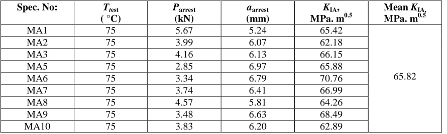
Table 3b: Test Temperature (Ttest), crack arrest load (Parrest), crack arrest length (aarrest), crack arrest toughness (KIA) and mean KIA for 10% cold worked Mod. 9Cr-1Mo steel aged at 650 °C for 10,000 Hours
Spec. No: Ttest ( °C)
Parrest
(kN)
aarrest
(mm)
KIA,
MPa. m0.5
Mean KIA,
MPa. m0.5
MA1 75 5.67 5.24 65.42
MA2 75 3.99 6.07 62.18
MA3 75 4.16 6.13 66.15
MA5 75 2.85 6.97 65.88
MA6 75 3.34 6.79 70.76
MA7 75 3.74 6.41 66.99
MA8 75 4.57 5.81 64.26
MA9 75 3.48 6.63 68.49
MA10 75 3.83 6.20 62.89
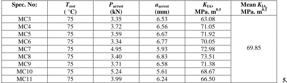
Table 3c: Test Temperature (Ttest), crack arrest load (Parrest), crack arrest length (aarrest), crack arrest toughness (KIA) and mean KIA for 15% cold worked Mod. 9Cr-1Mo steel aged at 650 °C for 10,000 Hours
5.
CONCLUSIONS
a) Crack arrest length (aarrest) has been determined for cold worked and aged Mod. 9Cr-1Mo steel using the ‘Key-Curve’ method. Also, crack arrest toughness (KIA) has been calculated for the cleavage fracture and arrest tests occurring in the ductile – brittle transition temperature regime.
b) The average KIA is 62.62, 65.82 and 69.85 MPa.m0.5 respectively for Normalised and Tempered, 10% cold worked and 15% cold worked Mod. 9Cr-1Mo steel aged at 650 °C for 10000 hours.
REFERENCES:
[1] Timofeev, B. T., Karzov, G. P., Blumin, A. A., and Smirnov, V. I., Int. J. Pressure Vessels Piping, Vol. 77, 2000, pp. 519–529.
[2] Bryan, R. H., Bass, B. R., and Merkle, J. G., Eng. Fract. Mech., Vol. 23(1), 1986, pp. 81–97.
[3] ASTM E1221-06, 2006, “Standard Test Method for Determining Plane-Strain Crack Arrest Fracture Toughness,
K1a, of Ferritic Steels,” Annual Book of ASTM Standards, ASTM International, West Conshohocken, PA.
[4] Sokolov, M. A., and Merkle, J. G., Pendulum Impact Testing: A Century of Progress, ASTM STP 1380, T. A. Siewert and M. P. Manahan, Eds., ASTM International, West Conshohocken, PA, 2000, pp. 382–393.
[5] Planman, T.,Wallin, K., and Rintamaa, R., 14th International Conference on Structural Mechanics in Reactor Technology (SmiRT 14), Lyon, France, Aug. 17–22, 1997, International Association for Structural Mechanics in Reactor Technology, Berlin, Germany, pp. 415–422.
[6] Wallin, K., Report No. VTT-MET B 221, Metals Laboratory, Technical Research Centre of Finland, Espoo, Finland, January 1993.
[7] Ahlf, J., Bellmann, D., Fohl, J., Hebenbrock, H., Schmitt, F. J., and Spalthoff,W Radiation Embrittlement of Nuclear Reactor Pressure Vessel Steels: An International Review (Second Volume), ASTM STP 909, L. E. Steels, Ed., ASTM International, West Conshohocken, PA, 1986, pp. 34–51.
[8] Fabry, A., Small Specimen Test Techniques, ASTM STP 1329, W. R. Corwin, S. T. Rosinski, and E. Van Walle, Eds. ASTM International, West Conshohocken, PA, 1998, pp. 274–297.
[9] S. K. Iskander, R. K. Nanstad, M. A. Sokolov, D. E. Mccabe, J. T. Hutton, and D. L. Thomas, Effects of Radiation on Materials: 18th International Symposium, ASTM STP 1325, R. K. Nanstad, M. L. Hamilton, F. A. Garner, and A. S. Kumar, Eds., ASTM International, West Conshohocken, PA, 1999, pp. 204–222.
[10] S. Sathyanarayanan, A. Moitra, G. Sasikala, A. Dasgupta, S. Saroja, A. K. Bhaduri, Baldev Raj, and Vakil Singh, To be published in Journal of Testing and Evaluation, Vol. 39, No: 3, May 2011.
[11] Ernst, H. A., Paris, P. C., and Landes, J. D., Fracture Mechanics : 13th Conference, ASTM STP 743, R. Roberts, Ed., ASTM International,West Conshohocken, PA, 1981, pp. 476–502.
[12] Sharobeam, M. H. and Landes, J. D., Int. J. Fract., Vol. 47, 1991, pp. 81–104. [13] Sharobeam, M. H. and Landes, J. D., Int. J. Fract., Vol. 59, 1993, pp. 213–226.
Spec. No: Ttest ( °C)
Parrest
(kN)
aarrest
(mm)
KIA,
MPa. m0.5
Mean KIA,
MPa. m0.5
MC3 75 3.35 6.53 63.08
MC4 75 3.72 6.56 71.05
MC5 75 3.59 6.67 71.92
MC6 75 3.34 6.77 70.05
MC7 75 4.95 5.93 72.98
MC8 75 3.40 6.83 73.51
MC9 75 3.71 6.58 71.38
MC10 75 5.24 5.61 68.67
MC11 75 3.99 6.24 66.50
[14] Sreenivasan, P. R. and Mannan, S. L., Int. J. Fract., Vol. 101, 1999, pp. 229–249.
[15] Cassanelli, A. N., Ortiz, H., Wainstein, J. E., and deVedia, L. A., Fatigue and Fracture Mechanics: 32nd Volume, ASTM STP 1406, R. Chona, Ed.,ASTM International,West Conshohocken, PA, 2001, pp. 49–72.
[16] Cassanelli, A. N., Cocco, R., and de Vedia, L. A., Eng. Fract. Mech., Vol. 70, 2003, pp. 1131–1142. [17] Sasikala, G. and Ray, S. K., Mater. Sci. Eng., A, Vol. 479, 2008, pp. 105–111.
[18] ASTM E399-90 e1, 2009, “Standard Test Method for Linear- Elastic Plane-Strain Fracture Toughness KIc of Metallic Materials,” Annual Book of ASTM Standards, ASTM International, West Conshohocken, PA. [19] Ireland, D. R., Instrumented Impact Testing, ASTM STP 563, ASTM International, West Conshohocken, PA, 1974, pp. 3–29.
[20] Ireland, D. R., “Critical Review of Instrumented Impact testing,” Dynamic Fracture Toughness, The Welding Institute, Cambridge, U.K., 1976, pp. 47–62.
[21] Moitra A., Sreenivasan P. R., Mannan S.L., Singh V., Metall. Mater. Trans. A 36A (2005) 2957.
[22] Moitra A., Ductile Brittle Transition Temperatures and Dynamic Fracture Toughness of 9Cr–1Mo steel, Ph.D. Thesis, Banaras Hindu University, India, 2003.
[23] Moitra, A., Sathyanarayanan, S., Albert, S. K., Ramasubbu, V., Sasikala, G., Samuel, K. G., and Ray, S. K., Int. J. Pressure Vessels Piping, Vol. 85, 2008, pp. 478–485.
[24] Sathyanarayanan S. , Moitra A. ,Samuel K.G. , Sasikala G. , Ray S.K.,Singh V., Materials Science and Engineering A 488 (2008) 519–528.
[25] Ireland, D. R., “Discussion Session II: Elastic Fracture: Initiation 2,” Proc. Int. Conf. On Dynamic Fracture Toughness, London, United Kingdom, July 1976, The Welding Institute, Cambridge, U.K., 1997, pp. 360–372. [26] Kobayashi, T., Yamamoto, I., and Niinomi, M., Eng. Fract. Mech. Vol. 26(1), 1987, pp. 83–94.
[27] Turner, C. E., Advanced Seminar on Fracture Mechanics, EURATOM-ISPRA Courses, _, 1975.
[28] Burdekin, F. M., Practical Fracture Mechanics for Structural Steel, Proc. Symp. on Fracture Toughness Concepts for Weldable Structural Steel, Risley, United Kingdom, April 1969, M. O. Dobson, Ed., UKAEA and Chapman and Hall, Risley, 1969, p. C1.