20th International Conference on Structural Mechanics in Reactor Technology (SMiRT 20) Espoo, Finland, August 9-14, 2009 SMiRT 20 - Division V, Paper 1594
Earthquake-Induced Sloshing Effects
on Seismic Qualification of Liquid Storage Tanks
Xian-Xing (Lambert) Li
aa
SNC-Lavalin Nuclear Inc., e-mail: [email protected]
Keywords: Tank, Sloshing, Earthquake, Response Spectrum, Modal Analysis.
1
ABSTRACT
A practical approach, based on the concept of equivalent tank, is presented for seismic qualification analysis of rigid supported liquid storage tanks of general shape. The classical code equations available for simple tanks are extended to general tanks with reasonable accuracy.
Assuming ideal liquid conditions and small-amplitude elevation of the free surface, the liquid motion in an undeformed tank of general shape can be approximated by the corresponding motion of an equivalent vertical cylindrical or rectangular tank. The modal properties of the liquid including frequencies, mode shapes, modal masses, and heights of modal mass centres can be obtained through the tank equivalence. Based on an impulsive-convective decomposition, the seismic response in terms of dynamic pressure, base shear and over-turning moment of the tank can be evaluated.
The proposed approach can be applied to general industrial tanks including vertical cylindrical, horizontal cylindrical, rectangular, spherical and other tanks. The established equations are readily applicable in the frame work of practical seismic qualification of liquid storage tanks.
2
INTRODUCTION
There has been an upsurge of interest in developmental activities aimed at producing better seismic design methods for liquid storage tanks due to stringent requirements on the safety of liquid storage tanks in nuclear power plants. Sloshing response under seismic events is of particular importance for a reliable estimate of the base shear, the overturning moment, and the hydrodynamic pressure. Nevertheless, the applicable seismic codes for tanks of general shape are quite limited and not well developed as compared with the large number of codes applicable to vertical-cylindrical and rectangular tanks.
Classical solutions are available for rectangular and vertical-cylindrical tanks. For heavy storage tanks in a nuclear power generation plant, horizontal-cylindrical tanks, spherical tanks, and other types of tanks are frequently used. Exact analytical solutions for these types of tanks are unavailable, except for some special cases such as half-full of liquid. Approximate solution can be developed as an alternative toward a successful evaluation of sloshing effects.
International Building Code (IBC, 2006) provides seismic provisions for certain types of liquid storage tanks. However, this code is limited to liquid storage tanks with flat bottoms (rectangular or vertical-cylindrical tanks).
American Petroleum Institute (API, 1998) has two standards: API 650 and API 620, which provides provisions for design and construction of steel tanks. These standards refer exclusively to vertical-cylindrical tanks.
tanks with circumferential tendons. All these AWWA standards are only applicable to vertical-cylindrical tanks.
Eurocode 8, Part 4 (Eurocode 8, 2006) covers provisions for seismic design of tanks of cylindrical and rectangular shapes. This code includes some simple yet incomplete provisions for calculations of impulsive and convective masses of horizontal-cylindrical tanks. The procedure for the evaluation of sloshing is that the horizontal-cylindrical tank is equivalently replaced by a rectangular tank with the same length at the liquid level, the same dimension as the actual one in the direction of the seismic action and third dimension (depth) such that the liquid volume is maintained.
An important point to note is that the shape of a horizontal-cylindrical, spherical, and other general tanks do not fit into any standard coordinate system; therefore, it is difficult to develop an exact analytical methodology to evaluate the sloshing behavior. Although the velocity potential functions for sloshing in the rectangular and vertical-cylindrical tanks have been derived explicitly by the separation of variables, current sloshing theory has not yet developed an explicit velocity potential function for sloshing in horizontal-cylindrical, spherical and other tanks. Approximate yet practical solutions should be proposed for the seismic design of those types of tanks.
3
EQUIVALENT RECTANGULAR TANK
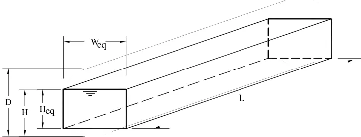
The solution with the idea of “Equivalent Rectangular Tank” adopted in Eurocode 8 (2000), Part 4, is used to analyze sloshing characteristics of liquid storage tanks with undisturbed free surface of liquid close to the rectangular shape. An example for this application can be given to the horizontal cylindrical circular tank with flat ends, in which the free surface is exactly in rectangular shape. Fig. 1 shows the concept of the equivalence of horizontal cylindrical tank to a rectangular tank.
Heq
L
Weq
H D
Fig. 1 Concept of equivalent rectangular tank
This approximation is applicable to H/D!0.8. For H/D>0.8, the tank is considered to behave as if it were full without sloshing effects. The dimension of the equivalent rectangular tank, as shown in Fig. 1, is determined as follows:
• Horizontal longitudinal dimension,Leq, is equal to the longitudinal length of the undisturbed free surface.
• Horizontal transverse dimension, Weq, is equal to the width of the undisturbed free surface. • Liquid height, Heq, in the equivalent rectangular tank is determined such that the liquid
volume is maintained. 3.1 Dynamic characteristics of sloshing
3.1.1 Modal frequencies
According to sloshing solutions for rectangular tanks, the following closed-form expressions can be used to calculate the modal frequencies of longitudinal sloshing:
! ! " # $ $ % & ' ' = eq B eq H j eq B g j cj ( (
) (2 1) tanh (2 1) ; j=1,2,3,L (1)
3.1.2 Modal masses
The corresponding modal convective mass ratios are
! ! " # $ $ % & ' ' = eq B eq H j j eq H eq B T m cj m ( ( ) 1 2 ( tanh 3 ) 1 2 ( 3 8
; j=1,2,3,L (2)
3.1.3 Base shears
The convective base shear is given by
(
)
! " = = 1 2 j cj A cj m cQ (3)
The impulsive base shear is determined via
i A j cj m T m i Q ! ! " # $ $ % & ' ( = ) = 1 (4)
The total hydrodynamic pressure force is then 2 2 i Q c Q
Q= + (5)
3.1.4 Overturning moment
The convective overturning moment is
(
)
! " = = 1 2 j cj h cj A cj m cM (6)
where the height of centroid of convective mass, hcj, is given by
(
)
(
)
(
)
! ! ! ! ! ! " # $ $ $ $ $ $ % & ' ' ( ) * * + , -' ' ( ) * * + , -+ = eq B eq H j eq B eq H j eq B eq H j eq H H cj h . . . 1 2 sinh 1 2 1 2 cosh 2; j=1,2,3,L (7)
The hcj should be limited to
! ! " # $ $ % & ' T m cj m H D
2 due to tank top restriction. The impulsive overturning moment is
i h i A j cj m T m i M ! ! " # $ $ % & ' ( = ) = 1 (8)
where the height of centroid of impulsive mass, hi, is given by
(
2 /)
226 . 0 45 . 0 eq B eq H eq H eq H i
The height hi should also be limited to ! ! " # $ $ % & '' ( ) ** + , -T m c m H
D 1 1
2 due to the tank top restriction. The total hydrodynamic pressure overturning moment is then determined by
2 2 i M c M
M = + (10)
3.1.5 Hydrodynamic pressure on tank wall
The total pressure is given by the sum of an impulsive and a convective contribution: )
( ) ( )
(z pi z pc z
p = + (11)
The impulsive component of pressure is given by the expression:
(
)
(
)
(
)
22 5 . 1 / 2 2 / 1 . 0 / 1 2 ) ( eq eq eq B H i eq i B H B H H z A B z p + ! ! ! " # $ $ $ % & ! " # $ % & '
= ( + (12)
The convective pressure component is given by a summation of modal terms:
! " = # # $ % & & ' ( # $ % & ' ( ) # # $ % & & ' ( = 1 2 cosh 1 2 2 cosh ) ( j eq B H j j eq B z j cj A eq B z c p * * *
+ (13)
3.2 Frequency of horizontal cylindrical circular tank
Assuming the radius of the cylindrical base is R=D/2, the width and height of the corresponding equivalent rectangular tank is
2 2 2 ! " # $ % & ' = R H R H R eq
W (14)
! " # $ % & ' ( ) * + , -+ ' ( ) * + ,
-= cos 1 1
2 1 2 R H eq W R R H R eq
H . (15)
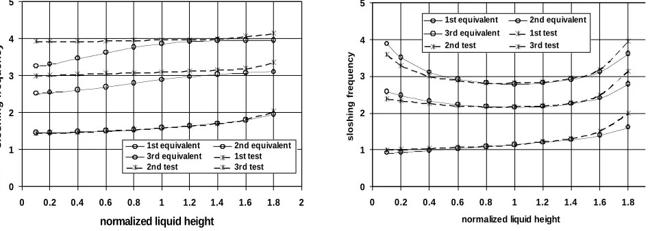
The natural frequencies of the tank can be calculated using Eq. (1). Fig. 2 shows the nondimensional natural frequencies for the first lowest longitudinal and transverse slosh modes, respectively, in which experimental results (Dodge, 2000) are used for comparison. It can be seen that the approximate results correspond well with the experimental values. Longitudinal Sloshing Frequency
0 1 2 3 4 5
0 0.2 0.4 0.6 0.8 1 1.2 1.4 1.6 1.8 2
normalized liquid height
s lo s h in g f re q u e n c y
1st equivalent 2nd equivalent 3rd equivalent 1st test 2nd test 3rd test
(a) Longitudinal slosh modes
Transverse Sloshing Frequency
0 1 2 3 4 5
0 0.2 0.4 0.6 0.8 1 1.2 1.4 1.6 1.8 2 normalized liquid height
s lo s h in g f re q u e n c y
1st equivalent 2nd equivalent 3rd equivalent 1st test 2nd test 3rd test
4
EQUIVALENT VETICAL CYLINDRICAL TANK
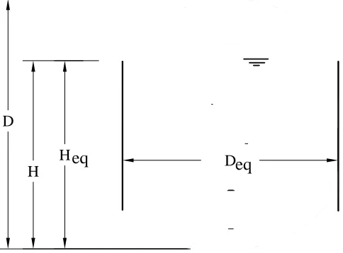
The solution with the idea of “Equivalent Vertical Cylindrical Tank” is used to analyze sloshing characteristics of liquid storage tanks with undisturbed free surface of liquid close to the circular shape. An example for this application can be given to the spherical tanks, in which the free surface is exactly in circular shape. Fig. 3 shows the concept of the equivalence of vertical cylindrical tank to a spherical tank.
H
H
eq
D
eq
DFig. 3 Concept of equivalent vertical cylindrical tank
This approximation is applicable to H/D!0.8. For H/D>0.8, the tank is assumed to behave as if it is full without sloshing effects.
The dimension of the equivalent vertical cylindrical tank, as shown in Fig. 3, is determined as follows:
• Radius of the base circular,Req, is equal to the diameter of the actual undisturbed free surface. • Liquid height, Heq, in the vertical cylindrical tank is determined such that the liquid volume is
maintained.
4.1 Modal properties of sloshing
4.1.1 Modal frequencies
! ! " #
$ $ % & =
eq R
eq H j
eq R
g j cj
' '
( tanh ;
j
=
1
,
2
,
3
,
L
(16)4.1.2 Modal masses
The corresponding modal convective mass ratios are
! ! " # $
$ % & '
=
eq R
eq H j
j j eq H
eq R
T m
cj
m (
( (
tanh ) 1 2 ( 2
;
j
=
1
,
2
,
3
,
L
(17)4.1.3 Base shears
The convective base shear is given by
(
)
!
"= =
1
2
j
cj cj
c m A
The impulsive base shear is determined via
i j
cj T
i m m A
Q !! ! " # $$ $ % & ' =
(
) =1 (19)The total hydrodynamic pressure force is then 2
2
i
c Q
Q
Q= + (20)
4.1.4 Overturning moment
The convective overturning moment is
(
)
!
" = = 1 2 j cj cj cjc m A h
M (21)
where the heights of centroids of convective masses, hcj, is given by
! ! ! ! ! ! " # $ $ $ $ $ $ % & ' ' ( ) * * + , ' ' ( ) * * + , -+ = eq R eq H j eq R eq H j eq R eq H j eq H H cj h . . . sinh cosh 2
;
j
=
1
,
2
,
3
,
L
(22)The height hcj should be limited to
! ! " # $ $ % & ' T cj m m H D
2 due to the tank top restriction. The impulsive overturning
moment is i i j cj T
i m m Ah
M !! ! " # $$ $ % & ' =
(
) =1 (23)where the heights of centroids of impulsive masses, hi, is given by
2 26 . 0 45 . 0 ! ! " # $ $ % & + = eq R eq H eq H eq H i
h (24)
The height hi should also be limited to
!
"
#
$
%
&
''
(
)
**
+
,
-T cm
m
H
D
1
12
due to the tank top restriction. The totalhydrodynamic pressure overturning moment is then determined by
2 2
i
c M
M
M = + (25)
4.1.5 Hydrodynamic pressure on tank wall
The total pressure is given by the sum of an impulsive and a convective contribution: )
( ) ( )
(z pi z pc z
p = + (26)
The impulsive component of pressure is given by the expression:
! ! " # $ $ % & ! " # $ % & '
= eq i +H Req
i H z A R z p / 3 1 )
The convective pressure component is given by a summation of modal terms:
( )
!"
=
# # $ % &
& ' ( # $ % &
'
( )
# # $ % &
& ' (
=
1
cosh 1 2
cosh cos
2 ) (
j
eq R
H j j
eq R
z j cj
A
eq R z
c p
* *
*
+
, (28)
4.2 Frequency of spherical tank
The radius and height of the corresponding equivalent cylindrical tank is 2
2 !
" # $ % & '
=
R H R H R eq
R (29)
2 3
2
! ! " # $ $ % & =
eq R
R H eq
H (30)
The natural frequencies of the tank can be calculated using Eq. (16). Fig. 4 shows the nondimensional natural frequencies for the first and second slosh modes, respectively, in which numerical results (Dodge, 2000) are used for comparison. It can be seen that the approximate results correspond well with the numerical values, except for sloshing of shallow liquid which is not a critical scenario. Spherical Tank Sloshing Frequency
0.0 0.5 1.0 1.5 2.0 2.5 3.0 3.5
0 0.2 0.4 0.6 0.8 1 1.2 1.4 1.6 1.8 2
normalized liquid height
s
lo
s
h
in
g
f
re
q
u
e
n
c
y
1st equivalent 2nd equivalent
1st test 2nd test
Fig. 4 Natural frequency of spherical tanks
5
DESIGN RESPONSE SPECTRA FOR SEISMIC ANALYSIS
The design response spectra used for evaluate the spectral convective acceleration,Acj, and impulsive acceleration, Ai, are constructed based on the procedure specified in the seismic design codes. The design response spectrum with a 3% damping ratio can be used for the impulsive mass, whereas the design response spectrum with a 0.5% damping ratio for the convective masses according to Eurocode 8 (2000).
6
CONCLUSION
A methodology based on the concept of equivalent rectangular and vertical-cylindrical tanks is presented for seismic analysis of liquid storage tanks of general types. Dynamic characteristics of sloshing are calculated for the tanks including modal frequency, modal mass, base shear, overturning moment, and hydrodynamic pressure on the tank wall. Response spectrum method is used for the seismic force calculation.
The proposed approach is comparable with those adopted in the existing seismic design codes for vertical-cylindrical and rectangular tanks. This approach covers general liquid storage tanks in nuclear facilities and can be used for seismic qualification analysis of these tanks.
REFERENCES
API 650, 1998. Welded Storage Tanks for Oil Storage. American Petroleum Institute Standard, Washington, DC.
AWWA D-100, 1996. Welded Steel Tanks for Water Storage. American Water Works Association, Colorado.
AWWA D-103, 1997. Factory-Coated Bolted Steel Tanks for Water Storage. American Water Works Association, Colorado.
AWWA D-115, 1995. Circular Prestressed Concrete Water Tanks with Circumferential Tendons. American Water Works Association, Colorado.
Dodge, F. T., 2000. The new „Dynamic Behavior of Liquids in Moving Containers. Southwest Research Institute. San Antonio, Texas.
Eurocode 8, 2006. Design of Structures for Earthquake Resistance – Part 4: Silos, Tanks, and Pipelines. European Committee for Standardization, Brussels.
IBC 2006. International Building Code Council, Falls Church, Virginia.
NOMENCLATURE
cj
A = modal spectral acceleration of convective
masses;
i
A = modal spectral acceleration of impulsive mass;
p= hydrodynamic pressure on tank wall;
i
p = impulsive pressure on tank wall;
i
p = convective pressure on tank wall;
cj
h = heights of centroids of convective masses;
i
h = heights of centroids of impulsive mass;
H = actual liquid height in horizontal-cylindrical tank;
eq
H = liquid height in equivalent tank;
eq
L = longitudinal length of equivalent tank;
cj
m = modal convective mass of liquid due to
sloshing;
T
m = total mass of liquid in the tank;
M = total hydrodynamic pressure overturning moment;
c
M = convective overturning moment due to sloshing;
i
M = impulsive overturning moment due to seismic load;
Q= total hydrodynamic pressure force on tank wall;
c
Q = convective base shear due to sloshing;
i
Q = impulsive base shear;
R= inside radius of horizontal-cylindrical tank;
eq
R = radius of equivalent vertical cylindrical tank;
eq
W = transverse width of equivalent rectangular tank;
4 )
1 ( 1
; 536 . 8 , 331 . 5 , 841 . 1
! "
+
"
= =
j for j
j j j
# $
$ $
;
!= polar coordinate w.r.t. the sloshing direction;
!= liquid density;
cj