Smart Temperature Sensor Design Using
Voltage Controlled Ring Oscillator
Praveen Kumar Sharma1, Gajendra Sujediya2
Research Scholar, Department of ECE, Rajasthan Institute of Engineering and Technology, Jaipur, India1
Assistant Professor, Department of ECE,Rajasthan Institute of Engineering and Technology, Jaipur, India2
ABSTRACT: Temperature is unique of the supreme significant important physical quantities and is almost common in our day-to-day life. With the scaling down of modern VLSI technologies, more complicate digital circuits have been implemented with a higher clock rate and lower supply voltage, which introduces more constraints for the analog circuits. Therefore, the design of low voltage, low-power analog circuitries has become more important. Because of powered by batteries, the supply voltage is often limited, and the life time of the battery is of great importance for these devices, and all these factors basically address the needs of low-power system building blocks. However, decreased supply voltage restricts signal swing in the circuits and brings difficulties for analog circuit design. In the low-voltage environments, transistor characteristics degrade and the some circuit techniques cannot be used longer thus the low-voltage design is different from the traditional circuit design technique. Ring Oscillator generates the clock signal which is proportional to change in the temperature. A current-starved inverter along with 4-digit adjustable inputs makes ring oscillator frequency-tenable. Voltage level shifter ensures that the counter counts number of its rising edge. The register saves counter output at the very positive edge of external clock. The main difference between two successive outputs of register indicates the temperature.
KEYWORDS: Temperature, VLSI, CMOS, Ring Oscillator
I. INTRODUCTION
Market trends today show devices becoming smaller, mobile, and more battery efficient. This was made possible by the shrinking die sizes and high frequencies achievable due to what we all know as scaling of the transistor. But scaling also means increased power densities that lead to unusual temperature gradients across the chip [2]. In certain areas of the chip high switching activity combined with fast speeds of processing can generate a localized high temperature area on the chip called a “hotspot”. Moreover, current power supply delivery networks, clock gating schemes and dynamic nature of circuits may cause these hotspots to change dynamically. This proves a significant threat to reliability and robustness of the product as well as increases the power consumption of the chip. Hence in addition to external cooling and heat sinks provided by the chip packaging, today there is a need for on-chip thermal monitoring and management of these localized hotspots through use of adaptive systems. All sensors feed information to core control logic which provides a temperature-reducing feedback to very heated circuits. It manipulates the circuit operations performed by parts of the chip; for example it reduces the number of execution operations and increases the number of stall, fetch or completion operations in the overheated part of the circuit and on the other hand increases the number of execution of computational operations in cooler part of the chip.
sensor is sharing information among neighbours with over lapping sensing areas. Smart sensors with signal conditioning and embedded function are more adopted in the market.More importantly, they were relatively inaccurate as compared to the conventional sensors. Typical inaccuracy in mentioned temperature range is 2 C, while the inaccuracy which can be obtained with, such as, a class-A platinum resistor in which range is 0.5 C. The higher accuracy can be achieved by calibration at the multiple temperatures, but this could undo much of the cost advantage of the CMOS smart temperature sensors. Most of the CMOS smart temperature sensors are based on the temperature characteristics of parasitic bipolar transistors.
Generations of Smart Sensor
New type of sensors comes out when older types of sensors fail in unfavourable conditions like weather and temperature conditions. The strategy of implementing expert knowledge from previous technology to a framework of new architecture that supports smaller and smarter sensor was used. The intention is to enable sensor manufacturing to be more flexible and dynamically configurable. In recent years, the increase in the area of nanotechnology has produced interesting materials which provides more opportunity for the development of sensing transduction technology. Older generations of sensors are built on to produce improved performance and extension of its functional capabilities. The technology behind this improvement makes use of advanced calculation, algorithm and signal processing. Example of these includes characteristic functions, weight functions, and inferential calculation of soft sensors its own advanced self-adaptive method for frequency-to-digital conversion. The generation of smart sensor can be categorized into three generations.
First generation: The first generation can be classified according to its receptor. The sensor receptor is trapped in the base sensor. The electronics part of the sensor is usually fused with the transducer.
Second generation: This generation is based on the individuality of component making up the sensor. The electronic element and the sensor node of the sensor are separate in the sensor.
Third generation: In this generation, the electronic element and the sensing node of the sensors are fused together on a single chip, and are relatively small and portable.
III. TEMPERATURE SENSOR
Temperature is most-measured process variable in the industrial automation. The most commonly, temperature sensor was used to convert the temperature value to the electrical value. The temperature sensors are the key to read the temperatures correctly and to control the temperature in the industrials applications.
A large distinction can be made among the temperature sensor types. The sensors differ a lot in the properties such as temperature range, calibrating method, sensing element and contact-way. Temperature sensors consists a sensing element enclosed in the housings of metal or plastic. With help of the conditioning circuits, sensor will reflect the change of the environmental temperature.
+5V
GND
GND OUTPUT
LM34
Figure 3.1: The Circuit diagram for LM34 temperature sensor functional module
It is easy to include LM34 series in the temperature measuring application. Output voltage of the LM34 is linearly proportional to Fahrenheit temperature, and it has the Linear +10.0 mV/°F scale factor that means you will get n*10.0 mV output voltage if environment temperature is n°F.
In the hermetic TO-46 transistor packages, the LM34 series is available packaged, while the LM34C, LM34CA and the LM34D are also available in plastic TO-92 transistor package. LM34D is also available in the 8-lead surface mount small outline package. Now, in our functional module, the LM34H in the metal can package (TO-46) was used in functional module so, it is very important to know that wiring of the sensor should be based on positions of leading pins in the different packages.
Temperature is one of the most important fundamental physical quantity that is a measure of hotness and coldness on a numerical scale. Temperature sensors are widely used in measurement, instrumentation, and control systems. In many applications, it would be attractive to use the temperature sensors which produce readily interpretable temperature reading in the digital format. Such “smart” temperature sensors combine a sensor and interface electronics on the single chip, and are preferably manufactured in a low-cost standard CMOS process. Temperature sensor consist ring oscillator, transmission gate and pulse counter circuit [3]. Pulse counter circuit is designed using d flip flop. The oscillation period (1/f) is converted in to a number of oscillations by applying enable signal of fixed pulse width (PW), and the number of oscillations is stored in the counter to produce the digital output.
IV. DESIGN OF TEMPERATURE SENSOR
4.1.Voltage Controlled Ring Oscillator
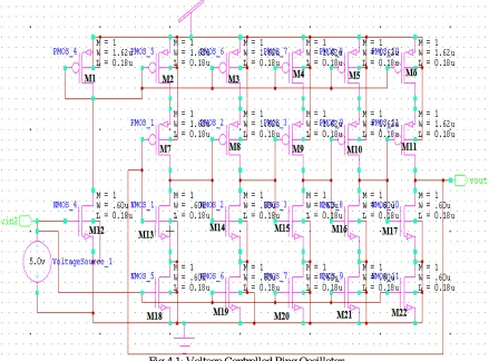
The voltage controlled ring oscillator [1] is used to generate a signal of specific frequency. This VCO is designed using self-bias differential ring oscillator as shown in figure 4.1. A ring oscillator device is composed of odd number of NOT gates and whose output is oscillates between the two voltage levels, representing logic ‘1’ and logic ‘0’.
Fig 4.1: Voltage Controlled Ring Oscillator
This VCO characteristic also depends on the width and length parameters. So the width and length of each MOSFET is chosen very carefully according to the used technology. Length and width of MOS transistor is set according to technology [6].
4.2.Temperature Sensor
The complete diagram of temperature sensor contains two temperature sensor component, level shifter, two buffers, two comparator circuit, three XOR gate and one AND gate. Temperature sensor component is used to take readings simultaneously at given temperature readings VKT and operating voltage (VOP) of system. These readings (TKT,t and
VOP,t) is taken at time t. Low-voltage up level shifters convert the lower voltage, taken from output of temperature
sensor component 1 to higher voltage. Comparator compares each temperature reading with previous temperature reading to produce output. Previous temperature readings are stored in buffer circuit. The two comparator outputs are then passed into an XOR gate circuit, which determines if the temperature(VKT) sense by temperature sensor
component 1, depends at operating voltage VOP (same as VOP) of temperature sensor component 2 or not. If both VKT
and VOP are same then XOR gate gives logic zero output and if different then gives logic ‘1’ output. Circuit diagram of
Fig 4.2: Temperature Sensor
V. RESULT AND ANALYSIS
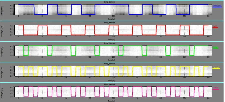
Simulation result and analysis of individual component used to design temperature sensor is discussed below. Temperature sensor is designed using 180nm TSMC technology. Simulated waveform of temperature sensor component is shown in fig5.1. Here input VKT is the temperature reading of temperature sensor component 1, VOP is
than the conventional temperature sensor based on band gap reference. The characteristic of VCRO is drawn between its control voltage and frequency. The frequency range of VCO is calculated as 185 MHz to 810 MHz by its characteristic, with free running frequency of 93 MHz. Power dissipation of Voltage controlled ring oscillator at 1.8V power supply is 438.91µW.
REFERENCES
[1] Shruti Suman, Prof. B.P. Singh, “Ring Oscillator Based Cmos Temperature Sensor Design”, International Journal of Scientific & Technology, ISSN 2277-8616, Volume 1, Issue 4, May 2012.
[2] David Wolpert, And Paul Ampadu, “Exploiting Programmable Temperature Compensation Devices To Manage Temperature-Induced Delay Uncertainty”, IEEE Transactions On Circuits And Systems—I Regular Papers, Vol. 59, No. 4, April 2012.
[3] Sunghyun Park, Changwook Min and Seong Hwan Cho, “A 95nW Ring Oscillator-based Temperature Sensor for RFID Tags in 0.13¹m CMOS”, IEEE International Symposium on Circuits and Systems, 2009.
[4] Poorvi Jain and Pramod Kumar Jain, “Design and Implementation of CMOS Temperature Sensor”, International Journal of Current Engineering and Technology, Vol.4, No.2 (April 2014). [5] Eran Socher, Salomon Michel Beer, and Yael Nemirovsky, “Temperature Sensitivity of SOI-CMOS Transistors for Use in Uncooled Thermal Sensing” , IEEE Transactions on Electron Devices, Vol. 52, No. 12,December2005.