!
"
#"#
$ % %#
&
''' (
Amelioration of the HAD Metamodel for the Modelling of Complex Hybrid Systems
Marcellin Nkenlifack*
LAIA, IUTFV, University of Dschang
LIMMS, National Advanced School of Engineering (Ecole Nationale Supérieure Polytechnique),
Bandjoun, Cameroon [email protected]
Emmanuel Tanyi
Automation and Control Laboratory (ACL), National Advanced School of Engineering (Ecole Nationale Supérieure Polytechnique), University of Yaounde 1
Yaounde, Cameroon [email protected]
Fabrice Fokou
Fotso Victor Institute of Technology Bandjoun, Cameroon [email protected]
Abstract: This article defines a standard for the construction of models of the Hybrid Activity Diagram (HAD). The standard is motivated by the requirements of complex hybrid systems which usually interconnect a large number of components. The improved formalism facilitates the understanding of the HAD metagraph and the implementation of its simulator from the models of hybrid systems. This results from the design of generic connectors and more specific derivatives for flexible connectivity of system components and the definition of static attributes. The effectiveness of the modified metamodel is illustrated by applying it to the modelling of two systems, one of which is the southern network of the Cameroon power system.
Keywords: Modelling with HAD, Hybrid Control System, Complex System, Continuous and Discrete System, UML
I. INTRODUCTION
The Hybrid Activity Diagram (HAD) is an object-oriented tool for the modelling of Automatic Control Systems. It is designed to provide an abstract description of a system which is modelled as a collection of autonomous, localised and dynamic objects. Its formalism and metagraph have been satisfactorily used in modelling a rolling mill for the manufacture of metallic sheets [1], [2], a welding machine and an elevator [3]. However, a number of weaknesses have been identified in the structure of the metagraph when it is applied to the modeling of more complex systems such as power systems [4], [5], [6], [7]). Furthermore, the impkementation of the metagraph is tedious due to the absence of rules or a standard for defining the attributes of the objects represented in a HAD model.
The main concepts of HAD are highlighted in section 2 of this article. This is followed by its anomalies, in section 3. The improved metamodel is presented in section 4. The application of the improved metamodel to the modelling of the southern network of the Cameroon power system is presented in section 5. Such a complex application is an adequate test ground for the improved metamodel. Section 6 presents the conclusions.
II. THE HADMETAMODEL
A. HAD Fundamentals
HAD is an extension of UML ([8], [9]). It is designed to model the discrete and continuous signals which usually constitute the inputs and outputs of hybrid systems as well as the cause-and-effect relationships which describe the functionalities of such systems. The pivotal concepts in HAD are "Object" and "Influence". These are analogous to "Step" and "Transition" in the GRAFCET paradigm (Graphe
Fonctionnel de Commande Etape / Transition [10]). The HAD metagraph is, thus, a diagram which describes the Influences between Objects in a chronological, structured and orderly manner. Each object has dynamic properties and belongs to a specific class. Its formalism is predicated on cause-and-effect relationships as illustrated in figure 1.
Figure 1. Fundamental principle of HAD: causality [1].
Figure 2 shows the HAD model of a rolling mill, taken from [1].
From the model in figure 2, it can be seen that a system is described as a collection of objects which communicate through the exchange of messages.
B. The Initial HAD Formalism
In this section, we present the object classes which are used in constructing a HAD model.
1) The ActivityModul
This objct class represents a family or module of different types of influences. Its sub-classes include "ActivityCause", "ActivityNoEffect", "ActivityEffect" and "ActivityClass".
“ActivityCause” is the class of all external objects which exert an influence on the system (the human operator is a good example of such an entity). “ActivityNoEffect” is the class of all internal objects which do not exert an influence on the system. “ActivityEffect” is the class of all internal objects which exert an influence on the external environment of the system . “ActivityClass” is the class of all internal objects which exert an influence on other internal objects. Figure 3 illustrates some components of an Activity Module.
C
au
se
s
Mechanisms Influences
exerted
The instances of an object which do not exert any influence are referred to as ActivityNoEffect.
Figure 2. HAD Model of a rolling mill [1].
2) “Link Objects" : objects for parallel or selective execution of processes
HAD provides various mechanisms for the modelling of parallelism and conditional selection of alternatives. These structures model branching, fusion, branch-convergence and junctions. The structures include "ActivitySelectON", "ActivitySelectOFF", "ActivityThreadON" and "ActivityThreadOFF". This nomenclature emphasises the fact that the processes triggered by branch-convergence run
in parallel in the form of “threads ». Table 1 presents the differents objects of the HAD meta-graph.
S1 1
S3 2
IN: <BE< S: <BE< OU: “OK”>2>
IN: <1<E1< S: <E1< OP: SetMill ()
Load = 0
OU: “OK”>3> OU: “Process Data Ready”>2>
OU: “Ready for Next Roll”>S1>
IN: <9<S2< S: <9<OR<S2< OP: EndofCycle()
OU: “OK”>EN>
IN: <S3< E1
3
IN: <2< S: <2< OP: SetTemp ()
Tm = To * Exp(-ττττ*t); TempCountDown=0
OU: “OK”>4>
4
IN: <3< S: <3< OP: SetSpeed ()
dt dX f dt
X d J ) X X (
K 2
2 ref− = +
OU: “OK”>S1>
IN: <4<E2< S: <4< AND <E2< OP: SelectProcess () OU: “OK”>5> [Continuous]
“OK”>6> [Reversible] E2
5
IN: <S1< S: <S1< OP: SetTemp(); SetTime();
OpenGap()
Tcd = Tm - Tr
OU: “OK”>7>
IN: <S1<E3<10< S: <S1< OR <10< AND<E3< OP: SetTemp(); SetTime();
OpenGap()
Tcd = Tm - Tr
OU: “OK”>S2>
7
IN: <5< S: <5< OP: FirstRoll(); ReInsertMetal ()
OU: “OK”>8>
8
IN: <7<E4< S: <7< AND <E4<
OP: ReduceGap()
Ref = Om - Op
OU: “OK”>9>
IN: <6< S: <6< OP: Roll () OU: “OK”>10> [Count<<Max] “OK”>S3> [Count == Max]
10
IN: <S2< S: <S2< OP: ReverseDirection()
OU: “OK”>6> S2
OU: “Specimen In Position>8>
E4
OU: “MillReverse”>6>
E3 9
IN: <8< S: <8< OP: SecondRoll()
OU: “OK”>S3>
Figure 3. Sub-classes of "ActivityModule" [1].
3) Description of the Static attributes of Link Objects a) Structure of "ActivitySelectON" .
The object in figure 4 allows one process at the input to trigger three possibilities at the output. Each cell below the horizontal bar represents one of the three possibilities. The letter “S” signifies “Selection”.
Figure 4. Instance of "ActivitySelectON" with one input and three outputs
(selection divergence).
b) Structure of "ActivitySelectOFF".
The object in figure 5 is the structural complement of the precedent object in figure 4. It is a convergence point for several conditional processes. Each of the three cells above the horizontal bar represents one of the three possibilities.
NB : The structural description of the « ActivitySelect » class of objects is similar to « ActivityThread”. The only
difference is in their functionality. “ActivitySelect” triggers conditional processes simultaneously, but only one is validated and selected.
Figure 5. Instance of "ActivitySelectOFF" with three inputs and one
output (selection convergence).
C. Limits of the basic HAD formalism
1) Observation
The use of HAD in modeling a variety of systems has led to the conclusion that while the formalism is adequate for the modeling of systems having a small number of components (rolling mill; welding machine), it is inadequate for systems which interconnect a large number of components. Power systems are a good example of such high connectivity systems. This is the main motivation for the re-design of the formalism to provide a wide range of link objects which facilitate model connectivity.
2) Problem Statement for the design of link objects The initial formalism has certain anomalies due to the lack of precision in the definition of static properties. This ambiguity results in multiple representations of the same object, as illustrated in figure 6. All of these three representations were used in the HAD model of the rolling mill.
Table I. Components of the HAD Metamodel for parallelism and Selection of alternatives
Domain Element Meta-graph
Type Representatio n
Attributes
ActivityThreadON (example : triggering of two output processes )
Node
-identifier
- List of messages received at the input
-variable for the logical synchronization of messages at the input
* The message ``OK ’’ is sent to all outputs
ActivityThreadOFF ( example: end of two parallel processes at the input)
Node
-identifier
- List of messages received at the input
-variable for the logical synchronization of messages at the input
* The message ``OK ’’ sent to all outputs
ActivitySelectON (example : conditional selection of one of three possible alternatives)
Node
-identifier
- List of messages received at the input
-variable for the logical synchronization of messages at the input
- logic condition for the selection of the output * The message ``OK ’’ sent to all corresponding outputs
ActivitySelectOFF (example : convergence of alternatives for selection)
Node
-identifier
- List of messages received at the input
-variable for the logical synchronization of messages at the input
* The message ``OK ’’ sent to all outputs
Combination of -identifier
ActivityClass ActivityCause
two alternative processes at the input and the triggering of one process at the output
Node - List of messages received at the input
-variable for the logical synchronization of messages at the input
* The message ``OK ’’ is sent to all outputs
(6.a) [HAD model of rolling mill]
(6.b) [HAD model of rolling mill]
(6.c)
Figure 6. Different representations of "ActivitySelectOFF" with two
inputs and one output.
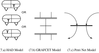
The representations in (a) and (b) of figure 6 do not conform to the principle outlined in section II-B-3-b. Multiple representations of the same object (like in figure 7.a) may lead to different interpretations of system functionality and errors in the properties of objects. This also has serious consequences for the system developer - tedious software design and unnecessarily complex, long and incoherent source code.
(7.a) HAD Model (7.b) GRAFCET Model (7.c) Petri Net Model
Figure 7. Different representations of a distribution junction with two
inputs and two outputs.
III. AMELIORATION OF THE FORMALISM
D. Constraints for the re-design of the formalism
It is required to define and impose a standard which must apply to all link-objects, in order to enhance clarity, limit the multiplicity of representations and facilitate the implementation of the simulator of HAD models. Since links are tools for interconnecting objects, the generic object class “ActivityConnect” was designed to represent links. The different types of links for parallel or selective functionality are instances of this generic class.
1) Structural Constraints (rules for the construction of link objects)
• Inspired by the principle in section II-B-3-b, all instances of “ActivityConnect” are designed to have a horizontal bar to serve the dual purpose of separating the input from the output and facilitating the identification of the link object (figure 8).
Figure 8. Horizontal bar as identifier of “ActivityConnect”.
• Cells are assigned to the input zone above the horizontal bar depending on the number of branches or input processes, as indicated in figure 9.
Figure 9. Three cells at the input of an “ActivityConnect”.
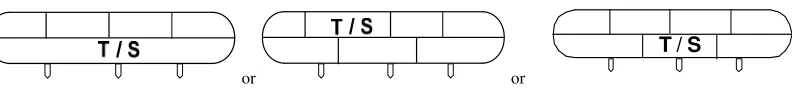
• Cones are located at the lower extremity of the output zone. The number of cones depends on the number of output branches. The output zone itself is reserved for the name of the object sub-class, “S” for “ActivitySelect” and “T” for “ActivityThread”. Figure 10 illustrates the various rules.
Figure 10. Link-objects with three input branches and three output
branches.
With this new formalism, the models of figures 6 and 7 are modified as shown in figures 11 and 12.
Figure 12. The improved Process Distribution Junction.
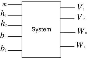
The new formalism has been used to model the liquid-level system shown in figure 13. The functional specifications of the system are given in [11]. When the system operator presses the button “m” the inlet valves V1 and V2 open and the two tanks start filling up. When any tank is full, as detected by the corresponding level sensor h1 or h2, the corresponding outlet valve W1 or W2 opens to evacuate the contents of the tank. When any of the tanks is empty, as detected by the corresponding level sensor b1 or b2, the corresponding outlet valve W1 or W2 closes.
The functional block diagram of the system is shown in figure 14.
Figure 13. Liquid-level control system [11].
V
1W
1h
1m
h
2b
2V
2W
0b
1Figure 14. Functional Block diagram of the liquid-level control system.
It should be noted that the dynamics of the motors Mo, M1 and M2 constitute the continuous-time component of the model.
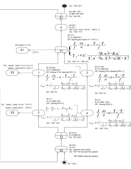
Each of the valves is actuated by a motor. The shaft of the motor is coupled to the valve stem. The motion of the motor and valve stem is described by the differential equation.
r r em
r t
f T T dt
d f
J −
= Ω + Ω
(1)
And the electromagnetic torque which drives the motor shaft and valve stem is given by :
( )
(
)
(
n
X
)
n
(
R
X
)
n
X
n
R
n
R
V
T
S S
S S
em
n n K
n 2
2 2 2 2 2 2 2
2 2
2 2 2
2 1
. 2 .
. .
.
+ +
−
+ −
= (2)
Where,
f
r frictional torque constant ;J
t is the combined moment of inertia of the motor shaft and load ;R
2andX
2 are the resistance and reactance of one phase of the motor ;n
s is the synchronous speedDetails of these equations are available in [12].
The HAD model of the hybrid system is shown in figure 15.
2) Logical Contraints
The new entities added to HAD impose other constraints which are a logical consequence of two factors – the structure of sequential diagrams and the need to reduce the size of diagrams.
a) Structure of sequential diagrams
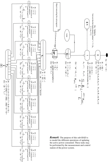
Whatever the paradigm used in describing sequential systems, the notion of sub-graph is encountered. This is the case with Logigrams, Grafcet and Petri nets. The sub-graph is a construct which facilitates the hierarchical modeling of a system and reduces the complexity of diagrams. A sub-graph, which is represented as a single object, encapsulates the model of part of a sequential system and can be incorporated into the main model. This fact has motivated the notion of Sub-HAD which is a sub-graph of HAD. The various conceptual entities associated with sub-HAD are presented in table 2.
b) Reduction of the size of diagrams
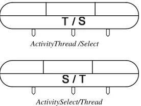
ActivityThreadON has two functionalities when two proceses are received at its input- either activate both processes (parallelism) or activate one of the processes (conditional selection). For this reason two “ActivityConnect” objects have been created. These are:
• "ActivityThread/Select" which receives parallel processes but selects only one and switches it to he m :
output. Figure 16 shows an "ActivityThread/Select" with three inputs and three outputs.
• "ActivitySelect/Thread" which ends the execution of conditional processes at its input and activates
parallel processes at its output (this is similar to “ActivitySelectOFF”). Figure 16 shows an “ActivitySelect/Thread” with three inputs and three outputs.
Figure 16. New formalism of "ActivitySelect/Thread" and "ActivityThread/Select").
Consequently, when an "ActivityThread" is followed by an "ActivitySelect" the two entities can be replaced by a single "ActivityThread/Select" and vice-versa, as shown in
figure 17(a) which is an excerpt of the model of the southern network of the Cameroon power system [13].
c) Rules of fusion of two "ActivityConnects"
The fusion in figure 17 is possible only if none of the "ActivityConnect" objects is associated with an operation or if only one object has an operation. In the latter case, the single object obtained by fusing the other two is assigned the operation which existed between the fused objects. When both objects are associated with operations, fusion is not possible because such fusion may modify the order of execution of the two operations. Note that in the previous formalism, the links described above would have had several representations. This is the case with the "Activity Thread/Select" presented in figure 18. In table 2, the formalisms of "ActivityConnect" objects are presented, based on the proposed metagraph for each new element.
f
(Figure 17.a : before fusion)
f
(Figure 17.b : after fusion)
Figure 17. Fusion of an “ActivityThreadOFF” and an "ActivitySelectON".
ActivityThread /Select
Figure 18. Alternative representations of “ActivityThread /Select” in the former formalism.
Table II. Improved components of the HAD metagraph for parallelism and conditional selection of processes: basic "ActivityConnect" objects
Domain Element Meta-graph
Type Representation Attributes
ActivityThreadON (example : triggering of two output processes )
Summit -identifier
- List of messages received at the input
-variable for the logical synchronization of messages at the input * The message ``OK ’’ is sent to all outputs
ActivityThreadOFF ( example: end of two parallel processes at the input)
Summit -identifier
- List of messages received at the input
-variable for the logical synchronization of messages at the input * The message ``OK ’’ is sent to all outputs
ActivitySelectON (example : conditional selection of one of three alternatives)
Summit -identifier
- List of messages received at the input
-variable for the logical synchronization of messages at the input * The message ``OK ’’ is sent to all corresponding outputs
ActivitySelectOFF (example: end of selection of one of three alternatives)
Summit -identifier
- List of messages received at the input
-variable for the logical synchronization of messages at the input * The message ``OK ’’ is sent to the output
Combination of two alternative processes at the input and one process triggered at the output
Summit -identifier
- List of messages received at the input
-variable for the logical synchronization of messages at the input * The message ``OK ’’ is sent to the output
Combination of two alternative processes at the input and two processes triggered at the output
Summit -identifier
- List of messages received at the input
-variable for the logical synchronization of messages at the input - logic condition for the selection of the output
* The message ``OK ’’ is sent to corresponding outputs
End of two parallel processes at the input and the triggering of one of the processes at the output
Summit -identifier
- List of messages received at the input
-variable for the logical synchronization of messages at the input - logic condition for the selection of the output
* The message ``OK ’’ is sent to corresponding outputs
A HAD sub-diagram for the modeling of a subsystem
Summit - List of messages received at the input
-variable for the logical synchronization of messages at the input - logic condition for the selection of the output
* The message ``OK ’’ is sent to corresponding outputs
IV. APPLICATION OF THE NEW “ACTIVITYCONNECT”
FORMALISM TO THE MODELLING OF A POWER
SYSTEM
The analysis of power systems is of fundamental importance due to the pre-dominance of such systems and their role in the economic development of nations. This justifies the interest that several researchers have shown in various aspects of power systems ([14], [15], [16]).
The power system modeled in this section consists of a hydro-electric generation station and two thermal plants
supplying three consumption nodes A, B, C, each characterized by a load. The two thermal stations serve as back-up stations which are put into service when the energy produced by the hydro-electric station is insufficient to meet the demand.
In such situations, the smaller of the two thermal stations is first switched on. If the power output is still insufficient, the second thermal station with a higher generation capacity is also switched on. If the combined output of the hydro-electric station and the two thermal plants is still insufficient to meet the demand, then load shedding is progressively applied by disconnecting some of the low-priority loads from
or or
A, B and then C, in that order, until equilibrium is restored between supply and demand. In designing the model of the
system, the input and output variables were first identified and represented in the functional block diagram of figure 19.
;
Figure 19. Sub-HAD component of the HAD Model.
;
2
0
=
=
j
C
CjS
DTC;
2
0
=
=
j Bj
C
S
DTB;
2
0
=
=
j
C
AjS
DT A;
3
1
=
=
i DTi
S
D;
D S− = ∆
;
1 1=S −D ∆
;
1
1
S
S
S
= H+ th;
2 2=S −D ∆
;
2
2
S
S
S
= H+ th;
1 2 12=
S
th−S
th∆
;
2 1
3
S
S
S
S
= H+ th+ th;
3 3=S −D ∆
); 0 12 . 0 2 . 0 1 ( ) 0 2 . 0 1 .( 0
3> ∆ > ∆ < +∆ > ∆ > ∆ >
∆
); 0 12 . 0 2 . 0 1 ( ) 0 2 . 0 1 .( 0
3> ∆ < ∆ > +∆ > ∆ > ∆ <
∆
.); 0 3 ( ) 0 2 . 0 1 .( 0
3> ∆ < ∆ < + ∆ <
∆
Figure 20. HAD Model of the Power System.
The input variables consist of the switches and push-buttons through which the human operator controls the system. The output variables include the circuit-breakers and the different states or configurations of the power system. Excerpts of the Sub-HAD and HAD models are shown in figures 20 and 21 respectively.
The link-objects in the new formalism are clearly identifiable in the diagrams of figures 20 and 21. They also enhance the understanding of the system operation and reduce
d
0d
1R
1R
2k
1k
0k
2k
ijd
2d
ijR
0m
1m
0m
2Figure 21. Functional block diagram of the power system.
Key: R0, d0, k0 represent the state of the hydro-electric station, its
circuit-breaker and the switch of the circuit-circuit-breaker; kij, dij represent the switch and
circuit-breaker at node i, on branch j; m0, m1, and m2 represent the switching of the hydro-electric station and the two thermal stations.
V. CONCLUSION
In this article, the link-objects of the HAD metamodel have been re-designed to facilitate the modeling of systems with a high connectivity of components. Power systems are a typical example of such high connectivity models. The re-design has endowed HAD with a class of objects, “ActivityConnect”, which represents all generic connectors or links. Sub-classes or derivatives of this object class have more specific connectivity properties which provide great flexibility and precision in the way components are interconnected. The concept of Sub-HAD has also been introduced to enable a complex system to be sub-divided into smaller sub-systems which can be incorporated into the main model. This is a useful mechanism which facilitates the hierarchical modeling of complex systems and reduces the size of HAD diagrams
VI. REFERENCES
[1] M. Nkenlifack and E. Tanyi, “An extended UML for the modeling of hybrid control systems”, in Burnham K.J., Haas O.C.L.(Editors), Proc. of the sixteenth International Conference on Systems Engineering (ICSE2003), Coventry, UK, 9-11 September 2003, Vol.2, pp.681-686, ISBN 0-905949-91.
[2] M. Nkenlifack and E. Tanyi, “Hybrid Activity Diagrams: Extending UML for the Modeling of Hybrid Systems”, Poster in ECOOP’03, 17th European Conference on Object –Oriented Programming, July 21-25, 2003, Darmstadt University of Technology, Germany,
http://www.st.informatik.tu-darmstadt.de:8080/ecoop/posters/index.phtml - Site Web poster.
[3] M. Nkenlifack, "Modélisation objet et développement d’un atelier de simulation des automatismes industriels hybrides", PhD Thesis, Dept. of Computer Engineering, National Advanced School of Engineering (Ecole Nationale Supérieure Polytechnique), University of Yaounde I, Cameroon, 2004.
[4] J. Lienou, M. Nkenlifack, E. Tanyi and T. Noulamo, “A generic multi agent-based platform for reliable diagnostic by DGA”, Advances in Computer Science and Engineering Journal, Volume 5, Issue 1, Pages 11 - 23 (August 2010), Pushpa Publishing House, ISSN 0973-6999.
[5] T. Noulamo, E. Tanyi, M. Nkenlifack and J. Lienou, “Domain Specific Model and Generic Architectures for Control and Monitoring of Dynamic Systems”, Advances in Computer Science and Engineering Journal, Volume 4, Issue 1, Pages 55 - 75 (February 2010), Pushpa Publishing House, ISSN 0973-6999, India.
[6] M. Nkenlifack and E. Tanyi, “An object oriented simulation platform for hybrid control systems”, Analysis and Design of hybrid systems (ADHS) 2003, Proc. of the IFAC International Conference, St Malo, France, June 16-18 2003, Edited by S.Engell, H Gueguen&J.Zaytoon, ISBN 0-08-04044094-0.
[7] J. Zaytoon, Systèmes Dynamiques Hybrides, Traité Systèmes automatisés, Information Commande et Communication, Hermes, Paris, 2001.
[8] //www.omg.org, Site Web de l’OMG contenant le manuel de référence UML 2.0, 2008.
[9] M. Flower, UML Distilled, Second edition, Addison-Wesley Longman, Inc, 2000.
[10] CEI-IEC (International Electrotechnic Commission), GRAFCET specification language for sequential function charts, International Standard, IEC 60848, 2002.
[11] R. David and H. Alla, Du Grafcet au Réseaux de Petri, série automatique, 2em édition revue et augmentée, édition HERMES 1992, 1997 500 pages(271).
[12] T. Wildi and G. Sybille, Electrotechnique, 3em edition, DeBoeck Université.
[13] F. Fokou, "Metamodele UML–HAD, Analyse et Mise en Œuvre dans le cadre de la Commande des Réseaux Electriques : cas du Réseau Sud AES SONEL Cameroun", Bachelor Thesis, Electrical Engineering, IUT FV of Bandjoun, University of Dschang, Cameroon, 2009.
[14] Y. Pelenc, Appareillage électrique d’interruption à haute tension, Technique de l’ingénieur Doc. (4700, 4701, 4702, 4703.), 1988, 58 pages.
[15] E. Kabadanian, "Problèmes de la coupure d’un circuits", article datant du 27 Décembre 2003, unpublished
![Figure 1. Fundamental principle of HAD: causality [1].](https://thumb-us.123doks.com/thumbv2/123dok_us/708906.1079104/1.612.331.543.428.477/figure-fundamental-principle-causality.webp)
![Figure 2. HAD Model of a rolling mill [1].](https://thumb-us.123doks.com/thumbv2/123dok_us/708906.1079104/2.612.107.498.74.589/figure-model-rolling.webp)
![Figure 3. Sub-classes of "ActivityModule" [1].](https://thumb-us.123doks.com/thumbv2/123dok_us/708906.1079104/3.612.103.513.403.744/figure-sub-classes-of-activitymodule.webp)