107 |
P a g e
www.ijarse.com
DOCKING A MOBILE ROBOT FOR CHARGING USING
LABVIEW
Shanker Ganesh RadhakrishnaPrabhu
Department of MME, LNMIIT, (India)
ABSTRACT
Autonomous robots are trying to become self sufficient day by day and this paper presents an attempt towards
making a robot self-sufficientat least in its power requirements. Necessary electrical design of a system is done
for the robot to locate a charging/docking station, go towards it and recharge its battery when necessary
without manual intervention. The results of the experiments performed on the system are also presented.
Keywords: Automatic Docking, LabVIEW, Mobile Robot.
I INTRODUCTION
A docking station for the National Instruments DaNI robot was designed using the requisite hardware and
software systems. The mechanical design of the hardware used in this paper is from a previous work undergone,
which is presented in [1]. Its task was to enable the robot to charge automatically when the robot’s battery is
below a certain threshold. The hardware consists of the docking mechanism and the sensors were integrated
with circuits; several such circuits were mounted directly onto the robot. Circuits for auxiliary supply, automatic
switching of power supply and to measure voltage were designed. The software controls the robot by
continuously monitoring the battery levels and executing a docking algorithm, which makes decisions with the
help of IR LED- Photodiode pairs and optical encoders as sensors. The voltage sensors were used to detect if the
robot is docked.The robot has a built-in FPGA and RT processor along with quadrature optical encoders and
two 152 rpm dc motors. The four wheeled robot uses the differential drive mechanism for movement. National
Instruments LabVIEW is used for graphical coding, National Instruments Multisim 11.0 is used for electrical
circuit design.
II PREVIOUS WORKS
In [2] a camera is used to locate the docking station and a laser beacon is used to calculate the angle of rotation
of the robot. Once the robot is docked, an IR LED mounted on the station sends a signal to the robot controller.
Battery voltage level is also monitored continuously to check for docking.
In another system a camera is again used extensively for locating the docking station aswell as for aligning of
the robot correctly. The camera determines the angle and distance from the target by calculating the dimensions
of a known shape placed above the station and later formulates a virtual spring model[2]. Kim et al. [4] tried to
solve the same problem using simple infrared sensors on a circular shaped robot. The docking station is
108 |
P a g e
www.ijarse.com
which IR sensor receives data and from which IR LED, the position and angle of approach is calculated. A
unique coding system is used to differentiate between the signals from the IR LEDs.
Wu et al. [7] goes a step further by designing a docking station for exchanging a discharged battery with a
charged one. A variety of sensors are used in the process; a magnetic tape used for guidance, optical sensor used
for detecting the state, and other sensors for rotation of carrier as well as for grabbing arms in the docking
station. The carrier rotates to align it with the orientation of the robot while a grabber is used to hold the robot
steady while the battery exchange happens through a push-pull device. Separate electrodes are also provided to
power the robot at the time of exchange.
Most of the solutions use a combination of sensors for docking. Camera, laser beacon and IR sensor in
Silverman et al. [2], camera and infrared sensors in Luo et al. [3] and magnetic sensor, optical sensor and
camera in Wu et al. [7]. Kim et al. [4] and Wu et al. [7] have complex docking mechanisms which makes them
easily susceptible to mechanical faults. The docking mechanisms in [2], [4], [5], [6] and [7] contains some kind
of power consuming controller at the docking end which has to be left turned on continuously.
III THE SYSTEM
In the previous work [1], a mechanical design of the docking station is already presented. In the next step, to
enable docking, the already present optical encoder is used to locate the robot in a space and using those data,
the robot is driven towards a predefined location. Two IR sensors are placed next to the front wheels for this.
From there, using another 4 infrared sensors the robot tracks a line which leads the robot towards the docking
station (figure 1).
Circuits were designed for switching over between batteryto external source. The external source circuit takes
an input of 220V AC from the wall socket and converts it into a 12V DC (using a rectifier). The design is done
such that the present battery charger adapter is not modified at all. A voltage sensor is also added to the circuit
to enable the robot know whether the battery is fully charged or exhausted. Figure22: Power circuit
109 |
P a g e
www.ijarse.com
IV METHODOLOGY
IR LED-photodiode sensors were used to align the robot correctly with respect to the docking station. A
non-reflective line was drawn from the docking station which was 1.4 m in length(calculated after accommodating
maximum possible errors). Using the optical encoders on the robot, the robot would know its position in the 2D
space at any time. The robot would also know the coordinates of a predefined point in the line. When the battery
level was low, the robot would move towards the point on the line. The point was given such that even after the
possible odometric errors, the robot should be able to able to steer itself to some part of the line. Once the line
was reached, the robot would move along the line towards the docking station. The robot would follow the line
until, the battery started charging. Once the battery charging was finished, the robot would correct for the
odometric errors by updating its position to the coordinates of the docking station. This would help the robot to
come back easily to the docking station at a later point of time.
Another problem which had to be taken care of was, when the robot reaches the line, how would it know in
which direction it should move so that it can reach the station. The robot knows in which direction it should
move, to reach the point on the line. Based on the coordinates of the point of the line and the coordinates from
which the robot started to look for the line, the robot could tell which direction it should rotate in order to reach
the station.
Figure2 shows the possible positions on the robot with the docking station at the centre of the figure. The initial
x coordinate, y coordinate and the angle with respect to x axis is given as inputs to the VI. The robot is at (0,0)
and oriented towards the positive x axis. The point which is supposed to be reached by the robot is given as
110 |
P a g e
www.ijarse.com
2 2
) ( )
(lx rx ly ry
d where d is the distance, (lx ,ly) is the point on the line and (rx,ry) is the robot
coordinates. Then the slope of the line is calculated as
x y 1
cos along with the value of and .
In figure 2 the possible positions of the robot with respect to the point on the line is shown. For every quadrant,
the updated value of Ѳ is shown. If and are both greater than 0 or if is negative and is
positive, the calculated value of Ѳ is not altered. In the next two quadrants, the obtained value of Ѳ is not the
actual rotation angle as LabVIEW generates only angles between 0º and 180º. Therefore the angle is subtracted
from 360º which is later used. To know whether the robot is in any of the two quadrants, the sign of and
are checked. If both are negative or if is negative and is positive the angle is subtracted form
360º.
The next step is to calculate the angle the robot should rotate based on its current orientation. If Ѳ obtained from
above is less than A(orientation angle), Ѳ is subtracted from A and the robot rotates the new angle (a) in the
anti-clockwise direction. Else the robot is rotated in the anti-clockwise direction for the difference.
Ams counter is used in the program which start counting when the robot starts rotating and it is multiplied by a
rotational velocity of the robot to obtain the angle rotated. To convert the wheel velocity to robot rotational
velocity a multiplication factor of 7.8 is used. This factor is found by trial and error method as it was impossible
to calculate the extremely unpredictable slip occurring on the wheels when the wheels skid to rotate. The robot
stops rotating when the measured angle equals to the calculated angle. At this point the robot will be oriented
towards the point on the line.
Once the robot is looking towards the line, the robot should move forward till it reaches the line. Again based on
the Ѳ and , a decision is made on which sensor to look for is made as follows. If the angle is less than 90º
and is positive or if angle is greater than 90º and is negative, look for output of front left sensor (L).
If the angle is less than 90 and is negative or if angle is greater than 90 and is positive, look for
output of front right sensor (R).
Once that decision is made, the robot stops when the sensor shows a high reading. Now the robot has to go
forward till the corresponding next sensor crosses the line. To do this, a count variable is initiated and the value
of 0 represents the left sensor and the value 1 represents right sensor. Once the decision on which front sensor is
to be looked for is made, the value of the count variable is assigned 0 or 1.
If the variable returns 0, the code initiates to look for L1 sensor and the following operation is done. Another
counter is initiated to let the program know how many times the sensor detect after every iteration of the while
loop. The count value greater than zero means that the sensor has shown high readings at least once. This means
that the sensor is already on the line. But the robot has to stop only after it crosses the line and so, at the instant
where the variable shows a value over 0 and the sensor gives a low reading, the robot stops. Similarly if the
111 |
P a g e
www.ijarse.com
the other sensor. The robot is asked to move further forward for another 500ms to let the robot be in a better
position to bring all sensors above the line after it rotates.
The direction the robot should rotate in order to align along the line and also towards the docking station is
decided as follows. It should either rotate left or right from alignment. It is found by considering the coordinates
of the point on the line and the initial coordinates of the robot. If lx(point x coordinate) is greater than Rx(robot x
coordinate) and if ly(point y coordinate) is greater than Ry(robot y coordinate) or if lx(point x coordinate) is less
than Rx(robot x coordinate) and if ly(point y coordinate) is greater than Ry(robot y coordinate) rotate clockwise.
In the other condition rotate counter clockwise till all the sensors are on the line or if at least one sensor pair (L1
and L2 or R1 and R2) is on line. When all the sensors are on the line the robot stops.
At this point the robot should have reached on the line and be looking towards the docking station. Now the
robot has to track the line till docking station is reached. For this the robot monitors the output of its sensors in
pairs. At once, it looks for sensors L1 and R2, if either of the sensors gives a low reading, it means the robot is
not exactly above the line. Therefore the robot rotates clockwise till both are on line. It again goes forward until
either of the next pair of sensors i.e. R1 and L2 is outside the line. To correct that error, the robot rotates in the
counter clockwise direction until both are on the line. Since the robot skids unpredictably while rotating, a new
code segment is also added which considers that scenario as well. When the robot rotates, there is a possibility
that the sensor pairs on each side can end up outside the line. When this happens, depending on which pair, the
following logic is executed. If L1 or L2 is out of line, the left wheels is run at a speed higher than the right
wheels until the sensor L1 is back on the line. After this, the robot moves forward till sensor R1 is just outside the
line. Then the robot rotates in the anti-clockwise direction till all the sensors are on the line. A similar operation
is followed if the other sensor pair also displaces due to skidding. This process continues until the voltage
sensor detects charging. In that condition, the robot has touched the docking station contacts. But as the robot is
not yet docked completely, the robot is asked to go further forward for 1 sec and then stop. Now the robot is
completely docked and its battery is charging. Then the robot is asked to wait till the battery finishes charging.
Once charging is completed, the robot will go back to follow its objective until the battery charge is almost
empty again.
V EXPERIMENTS AND RESULTS
The robot was kept in all the 4 quadrants (figure2) assuming the point on the line was at the centre and with 3
different orientations(0º, 135º, 225º). The calculated angle of rotation, corrected angle of rotation and actual
angle of rotation were tabulated (table 1) for every robot position.
112 |
P a g e
www.ijarse.com
Rx(cm) Ry(cm) A(º) Calculated
angle (º)
Corrected
angle(º)
Actual
angle(º)
Direction
of
rotation
Expected
angle
Result
0 0 0 45 45 45 CCW 45 OK
0 0 135 45 45 90 CW 90 OK
0 0 225 45 45 180 CW 180 OK
200 0 0 135 135 135 CCW 135 OK
200 0 135 135 135 0 - 0 OK
200 0 225 135 135 90 CW 90 OK
200 200 0 135 225 225 CCW 225 OK
200 200 135 135 225 90 CCW 90 OK
200 200 225 135 225 0 - 0 OK
0 200 0 45 315 315 CCW 315 OK
0 200 135 45 315 180 CCW 180 OK
0 200 225 45 315 90 CCW 90 OK
Since the experiment of rotation in various quadrats were already performed, this experiment concentrated
mainly on the rotation towards the line, line tracking, stopping after docking, entry angle and position and
disconnecting after recharging was completed. In every case the robot’s voltage level was measured and the
robot was connected to the docking station manually to find the voltage after docking. These voltages were used
to set the voltage level in the program (to know whether docked or not and to set the disconnection voltage
level).
1. The robot was placed at coordinates (0,0) and orientation as 0° and the program was run. It was
verified whether the robot turns towards the right after reaching the line and finished docking.
2. Then the robot was placed at (150,0) and orientation as 0° and checked if the robot rotated towards the
right and successfully docked.
3. The rotation towards left was checked by keeping the robot in the other two quadrants.
113 |
P a g e
www.ijarse.com
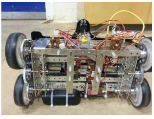
tracked the line satisfactorily and stopped after docking. The entry angle and position did not go over ±5° and
±2mm. The robot also came back after the given voltage level is reached. The image of the robot going towards
the docking station is given in figure 3.
VI CONCLUSION
The robot was able to locate the docking station and charge automatically when required. All of this was made
possible using simple IR LED-Photodiode sensors, voltage level sensor and optical encoders as sensors. The
docking station turned on only when the robot entered the station and this helped in power saving. There are no
electrical actuators used on neither the robot nor the docking station. Only passive devices such as springs and
bearing were used to enable various degrees of freedom. The robot was able to dock at high accuracy and
precision in all the trials taken.
In the future, an extra support (possibly another rod end bearing or something similar) should be added to the
docking mechanism to not let it hit back on to the surface when the robot disengages. Sensors more reliable
than IR LED- Photodiode sensors can be used to decrease the setting up time of the whole system.
REFERENCES
[1] RadhakrishanPrabhu, S.G., “Design of a docking station for a Mobile Robot,”Intl. J. of Advanced Technology in
Engineering and Science, vol 3, issue 1, pp.- 224-230, Jan 2015.
[2] Silverman, M.C.; Nies, D.; Jung, B.; Sukhatme, G.S.; , "Staying alive: a docking station for autonomous robot
recharging," Robotics and Automation, 2002. Proceedings. ICRA '02. IEEE International Conference on , vol.1, no., pp.
1050- 1055 vol.1, 2002
[3] Luo, R.C.; Liao, C.T.; Su, K.L.; Lin, K.C.; , "Automatic docking and recharging system for autonomous security robot,"
Intelligent Robots and Systems, 2005. (IROS 2005). 2005 IEEE/RSJ International Conference on , vol., no., pp. 2953-
2958, 2-6 Aug. 2005
[4] Kim, K.H., Choi, H.D., Yoon, S., Lee, K.W., Ryu, H.S. Woo, C.K., Kwak, Y.K..; “Development of docking system for
mobile robots using cheap infrared sensors”. Proceedings of the 1st International Conference on Sensing Technology,
pp. 287–291, Palmerston North, New Zealand, 21–23 November 2005
[5] S. Roh, J. Park, Y. Lee, Y. Song, K. Yang, M. Choi, H. Kim, H. Lee, and H. Choi,; , "Flexible docking mechanism using
combination of magnetic force with error-compensation capability," Automation Science and Engineering, 2008. CASE
2008. IEEE International Conference on , vol., no., pp.697-702, 23-26 Aug. 2008
[6] S. Roh, J. Park, Y. Lee, Y. Song, K. Yang, M. Choi, H. Kim, H. Lee, and H. Choi, "Flexible Docking Mechanism with
Error-Compensation Capability for Auto Recharging System of Mobile Robot," Intl. J. of Control, Automation, and
Systems, vol. 6, pp. 731-739, Oct. 2008.
[7] Y. Wu; M. Teng; Y. Tsai; , "Robot docking station for automatic battery exchanging and charging," Robotics and
Biomimetics, 2008. ROBIO 2008. IEEE International Conference on , vol., no., pp.1043-1046, 22-25 Feb. 2009
[8] F. Ferreira; R. Ventura; “Autonomous docking of a tracked wheels robot to its tether cable using a vision-based
algorithm”, Workshop on Robotics for Disaster Response, ICRA 2009 - IEEE International Conference on Robotics and