IJEDR1504005 International Journal of Engineering Development and Research (www.ijedr.org) 1 ________________________________________________________________________________________________________ Abstract - In this paper, a simplified control algorithm for a three-phase, unified power quality conditioner (UPQC) is presented to compensate for supply voltage distortions/unbalance, supply current harmonics, the supply neutral current, the reactive power and the load unbalance as well as to maintain zero voltage regulation (ZVR) at the point of common coupling (PCC). The UPQC is realized by the integration of series and shunt active filters (AFs) sharing a common dc bus capacitor. The shunt AF is realized using a three-phase voltage source inverter (VSI) and the series AF is realized using a three-phase, three leg VSI. A dynamic model of the UPQC is developed in the MATLAB/SIMULINK environment and the simulation results demonstrating the power quality improvement in the system are presented for different supply and load conditions.
IndexTerms - Active Power Filter (APF), UPQC, Harmonics Voltage Sag, Voltage Swell, Power Quality.
________________________________________________________________________________________________________
I.INTRODUCTION
The main objective of electrical utility corporations is to produce their customers with uninterrupted sinusoidal voltage of constant magnitude. But this can be turning into more and more difficult to do, as a result of the size and number of non-linear and poor power factor loads like adjustable speed drives, computer power supplies, furnaces and traction drives are increasing speedily. As a result of their nonlinear nature, these solid state converters cause excessive neutral currents in three phase four wire systems. Moreover, in the case of the distribution system, the load on the system is rarely found to be balanced.
In the past, the solutions to mitigate these known power quality issues [1] were through using typical passive filters. however their limitations like, fixed compensation, resonance with supply impedance and therefore the problem in calibration time dependence of filter parameters have ignited the necessity for active and hybrid filters [2]–[4]. The rating of active filters is reduced through augmenting them with passive filters [5], [6] to create hybrid filters that reduce overall value. Additionally they'll offer higher compensation than either passive or active filters. If one will afford the price, then a hybrid of two active filters provides the most effective solution and therefore it's referred to as a unified power quality conditioner (UPQC) or universal active filter. Therefore, the development of hybrid filter technology has been from a hybrid of passive filters to a hybrid of active filters to supply an economical solution and best compensation [7]–[12].
Recently a lot of attention is being paid on mitigation of voltage sags and swells using UPQC. The swells aren't as common as sags; however the consequences of a swell are often a lot of damaging than sag. For instance, the excessive overvoltage throughout swell condition might cause breakdown of components or equipments. The common reason behind voltage sag and swell is sharp change of line current flowing through the supply impedance.
This paper presents a 3-phase UPQC configuration suitable for power distribution systems and a simple control algorithm for its control. The series APF is controlled to maintain voltage regulation and to eliminate supply voltage sag/swell, harmonics and unbalance from the load terminal voltage. The shunt APF is controlled to alleviate the supply current from harmonics, negative sequence current, reactive
II.SYSTEMCONFIGURATION
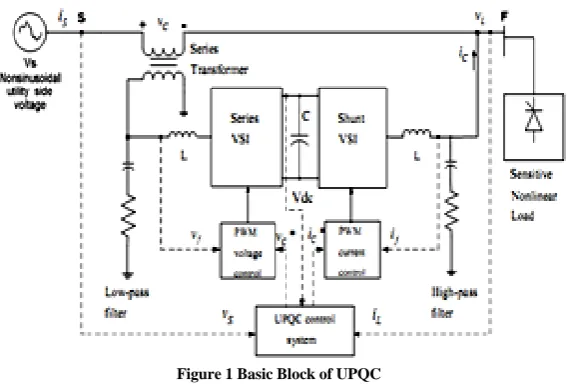
The best protection for sensitive loads from sources with inadequate quality is shunt-series connection i.e. unified power quality conditioner (UPQC). Recent analysis efforts are created towards utilizing unified power quality conditioner (UPQC) to solve nearly all power quality issues for example voltage sag, voltage swell, voltage outage and over correction of power issue and unacceptable levels of harmonics in the current and voltage the fundamental configuration of UPQC is shown in Figure-1.
IJEDR1504005 International Journal of Engineering Development and Research (www.ijedr.org) 2 Figure 1 Basic Block of UPQC
The voltage at PCC could also be or might not be distorted looking on the other non-linear loads connected at PCC. Also, these loads might impose the voltage sag or swell condition throughout their switching ON and/or OFF operation. The UPQC is put in so as to shield a sensitive load from all disturbances. It consists of two voltage source inverters connected back to back, sharing a common dc link. One inverter is connected parallel with the load. It acts as shunt APF, helps in compensating load harmonic current, reactive current and maintain the dc link voltage at constant level. The second inverter is connected in series with the line using series transformers, acts as a controlled voltage source maintaining the load voltage sinusoidal and at desired constant voltage level.
As shown in Figure 1 VS,VC,VL,IC is the supply voltage, series compensation voltage, and load voltage and shunt compensation current respectively. The source voltage may contain negative, zero as well as harmonic component. The system (utility) voltage at pint S can be expressed as:
2 11
(
)
(
)
(
)
k k n
p
S
V
t
V
t
V
t
V
[1]Where V1p is the fundamental frequency positive sequence components, V1n is the fundamental frequency negative sequence components respectively. The last term of equation represents the harmonic content in the voltage and 1p, 1nand kare the corresponding voltage phase angles.
Usually, the voltage at the load of point of common coupling (PCC) is expected to be sinusoidal with fixed amplitude VL:
) sin( 1p L
L V t
V [2]
Hence the series inverter will need to compensate for the following components of voltage:
2 1 11 )sin( ) () ()
( k k n p p L
C V V t V t V t
V [3]
In the subsequent sections, it will be shown how series-APF can be designed to operate as a controlled voltage source whose output voltage would be automatically controlled using the above described logic.
To provide load reactive power demand and compensation of the load harmonic and negative sequence currents, the shunt-APF acts as a controlled current source and its output component should include harmonic and negative sequence components in order to compensate these quantities in the load current. The distorted non-linear load current can be expressed as:
2 1 11 sin( ) () ()
k k n
p p
L I t i t i t
i [4]
It is usually desired to have a certain phase angle (displacement power factor angle),Lbetween the positive sequence voltage and current at the load terminal.
L p p p p L or 1 1 1 1 [5]
Substituting equation [5] into equation [4] and simplifying yields
2 1 1 1 11 sin( )cos cos( )sin () ()
k k n L p p L p p
L I t I t i t i t
i [6]
In order to compensate harmonic current and reactive power demand, the shunt active filter should produce the following current:
2 1 11 cos( )sin () ()
k k n L p p
C I t i t i t
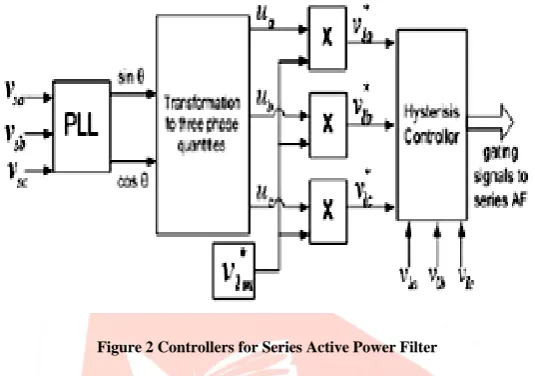
IJEDR1504005 International Journal of Engineering Development and Research (www.ijedr.org) 3 Figure 2 Controllers for Series Active Power Filter
The series filter is controlled such that it injects voltages that wipe out the distortions and/or unbalance present within the provide voltages therefore creating the voltages at the load terminal perfectly balanced and sinusoidal with the specified amplitude. Three phase distorted/unbalanced supply voltages are detected and given to the PLL that generates angle
t varying between 0 and2 radian, synchronized on zero crossings of the fundamental (positive-sequence) of phase A. The detected supply voltage is multiplied with an acceptable value of gain before being given as an input to the PLL. The angle output from the PLL is used to compute the supply in phase, 1200 displaced three unit vectors. The series filter is controlled such that it injectsvoltages
vCa,vCb,vCc
which cancel out the distortions and/or unbalance present in the supply voltages
vSa,vSb,vSc
thus making the voltages at the load terminal
vLa,vLb,vLc
perfectly balanced and sinusoidal with the desired amplitude. The computed three in-phase unit vectors are then multiplied with the desired peak value of the PCC in-phase voltage
vlM which becomes the three-phase reference load voltages as from equation [10].
c b a
Lc Lb La
v
v
v
v
v
v
v
* * *
[10]
To generate injected voltages, supply voltage signals are compared with these reference signals and these signals are then given to the hysteresis controller along with the sensed series APF output voltages.
IV.CONTROLOFSHUNTACTIVEPOWERFILTER
The control process of a shunt active power filter must estimate the current reference waveform for each phase of the inverter, preserve the dc voltage constant, and produce the inverter gating signals. Also the compensation effectiveness of an active power filter depends on its aptitude to follow the reference signal calculated to compensate the distorted load current with a minimum error and time delay. The shunt component of UPQC can be controlled in two ways
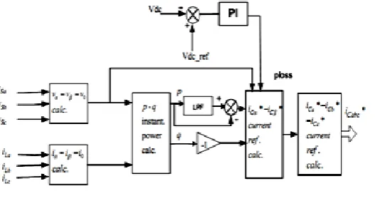
IJEDR1504005 International Journal of Engineering Development and Research (www.ijedr.org) 4 Figure 3 Controller for Shunt Active Power Filer
The concept of instantaneous active and reactive powers and its application for shunt active filter reference currents generation was created by Akagi.
The load current at the point of common coupling is measured and converted to d-q components. The fundamental frequency components when transformed to d-q are filtered out and the harmonic components of current are extracted. The shunt active filter then injects the same magnitude of harmonics but with the opposite polarity so that the harmonic distortions in the source current are cancelled out and remains distortion free. Thus, the source current always remains sinusoidal even if any non-linear load is connected. The value of DC-link voltage depends on voltage level of the point of connection and has to be higher than the peak value of the voltage at the point of connection so that it can compensate for the reactive and harmonic currents of the load. In parallel, the difference between the dc link voltage and its constant reference value is fed to the d axis of current through a PI controller, thus forcing the error to be zero every time the DC voltage deviates from its normal value [9]. The sum of outputs obtained from the filter and the PI regulator is then compared with measured shunt current through a PI controller to obtain the shunt reference current.
The reference current generated is converted to gate signals for the shunt inverter by application of a suitable modulation technique. A hysteresis current controller is used to control the source current as it is an attractive choice because of its simplicity and robustness. The threshold upper limit and lower limit are formed by adding and subtracting appropriate offset values to the input signal. The reference current is now compared with the specified thresholds to generate the switching pulses for the shunt converter.
.
V.SIMULATIONRESULT
The performance of unified power quality conditioner (UPQC) is present in this section to evaluate the proposed control strategy. The simulation models have been developed in MATLAB/SIMULINK environment. The models have been operated for non-linear load as well as unbalanced load. In order to introduce non-linear load a three phase diode bridge with RL load on dc side is used. For unbalanced load we connect three variable resistors as a load. The simulation results under voltage sag and swell condition are presented. Additionally, the simulation result under distorted voltage condition is also presented. The shunt active power filter compensates current disturbances and also maintains the dc link voltage to reference value. While series active power filter compensates voltage related problems for maintaining required load voltage. The whole simulation is run for 0.5 sec. The system parameters used are as follows:
Supply: Voltage and frequency Vs= 400 Vrms, f= 50 Hz,
Load: 3 phase ac line inductance 2 mH
3 phase dc inductance and resistor Ldc3=10mH, Rdc3=30 ohm
DC Link Capacitor C = 6800 μF
Shunt APF: Filter resistor and capacitor: 5 ohm, and 10 μF
Ac line inductance: 3.5 mH
Series APF: Filter resistor and capacitor5 ohm and 20 μF
Ac line inductance: 1.5 mH
IJEDR1504005 International Journal of Engineering Development and Research (www.ijedr.org) 5 0 2000 4000 6000 8000 10000
0 2 4 6 Frequency (Hz) M a g ( % o f F u n d a
0 2000 4000 6000 8000 10000 0 0.5 1 Frequency (Hz) M a g ( % o f F u n d
0 0.1 0.2 0.3 0.4 0.5 -10
0 10
Selected signal: 25 cycles. FFT window (in red): 10 cycles
Time (s)
0 2000 4000 6000 8000 10000 0
5 10
Frequency (Hz)
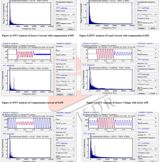
Fundamental (50Hz) = 8.951 , THD= 12.60%
M a g ( % o f F u n d a m e n ta l)
0 0.1 0.2 0.3 0.4 0.5
-5 0 5
x 10-3
Selected signal: 25 cycles. FFT window (in red): 10 cycles
Time (s)
0 2000 4000 6000 8000 10000
0 1 2 3
Frequency (Hz)
Fundamental (50Hz) = 0.00646 , THD= 4.03%
M ag ( % o f F un da m en ta l)
0 0.1 0.2 0.3 0.4 0.5
-100 0 100
Selected signal: 25 cycles. FFT window (in red): 10 cycles
Time (s)
0 2000 4000 6000 8000 10000
0 2 4 6 8 10 Frequency (Hz)
Fundamental (50Hz) = 41.91 , THD= 10.43%
M ag ( % o f F un da m en ta l)
0 0.1 0.2 0.3 0.4 0.5
-100 0 100
Selected signal: 25 cycles. FFT window (in red): 10 cycles
Time (s)
0 2000 4000 6000 8000 10000
0 1 2 3
Frequency (Hz)
Fundamental (50Hz) = 154.6 , THD= 4.36%
M ag ( % o f F un da m en ta l)
Figure 4.1 FFT Analysis of Source Current with compensation SAPF Figure 4.2FFT Analysis of Load Current with compensation SAPF
Figure 4.3 FFT Analysis of Compensation current of SAPF Figure 4.4 FFT Analysis of Source Voltage with Series APF
IJEDR1504005 International Journal of Engineering Development and Research (www.ijedr.org) 6 VI.REFERENCES
[1] Ghosh and G. Ledwich, Power Quality Enhancement using Custom Power Devices, London, Kluwer Academic Publishers, 2002.
[2] Singh, A. Chandra and K. Al-Haddad, “A review of active filters for power quality improvement,” IEEE Trans. Industrial Electronics, Vol. 46, No. 5, pp.960-971, Oct. 1999.
[3] H. Akagi, “New trends in active filters for power conditioning,” IEEE Trans. Industry Applications, Vol. 32, pp.1312-1322, Nov.-Dec.96.
[4] Singh, V. Verma, A. Chandra and K. Al-Haddad, “Hybrid filters for power quality improvement,” IEE Proc. Generation, Transmission and Distribution, Vol.152, pp. 365–378, May 2005.
[5] H. Fujita and H. Akagi, “A practical approach to harmonic compensation in power systems-series connection of passive and active filters,” IEEE Trans. Industry Applications, Vol. 27, No.6, pp.1020-1025, Nov-Dec 1991.
[6] L. Moran, I. Pastorini, J. Dixon and R. Wallace, “Series active power filter compensates current harmonics and voltage unbalance simultaneously,” Proc.IEE Gener., Trans. and Distrib., Vol. 147, No.1, pp.31–36, Jan. 2000.
[7] A. Chandra, B. Singh, B. N. Singh and K. Al-Haddad, “An improved control algorithm of shunt active filter for voltage regulation, harmonic elimination, power-factor correction, and balancing of nonlinear loads,”IEEE Trans. Power Electronics, Vol.15, no.3, pp.495-507, May 2000.
[8] F. Barrero, S. Martinez, F. Yeves, F. Mur, and P.M. Martinez, “Universal and reconfigurable to UPS active power filter for line conditioning,” IEEE Trans. Power Delivery, Vol. 18, No. 1, pp. 283 –290, Jan. 2003.
[9] A Elnady, W. El-Khattam, and M.M.A. Salama, “Mitigation of AC arc furnace voltage flicker using the unified power quality conditioner,” in Proc. IEEE PES Winter Meeting’02, pp. 735-739, 2002.
[10] R. Faranda, R. and I. Valade, “UPQC compensation strategy and design aimed at reducing losses,” in Proc. IEEE-ISIE’02, pp. 1264 -1270, 2002.
[11] S.J. Chiang, W.J. Ai, and F.J. Lin, “Parallel operation of capacity-limited three-phase four-wire active power filters,” IEE Proc. Electric Power Applications, Vol.149, No. 5, pp. 329 –336, Sept. 2002.
[12] S.J. Chiang, “A three-phase four-wire power conditioner with loaddependent voltage regulation for energy saving,” in Proc. IEEE APEC’03, 2003, pp. 159 –164.
[13] Amit Kumar Jindal, Arindam Ghosh and Avinash Joshi, “The protection of sensitive loads from interharmonic currents using shunt/series active filters,” J. Electric Power Syst. Res., Vol. 73, pp. 187-196, Feb. 2005.
[14] M. A. Hannan and A. Mohamed, “PSCAD/EMTDC simulation of unified series-shunt compensator for power quality improvement,” IEEE Trans. Power Delivery, Vol. 20, pp. 1650–1656, Apr. 2005.
[15] S.A.O. da Silva, P.F. Donoso-Garcia, P.C. Cortizo, P.F. Seixas, “A comparative analysis of control algorithms for three-phase line-interactive UPS systems with series-parallel active power-line conditioning using SRF method,” in Proc. IEEE PESC’00, pp. 1023 -1028, 2000.
[16] Zhan, V.K. Ramachandaramurthy, A. Arulampalam, C. Fitzer, M. Barnes and N. Jenkins, “Universal custom power conditioner (UCPC) with integrated control,” in Proc. IEEE PES Winter Meeting’01, pp.1039 -1044, 2001,
[17] H. Fujita and H. Akagi, “The unified power quality conditioner: The integration of series active filters and shunt active filters,” IEEE Trans. Power Electronics, Vol. 13, pp.315-322, Mar. 1998.
[18] A. Elnady, and M.M.A. Salama, “New functionalities of the unified power quality conditioner,” in Proc. IEEE-PES T&D Conf.’01, 2001, pp. 415 -420.
[19] Elnady, and M.M.A. Salama, “New functionalities of an adaptive unified power quality conditioner,” in Proc. IEEE-PES Winter Meeting’01, pp. 295 -300, 2001.