Performance Analysis of Evaporative Cooling System
Vivek Kumar & Mr.Neeraj Saraswat
M.Tech Student (Thermal Engineering) Sunder Deep Engineering College, Ghaziabad, (U.P)
Assistant Professor, Sunder Deep Engineering College, Ghaziabad (U.P)
Abstract-Cooling towers are either used for evaporation of water to get rid of heat and for cooling the operating close to the wet-bulb air temperature or within the loop case.
Dry-Cooling towers rely solely on air to cool the working fluid near the dry-bulb air temperature.
Applications commonly included are Cooling of circulated water utilized by in Oil-Refinery, Chemical-plant, Power-station and Building-cooling. Industrial cooling tower can be utilized for removal heat from many source namely machineries or heating process materials. Large industrial towers primarily used for removal heat from circulated water system in Power-plant system, Food Processing plants, and Semiconductor plants for Industrial facilities.
Keywords:
Cooling tower, F.C.U, Temperature
etc
I .INTRODUCTION
Cooling towers are considered as main part of most of the chemical plants. Cooling tower’s fundamental work is the heat rejection in environment. Water lost by the evaporation is replenished by the make-up source for water. Cooling tower receives hot water from heat exchangers. Water coming out from cooling tower is transferred back again to the exchangers or to different units for more additional cooling.
These design guidelines helps engineers to be understood about fundamental principles for cooling towers. Cooling towers are generally employed for removal extra heat which is developed at different locations i.e. chemical plants, power stations and domestic A.Cs. These equipment has been developed as a relatively less expensive and dependable mode of low grade heat removal from cooling water.
Cooling of the circulated water is utilized by refineries, chemical & petrochemical plants, thermal plants & HAVS systems for building's cooling are Common applications of them.
Fan.coil.unit
A fan.coil.unit (F.C.U.) as an ordinary device consist of either a heating with /or cooling-coil or heat exchanger with a fan. This is applied in buildings used for residence, commercial use, and for industry as the part of a HAVS system. A F.C.U. is a diversified device using sometime duct work and is applied for temp. control at installed/ multiple
areas. It is either controlled by switch for on/off, manually or by thermostatically, used for controlling the through put of the water to the heat-exchanger by using a coil or the fan speed.
The output of a F.C.U. is situated by observing the temp. of the air entering and leaving from the unit i.e. the air volume being passed through the unit. It is the simple statement with more readings there at sensible heat ratio, air's specific heat capacity by which thermal performance is affected.
Cooling Tower
Cooling towers are devices used for heat removal by transferring processed waste heat to the environment. As the concept of evaporation is used by cooling towers so small amount of the water get evaporated into the stream of moving air by subsequent discharge in the environment. Which results the cooling of remaining water significantly.
II. LITERATURE REVIEW
1. Dileep KJ and, Dileep Kumar Baniya, “Design
and Fabrication of Cooling Tower”
2. Vishnu S. Kumar and Reji Mathews, “Performance Analysis and Optimization of Cooling Tower” (2018)-Cooling tower is an integral part of every thermal power generation plant.. Inlet water temperature and mass flow rate of water and air are having main influence on the performance of counter flow induced draft cooling tower. Effectiveness of the cooling tower can be increased up to 20% by optimizing the liquid to gas ratio (L/G) of the cooling tower. Likewise other parameters such as range, tower characteristic ratio can also be increased considerably.
3. Sunil J. Kulkarni and Ajaygiri K. Goswami, “Studies and Experimentation on Cooling Towers: A Review” (2015)- In induced draft cooling towers, air is sucked from other end. The water cooling happens because of humidification of air. The heat lost by water is heat gained by air. Water recirculation is also important aspect in the cooling towers. The effectiveness of cooling tower depends on flow rates of air and water and water temperature. Minimization of heat loss is one of the important aspect of studies carried out by various investigators. The interfacial area between air and water is also crucial factor in cooling towers. Three types of packing used in cooling towers are film, splash and film-grid packing. Also it was observed that drift is one of the important losses in cooling towers. Various shapes of cooling towers are tried by various investigators to study effectiveness. Hyperbolic shape was advantageous due to higher area at bottom. It provides aerodynamics, strength, and stability. The present review is aimed at summarizing studies and research on cooling tower for increasing efficiency and power savings to make it more economical and efficient.
4. Pushkar R. Chitale and Rohan K. Gamare, “Design and Analysis of Cooling Tower” (2018)-. Cooling Tower Works On The Principle Of Evaporative Cooling In Which Water Is Cooled Down By The Impact Of High Velocity Flowing Air. It Offers An Effective Alternative At Locations Where There Is Cooling Water Scarcity And Where Hot Water Discharge Causes An Environmental Concern. The Effective Cooling Of Water Depends On Various Process Parameters Like Dry Bulb And Wet Bulb Temperature Of Air, Fill Material And Its Size, Inlet Air Flow Rate, Air Inlet Angles, Water Flow Rate And Temperature Etc. The Present Paper Is The Detailed Methodology Of Design Of Counter Flow Cooling Tower Based On The Input Process
Parameters By Considering Different Types Of Possible Losses.
III. EXPERIMENTAL SETUP
Evaporative cooling is that process in which warm water coming from the process of an industry is pumped up to the cooling tower's top in which system for distribution of water is employed. Here the cooling tower's nozzles distribute the water to the wet deck and simultaneously air is drawn through the air inlet, louvers that force water to be evaporated. Evaporation is caused the removal of heat from the makeup-water.
Fig : COOLING PROCESS
Fig. COOLING TOWER
There are many components used in the Fan Coil Units. The component used in the fan coil unit are as follows.
1. Fan
2. Coils
3. Motor
4. Shaft.
Fan
Flow within a fluid (mainly in gas such as air) is created by a fan. The fan integrated with a rotating-assembly of vanes / blades which work on the fluid. The rotating blades and hub assembly is called as an impeller-rotor-runner. Generally, it is enclosed by a form of housing /case. Which may direct the air-flow or increasing safety by preventing contact of objects with the fan blades. Mostly electrically operated motors are employed with fans but another sources (including I.C. engines) may also be used for power,
High-volume and low-pressure flow is developed by fans (mainly more than ambient pressure), opposed by compressor that produce high-pressure at a relatively low-volume. Wind turbine with designs similar to a fan rotate a fan blades exposing to a fluid stream.
Complex applications included, climate-control and personal-thermal-comfort (e.g., as an electric-table /floorfan), engine-cooling system of vehicles(e.g., radiator front), machine-cooling-systems (e.g., inbuilt-computer and audio-power-amplifier), ventilations, fume extractor, (e.g., separating-chaff for cereals and grain), dust removal (e.g. as vacuum cleaner), drying (generally with combined by a heating-source) and fire-draft provider.
Generally fans utilized for cooling people and not really for cooling air (anyway an electric.fan warms it slightly due to the warming of its motor) but in case of evaporating- cooling- sweat that increase convection of heat in atmospheric air due to the air-flow from the fans and therefore fans may be in-effective for body-cooling if the surrounded-air is at near the body temp. and containing high-humidity. At the time of very high heat and humidity, it is really advised not to use fans.
Coils
The core to an A.C. system is a refrigerant.gas which goes through gaseous.state to liquid.state by the process of compressing and again then changing into gaseous state by the absorption of available heat in the room. It going through a refrigeration-process that is divided into four main parts:
1. Compression: The gas is converted into a high.pressure, hot.liquid when pressurized.
2. Condensation: High-pressure, hot-liquid-refrigerant is converted in cool-liquid by releasing heat into the outside.air after flowing through a coil e. It is the part using coils.
3. Expansion-valve: High-pressure liquid is converted into low-pressure liquid by a valve.
4. Evaporation: An evaporating coil again receives this low-pressure liquid, where heat is absorbed from the room and it converts from liquid to gas. In case of split A.Cs this process takes place in the in-door unit while all other processes in the out-door unit.
Principally the heat is transferred from the inside.air to outside.air and this heat-transfer take place in the coils.
The refrigerant evaporates (changes into gas from liquid) in the evaporation-coils by absorbing the heat from the air (inside the room) by passing-over it. The air (inside the room) cooled by this process and directed into the room. The gaseous.refrigerant then goes through the compression and then condensation in coils where it condenses by released heat into the air surrounding it. Exhaust fans blow out the warm air.
This working-principle for all types of H.V.A.C. systems remains same only the size of the system keeps changing. Thus the efficiency of H.V.A.C. systems is affected by the type of coils used, the.size of the coil, the material used for making, cleaning and maintenance ease etc. All play an important role in the functioning of a H.V.A.C. systems.
.IV. EXPERIMENTAL CALCULATION AND RESULT COOLING.TOWER APPROACH
The difference between the Coldwater temp. (Outlet of Cooling tower) and Ambient wet-bulb-temp. is called as Cooling-tower-approach.
Approach = Cold-water temperature – Wet-bulb temperature
Approach is the good indicator for its performance.
COOLING-TOWER RANGE
The difference between the Hot-water temperature (Inlet of Cooling-Tower) and Cold-water temperature (Outlet of Cooling-Tower) is called Cooling-tower-range. Range = Hotwater temp. – Coldwater temp.
Hot water temperature: 31.8 degree Celsius
Wet bulb temperature: 25 degree Celsius
Cooling Tower Efficiency = (31.8 – 26.8) x 100/ (31.8 – 25)
=73.5%
Cooling tower efficiency=0.735
RATE OF HEAT TRANSFER BY F.C.U.
Q =m*C*dt.
m = mass flow rate
C = specific heat of water.
dt = change in temperature.
Q = 0.305*4185.5*(25.8-25)
Q = 1021.14 JOULE
POWER CONSUMPTION
BLOWER MOTOR=75 WATT (930rpm)
SUMP MOTOR=18WATT =18 WATT
EXHAUST FAN MOTOR= 160 WATT (2300 rpm)
UNIT= WATT* hour/1000
= (75+18+160) *24 / 1000
=6.072 unit
SELECTION OF AIR CONDITIONER
TON =3√volume of room / 10
Volume of room = (height *width* length)
=10*10*10
=1000
Ton = 3√1000/10
=1 ton
COOLING TOWER SUMP WATER CAPACITY
DIMENSIONS :
Length= 470 mm,
Width=460 mm,
Height = 178 mm.
VOLUME =l*b*h
= 470*460*78
=16863600 mm3.
=16.86 liters
Pump water flow rate = 1100L /hr. =18.33L/ min.
=0.305 L /sec.
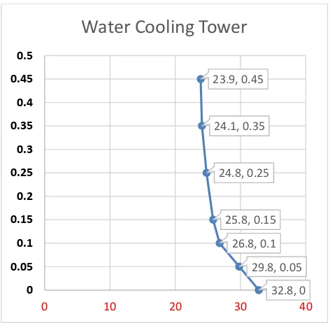
Fig. Water temp. V/s Time, at Room temp. 30.8
32.8, 0 29.8, 0.05 26.8, 0.1 25.8, 0.15 24.8, 0.25 24.1, 0.35 23.9, 0.45
0 0.05 0.1 0.15 0.2 0.25 0.3 0.35 0.4 0.45 0.5
0 10 20 30 40
Fig. Inlet Wt. & Outlet Wt. v/s Time
REFERENCES
[1]. R. Ram Kumar A. Ragupathy, Thermal Performance of Forced Draft Counter Flow Wet Cooling Tower with Expanded Wire MeshPackingInternational Journal on “Technical and Physical Problems of Engineering” (IJTPE), Issue. 6, Vol. 3, No. 1, Mar. 2011.
[2]. Bhupesh Kumar Yadav, S. L. Soni, Experimental Study of the Performance of Cooling Tower ISSN: 2249 – 8958, Volume-4 Issue-2, December 2014
[3]. Xiaoni Qi, Yongqi Liu, Zhenyan Liu, Exergy Based Performance Analysis of a Shower Cooling Tower - Journal of Mechanical Engineering 59(2013)4, 251-259.
[4]. Ronak Shah, TruptiRathod, Thermal Design Of Cooling Tower, International Journal of Advanced Engineering Research and StudiesE-ISSN2249–8974.
[5]. Pushpa B. S, VasantVaze, P. T. Nimbalkar Performance Evaluation of Cooling Tower in Thermal Power Plant - A Case Study of RTPS, Karnataka International Journal of Engineering and Advanced Technology (IJEAT), International Journal of Engineering and Advanced Technology (IJEAT) ISSN: 2249 – 8958, Volume-4 Issue-2, December 2014.
[6]. UpasnaSethi, ManishaKumari, and Dharini Shah “A Review in Design and Performance Analysis of Cooling Tower “e-ISSN: 2395 -0056 Volume: 03 Issue: 12 | Dec -2016 p-ISSN: 2395-0072.
22 22.5 23.1 23 23.1 22.9 22.2
24.5 25.1 25.8 26.2 25.9
26.7 28.4
0 0.05 0.1 0.15 0.2 0.25 0.3
0 5 10 15 20 25 30
1 2 3 4 5 6 7