Available Online atwww.ijcsmc.com
International Journal of Computer Science and Mobile Computing
A Monthly Journal of Computer Science and Information Technology
ISSN 2320–088X
IMPACT FACTOR: 6.017
IJCSMC, Vol. 6, Issue. 5, May 2017, pg.202 – 208
Review on Seismic Analysis of
Elevated Water Tank with Variations
of H/D Ratio and Container Shape
Mayank Gopal Manwani
1, Deepa P. Telang
2¹Dept. of Civil Engg & G.H. Raisoni Academy of Engineering & Technology, Nagpur (MS), India
²Dept. of Civil Engg & G.H. Raisoni Academy of Engineering & Technology, Nagpur (MS), India
1
[email protected]; 2 [email protected]
Abstract— As known from very upsetting experiences, liquid storage tanks were collapsed or heavily damaged
during the earthquakes all over the word. The economic lifetime of concrete or steel tanks is usually in the range of 40 to 75 years (ALA 2001).Damage or collapse of the tanks causes some unwanted events such as shortage of drinking and utilizing water, uncontrolled fires and spillage of dangerous fluids. Due to this reason numerous studies done for dynamic behavior of fluid containers; most of them are concerned with cylindrical tanks. In this study, Seismic forces acting on an Elevated water tank e.g. circular Tank and rectangular tank are studied with constant stagging height. Seismic forces acting on the tank are also calculated changing the Seismic Response Reduction Factor(R). IS: 1893-1984/2002 for seismic design and then checked the Design of Tanks by using the software STAAD PRO.
Keywords:- water tank, stagging system, staad pro, earthquake.
1. INTRODUCTION
membranes to prevent leakage. Reservoir is a common term applied to liquid storage structure and it can be below or above the ground level. Reservoirs below the ground level are normally built to store large quantities of water whereas those of overhead type are built for direct distribution by gravity flow and are usually of smaller capacity.
Elevated tanks should remain functional in the post-earthquake period to ensure water supply is available in earthquake-affected regions. Never the less, several elevated tanks were damaged or collapsed during past earthquakes Due to the fluid–structure–soil/foundation interactions, the seismic behavior of elevated tanks has the characteristics of complex phenomena. Therefore, the seismic behavior of elevated tanks should be known and understood, and they should be designed to be earthquake-resistant. Some general programs have been carried out, which cover large amounts of data; these programs include STAAD PRO etc.
However, a general-purpose structural analysis program generally exists in every engineering office. So, the evaluation of the applicability of these structural analysis programs in the design of elevated tanks is important from an engineering point of view and it will be helpful to present the application and results to designers. There is a second important reason that should be considered. That is, simplified models are used for a straightforward estimate of the seismic hazard of existing elevated tanks. Only if the estimated risk is high, it is convenient to measure all the data (e.g. geometry of the tank, material properties) that are required by the general finite element codes and to spend time and money to prepare a reliable general model.
A. Earthquakes:
An Earthquake is a phenomenon that results from and is powered by the sudden release of stored energy in the crust that propagates Seismic waves. At the Earth's surface, earthquakes may manifest themselves by a shaking or displacement of the ground and sometimes tsunamis, which may lead to loss of life and destruction of property. The word Earthquake is used to describe any seismic event whether a natural phenomenon or an event caused by humans—that generates seismic waves. Most naturally occurring earthquakes are related to the tectonic nature of the earth. Such earthquakes are called tectonic earthquakes. The Earth's lithosphere is a patchwork of plates in slow but constant motion caused by the heat in the Earth's mantle and core. Plate boundaries grind past each other, creating frictional stress. When the frictional stress exceeds a critical value, called local strength, a sudden failure occurs. The boundary of tectonic plates along which failure occurs is called the fault plane. When the failure at the fault plane results in a violent displacement of the Earth's crust, the elastic strain energy is released and seismic waves are radiated, thus causing an earthquake. Earthquakes occurring at boundaries of tectonic plates are called inter plate earthquakes, while the less frequent events that occur in the interior of the lithosphere plates are called inter plate earthquakes. The severity of an earthquake can be measured in terms of magnitude and intensity. For that seismologists use two fundamentally different but equally important types of scales. The original force or energy of an earthquake is measured on a magnitude scale. The Richter scale is a well-known example of a magnitude scale. The second type of scale measures the intensity of shaking occurring at any given point on the Earth's surface. These scales are referred to as intensity scales. The Mercalli intensity scale, which measures the effects of the seismic waves, is an example of a commonly used intensity scale. The non-specialized media will often refer to the magnitudes of earthquakes as being reported on the Richter scale. However, the magnitudes reported nowadays are actually on the moment magnitude scale.
B. Water Tanks:
In general there are three kind s of water tanks-tanks resting on ground, underground tanks and elevated tanks. The tanks resting on ground like clear water reservoirs, settling tanks, are ration tanks etc. are supported on the ground directly. The walls of these tanks are subjected to pressure and the base is subjected to weight of water and pressure of soil. The tanks may be covered on top. The tanks like purification tanks, Imhoff tanks, septic tanks, and gas holders are built underground. The walls of these tanks are subjected to water pressure from inside and the earth pressure from outside. The base is subjected to weight of water and soil pressure. These tanks may be covered at the top. Elevated tanks are supported on staging which may consist of masonry walls, R.C.C. tower or R.C.C. columns braced together. The walls are subjected to water pressure. The base has to carry the load of water and tank load. The staging has to carry load of water and tank. The staging is also designed for wind forces. From design point of view the tanks may be classified as per their shape- rectangular tanks, circular tanks, intze type tanks. Spherical tanks conical bottom tanks and suspended bottom tanks.
mix shall be such that the resultant concrete is sufficiently impervious. Efficient compaction preferably by vibration is essential. The permeability of the thoroughly compacted concrete is dependent on water cement ratio. Increase in water cement ratio increases permeability, while concrete with low water cement ratio is difficult to compact. Other causes of leakage in concrete are defects such as segregation and honey combing. All joints should be made water-tight as these are potential sources of leakage. Design of liquid retaining structures is different from ordinary R.C.C, structures as it requires that concrete should not crack and hence tensile stresses in concrete should be within permissible limits.
2. LITERATURE REVIEW
For same capacity, same geometry, same height, with same staging system, in the same Zone, with same Importance Factor & response reduction factor; response by Equivalent Static Method to Dynamic method differ considerably. It also state that even if we consider two cases for same capacity of tank, change in geometric features of a container can show the considerable change in the response of elevated water tank. At the same time Static response shows high scale values that of the Dynamic response. It happens due to the different picks of time periods. For Static analysis water- structure interaction shows that both water and structure achieve a pick at the same time due to the assumption that water is stuck to the container and acts as a structure itself and both structure and water has same stiffness, while in Dynamic analysis we considered two mass model which shows two different stiffness for both water and structure hence pick of time for both the components are different hence fundamental time periods are different for both static and dynamic analysis. But secondary time period in dynamic analysis is greater than both fundamental time periods because water in the upper region (Convective region) remains in un damped condition (sloshing condition) for some more time.
Column moment in bracing increases by increasing height of staging of water tank. Column moment is minimum for radial bracing. Shear force in bracing increases by increasing height of staging. Shear force in bracing is minimum for radial bracing. Comparison of base shear value by manual and software method is in permissible limit that is 1.17% less value in software analysis as compare to manual. Axial column force and base shear is not much affected by height of staging. Bending moment in bracing increases by increasing height of staging. Maximum displacement increases by increasing staging height for zone IV. Cross bracing gives minimum value for base shear for all zone and staging height. Maximum displacement value is minimum for radial bracing. Maximum displacement is greater in cross bracing. Overturning moment is minimum for cross bracing. By considering results of analysis radial bracing performs better in all manner as compared to cross bracing and normal bracing.
Seismic analysis and performance of elevated RC circular water tank have been presented in this study for frame type of staging pattern. Generally, when earthquake occur major failures of elevated water tank take place due to failure of supporting systems, as they are to take care for seismic forces. Therefore supporting structures of elevated water tanks are extremely vulnerable under lateral forces due to an earthquake. Modeling and static analysis is performed using STAAD PRO software. Further, the behavior of elevated water tank with staging pattern is analyzed using two mass model methods. Seismic analysis of overhead circular water tank carried out in accordance with IS: 1893- 1984 and IS: 1893-2002 (Part-2) draft code. The analysis is carried out for elevated circular tank of 1000 Culm capacity, located in four seismic zones (Zone-II, Zone -III, Zone-IV, Zone-V) and on three different soil types (Hard rock, Medium soil, Soft soil). Further, three different tank-fill conditions - tank full, tank 50% full, tank empty are also considered in this study. The seismic responses of circular tanks are computed and compared based on the theoretical procedures of IS: 1893-1984 and IS: 1893-2002(Part-2) draft code. The analysis was performed using SAP-2000 software package also. The parameters of comparison include base shears, base moments, impulsive and convective hydrodynamic pressures on tank wall and base slab. The results of the analysis showed an increase in base shear, base moment, hydrodynamic pressure and time period with increasing zone factor for all soil types and tank fill conditions considered.
IS:1893- 2002 (Part -2) draft code Provisions, base shear increased by 56%, 135% and 253% with zone changing from II to III, IV and V respectively in hard rock. The corresponding values are 56%, 135% and 253% and 54%, 131% & 246% respectively for medium and soft soil with tank full condition. The base shear values have been 60%, 140% & 260% and 54%, 131% & 246% for tank 50% full and tank empty conditions in hard rock, medium soil and soft soil respectively.
3. SEISMIC ANALYSIS OF ELEVATED WATER TANK
Seismic analysis of elevated water tank involved two types of analysis,
1. Equivalent Static analysis of elevated water tanks.
2. Dynamic analysis of elevated water tanks
Equivalent static analysis of elevated water tanks is the conventional analysis based on the conversion of seismic load in equivalent static load. IS: 1893- 2002 has provided the method of analysis of elevated water tank for seismic loading. Historically, seismic loads were taken as equivalent static accelerations which were modified by various factors, depending on the location’s seismicity, its soil properties, the natural frequency of the structure, and its intended use. Elevated water tank can be analyzed for both the condition i.e. tank full condition and tank empty condition. For both the condition, the tank can be idealized by one- mass structure. For equivalent static analysis, water-structure interaction shows, both water and structure achieve a pick at the same time due to the assumption that water is stuck to the container and acts as a structure itself and both water and structure has same stiffness. The response of elevated water tanks obtained from static analysis shows the high scale value. That’s why for large capacities of tanks, static response are not precise. If we analyzed the elevated water tank by static method and design by the same, we get over stabilized or say over reinforced section but it will be uneconomical. That’s why static systems of designing of elevated water tanks is not useful in seismic zones. And hence, IS code provision for static analysis is restricted for small capacities of tanks only.
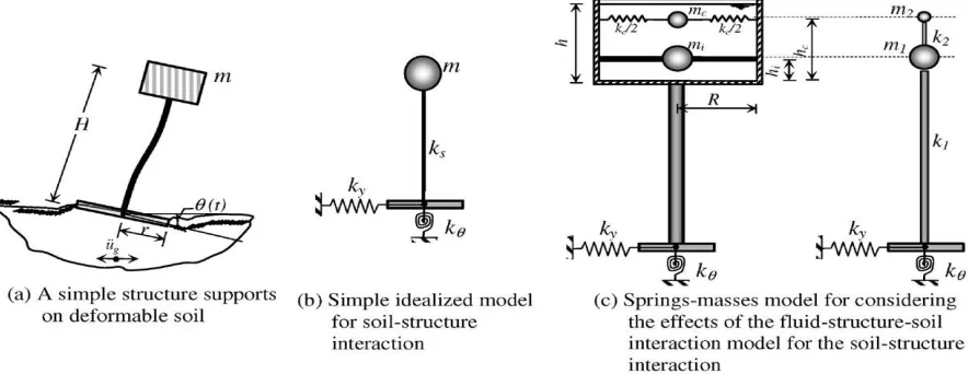
Fig. 1. Mechanical model for the fluid–structure–soil interaction of the elevated tank
A. Single lumped-mass model
all the supporting structure types. But it may be that these are more suitable for the reinforced concrete shell supporting structure.
The Indian seismic code, IS:1893, requires elevated tanks to be analyzed as a single-degree-of-freedom system— that is, a one-mass system—which suggests that all fluid mass participates in the impulsive mode of vibration and moves with the container wall (Rai, 2002). It must be stated that this can be a realistic assumption for long and slender tank containers with a height-to-radius ratio exceeding four. Also, the ACI 371R-98 (1995) suggests that the single lumped mass model should be used when the water load (Ww) is 80% or more of the total gravity load (WG) that includes: the total dead load above the base, water load and a minimum of 25% of the floor live load in areas that are used for storage. For this model, the lateral flexural stiffness of the supporting structure (ks) is determined by the deflection of the concrete supporting structure acting as a cantilever beam.
Fig. 2 Elevated tanks and the single lumped-mass model: (a) the tank with reinforced concrete shaft supporting structure, (b) the tank with reinforced concrete frame supporting structure, (c) the tank with reinforced concrete frame with diagonal braces or steel frame supporting structure, (d) the tank with masonry pedestal supporting structure, (e) single lumped-mass model.
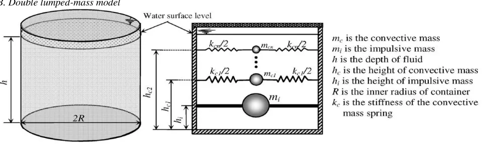
B. Double lumped-mass model
Fig.3 Spring-mass analogy for ground supported cylindrical tanks.
Most elevated tanks are never completely filled with liquid. Hence a two-mass idealization of the tank is more appropriate as compared to a one mass idealization, which was used in IS 1893: 1984. Two mass model for elevated tank was proposed by Housner (1963) and is being commonly used in most of the international codes.
4. METHODOLOGY
considered for analysis. It is analyzed for four different zones (zone-II to V), and for two tank-fill conditions, i.e. tank full and tank empty conditions. Lastly, the results of the analysis of tanks performed on the basis of IS: 1893-1984 and IS: 1893-2002 (Part 2) draft code have been compared by using the software STAAD PRO software.
Step 1: Open STAAD.Pro and click on new project again click on space give file name and location, click on next add beam complete the task with proper directions.
Step 2: Now click on transalatinal circular repeat option make total no of steps =10 then click on link steps open base will apper select one refernce point axis of roatation Y and click on ok.
Step 3: Assigning Properties: click on property then property dialog box will opens and click on define rectangle, give the property of column and click on add close now select all the columns, assign to selected beams make a proper completion assign yes.
Step 4: Go to define and rectangle finally give the property of lower beams and click on add close and select lower beams for assign to selected beams.
Step 5: Go to define and select rectangle shape give the property of lower ring beam and click on add close to select lower beam assign to selected beams and assign.
Step 6: Go to define and rectangle arrangement give the property of upper ring beam and click on add close to select upper ring beam and assign to selected beams and assign.
Step 7: Go to define and thickness to give the property of plates and click on add close the select plates and assign to selected plates and assign.
Step 8:
details add give load or self weight to water tank assign to view assign yes.
Step 9: Go to load case details Add seismic load items dialog box will opens click on seismic load select type 1 Go to load case details add live load give name as hydrostatic load click on hydrostatic load items dialog box will opens click on plate loads select trapezoidal plate load direction of pressure Global Z Variation along element Y Give intensity as per height of the water tank multiplied by unit weight of water select required plates for hydrostatic force Assigned to selected plates Assign yes select lower plates of water tank give intensity according to its height assign hydrostatic load on lower portion of water tank.
Step 10: Go to load case details click on auto load combination select load combination type-Indian select load combination category –general structures click on generate loads add now go to analyze Run analysis go to post processing mode for required results. The same procedure will be followed to create models for different seismic loads.
5. CONCLUSION
Following are the conclusions based on the Seismic Analysis of Elevated Water Tank are as follows:
1. Base shear of full water tank and empty water tank are increased with seismic zone II-V because of zone factor, response reduction factor etc. while considering seismic analysis.
2. Base shear in full condition tank is slightly higher than empty tank due to absence of water or hydro static pressure.
3. Displacement of full water tank and empty water tank are increased with seismic zone II-V because of zone factor, response reduction factor etc. while considering seismic analysis.
4. Maximum nodal displacement and minimum nodal displacement found at the wall of water tank when tank is full condition.
5. Shear force and bending moment of full water tank and empty water tank are increased with seismic zone II-V because of zone factor, response reduction factor etc. while considering seismic analysis.
REFERENCES
[1]. Jain Sudhir K., Sameer U.S., 1990, ―Seismic Design of Frame Staging For Elevated Water Tank‖ Ninth Symposium on Earthquake Engineering (9SEE-90), Roorkey, December 14-16, Vol-1.
[2]. Sudhir K.Jain & O.R.Jaiswal, September-2005, Journal of Structural Engineering Vol-32, No.03. [3]. Ranjit Singh Lodhi & Dr.Vivek Garg., (2014). ―Design of Intze Tank in Perspective of Revision of IS: 3370, Vol.-03 Issue No.9, pp: 1193-1197.
[4]. Luis A. Godoy, ―Damage Due to Buckling in Above Ground Storage Tank‖, University of Puerto Rico, Mayaguez, PR 00681-9041, Puerto Rico.
[5]. Irwin P, Kilpatrick J and Frisque A (2008) ―Friend or Foe, Wind Height‖. CTBHU 8th World Congress Aatish Kumar., R.K.Pandey., 2013, ―Wind Effects on Overhead Tank under Different Soil Parameters‖ IJEAT Vol.-2, No.-6.
[6]. I.S 1893 (Part I) -1984, ―Criteria for Earthquake Resistant Design of Structures‖.
[7]. IS: 3370 (Part I-II) -2009, General Requirements, Code of Practice for Concrete Structures for the Storage of liquids.
[8]. IS: 3370 (Part IV) -1967, Design Tables, Code of Practice for Concrete Structures for the Storage of liquids.
[9]. IS: 875 (2002) ―Code of Practice for Design Load‖ Bureau of Indian Standard, New Delhi.
[10]. IS: 456 (2000) ―Plain and Reinforced Concrete- Code for Practice‖ Bureau of Indian Standard, New Delhi.
[11]. STAAD Pro. 2007, Structural Analysis and Design programming-2007 for analysis of lateral stiffness. [12]. Sushil Kumar., (2014), ―Treasure of RCC Design Vol-IX‖, Rajsons Publication Pvt. Ltd., New Delhi, India.