1
A COMPUTER PROGRAMMED DESIGN
OPTIMISATION AND ANALYSIS OF
COMPRESSOR IMPELLER
G. Naga Malleshwar Rao
1, Dr. S.L.V. Prasad
2, Dr. S. Sudhakarbabu
31, 2 – Professor of Mechanical Engineering, Shri Shirdi Sai Institute of Science and Engineering, Anantapuramu
3-Professor of Mechanical Engineering, AVR&SVR College of Engineering & Technology, Kurnool E-Mail id: [email protected], [email protected]
ABSTRACT
Centrifugal compressors are most widely used in large capacity refrigeration and air conditioning plants. Its other applications include in gas turbines for air craft applications, diesel engine turbochargers, chemical and process industries, factory workshop air supplies etc. In refrigeration field these are suitable for high specific volume refrigerants or low pressure stages. They have been used commonly for R-11, R-12, R-113, R-500, R-717 and eco-friendly refrigerant R-134a. As it is a high speed rotary machine, a large volume can be handled by it and therefore, found extremely suitable for large capacity installations.
The centrifugal compressor stage consisting of an impeller, a vaneless space and/or a vane diffuser is significantly influenced by the performance of impeller. Real flow is three dimensional, viscous, in stationary and more complex to analyze. Scope of the present work is to design an impeller of a centrifugal compressor used for a 400 ton capacity air-conditioning plant. Dimensions of the impeller are estimated by developing a computer code based on the jet-wake theory. Pressure ratio and mass flow rate of the refrigerants are arrived from the thermodynamic cycle analysis and these are taken as inputs to estimate the impeller geometry. The vapor compression cycle calculations are performed for different refrigerants such as R-12, R-500, R-134a and R-152a. An impeller for a 3.4 pressure ratio centrifugal compressor is designed with R-12. The methodology is suitable for an impeller for any other application. The present method is validated from geometry available in the literature. Predicted results are very encouraging when compared with the existing design.
Key Words: Centrifugal compressors, eco-friendly refrigerant, vane diffuser, Jet-wake theory.
1. INTRODUCTION
The use of centrifugal compressor for refrigeration applications was made by Dr. Willis Carrier in 1920 [3]. As it is a high speed rotary machine, a large volume can be handled by it. It is, therefore, found extremely suitable for large capacity application. Centrifugal compressors require high tip speeds to develop the necessary pressure ratio. The high tip speed is achieved by employing either a large diameter impeller or high rpm or both. Because of large peripheral speeds, the velocities in general including the flow velocity are high. Also, there must be a reasonable width of the shrouds to minimize friction and achieve high efficiency. Thus, because of the sufficiently large flow area and large flow velocity, the minimum volume that can be handled by a centrifugal compressor is about 50 cubic meters per minute. A single centrifugal compressor, therefore, can be designed for a minimum capacity approximately of 250 TR with R 11 and 150 TR with R 113 for the purpose of air conditioning. The centrifugal compressors are, therefore, used in large capacity installations in which the load varies through a wide range [2].
2 been used commonly for R-11, R-12, R-113, R-500 and R-717. The hermetic centrifugal compressors are also manufactured up to 4600 ton capacity. The common speed of the hermetic centrifugal compressor is about 3600 rpm, though in some cases it may go as high as 18,000 rpm [6].
The centrifugal compressor consists of an impeller, a vaneless diffuser and/or a vaned diffuser and a volute casing. Impeller imparts a stagnation enthalpy input to the air by increasing its angular momentum. This stagnation enthalpy rise consists of both a static enthalpy rise and a dynamic head rise. The vaneless diffuser reduces the velocity of supersonic flow to subsonic condition without shock losses provided the radial velocity component is subsonic. The radius ratio will be chosen so that the inlet flow to the vaned diffuser (if present) will be subsonic. Design of vane less diffuser is very important to avoid shock waves and stabilize the flow before the flow entries to vaned diffuser. In the vane less space diffusion takes place in the increasing diameter annulus bounded by two radial walls. The most important geometric parameter in the vane less diffuser is the radius ratio.
2. AIM AND OBJECTIVES OF THE PRESENT WORK
The main aim of the present work is to develop a methodology for the design of a centrifugal compressor consists of an impeller and a vaneless diffuser.
The objectives of the project work are as follows:
To understand the flow physics of centrifugal compressor impeller taking into account the real flow phenomena like compressibility effects, development of boundary layer, flow separation, mixing, friction, secondary losses, blockage etc. and their effect on the performance.
To study the various methods to design impeller of a centrifugal compressor
To develop a methodology for design of centrifugal compressor taking into all possible losses to simulate the real flow phenomena as accurate as possible.
To evaluate detailed analysis of the impeller at design point.
To compare the results of theoretical model with the available actual design geometry for the purpose of validation of the method.
3. DETAILS OF A CENTRIFUGAL COMPRESSSOR
3.1. Description
The compression process is carried out in a centrifugal compressor, which comprises mainly of the following elements (Figure 1)
Figure 1. Centrifugal compressor
1) The inlet casing with converging nozzle: Whose function is to accelerate the fluid to the impeller inlet. The
outlet of the inlet casing is known as the eye.
2) The impeller: In which the energy transfer takes place, resulting in a rise of fluid kinetic energy and static
3 3) The diffuser: Whose function is to transform the high kinetic energy of the fluid at the impeller outlet into
static pressure.
4) The outlet casing: This comprises a fluid collector known as a volute or scroll.
3.2. Design optimization and analysis
A computer program is developed based on the methodology discussed in Chapter-3. The method is first validated by taking known centrifugal compressor impeller geometry from the literature.
3.3. Validation of the method
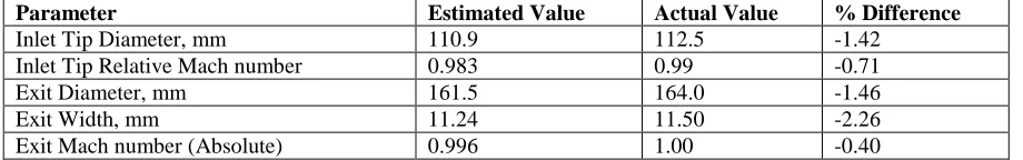
The method is validated by applying it to a centrifugal compressor impeller whose geometry is available in the literature. Results are very encouraging when compared with the actual dimensions (Table 1).
Details of a centrifugal compressor of 3.5 pressure ratio with a mass flow rate of 1.2 kg/s rotating at 50500 rpm is taken to validate the methodology.
Inlet Conditions: Other Geometry Details:
Entry Temperature = 288.15 K Hub Diameter = 50.0 mm Entry Pressure = 101.325 kPa No, of Vanes = 16 Blade Shape = Radial
Table – 1: Comparison of Estimated Design Values and Actual Design Value
Parameter Estimated Value Actual Value % Difference
Inlet Tip Diameter, mm 110.9 112.5 -1.42
Inlet Tip Relative Mach number 0.983 0.99 -0.71
Exit Diameter, mm 161.5 164.0 -1.46
Exit Width, mm 11.24 11.50 -2.26
Exit Mach number (Absolute) 0.996 1.00 -0.40
3.4. Application of the method
After gaining the confidence by validating the design optimization methodology, the same is applied to the refrigerant compressor. Selection of Speed and Refrigerant are iteratively solved. Results of a typical run with R-12 as refrigerant is given below. Speed is selected based on the various design parameters as per the Table 1. The effect of speed on different design parameters are given in Table 2.
As the rotational speed increases Inlet relative Mach number increases. Without using IGVs (Inlet Guide Vanes), centrifugal compressors can be designed up to a maximum Inlet tip relative Mach number of 1.2. Specific speed is also another important factor in the design of centrifugal compressor. Optimum specific speed in FPS units from Balje’s diagram is around 100.
Fig2. Variation of Inlet tip relative Mach number and Exit Mach number
4 design and which should not exceed 1.2 in the absence of pre-whirl vanes. According to this 19000 rpm is suitable because corresponding Mach number is 1.184. But a speed of 18000 rpm is selected with a corresponding Mach number of 1.132 for a safe design as theoretical values are normally slightly lesser side as compared to the actual values. Absolute Mach number at the exit of impeller decreases as the speed increases for a given conditions such as entry temperature and pressure, mass flow rate and pressure ratio. Corresponding to 18000 rpm the exit absolute Mach number is 0.99.
40
Fig3. Variation of Balje’s Specific speed Fig4. Variation of exit diameter with respect to rotational speed
Fig.3 shows the variation of Balje’s Specific speed (in FPS units) with respect to rotational speed ranging 10000 rpm to 20000 rpm. As the speed increases the specific speed also increases for a given mass flow rate. At 18000 rpm the specific speed is around 96 which is near to the maximum value.
Fig.4. depicts the variation of exit diameter with respect to rotational speed ranging 10000 rpm to 20000 rpm. As the speed increases the exit diameter D2 decreases for a given mass flow rate and pressure ratio. Exit
diameter is 202.9 mm corresponding to the speed of 18000 rpm.
70
Fig5. Variation of axial length with respect to rotational speed
5
Table - 2 The effect of speed on design parameters of compressor (for R-12)
4. CONCLUSIONS
A method for preliminary design and analysis of a centrifugal compressor impeller suitable for digitization has been evolved with emphasis placed on the practical design approach.
Real flow effects of Reynolds’s number, flow separation, losses due to friction, clearance or leakage losses, mixing losses etc. are taken into account in the design optimization process and analysis of centrifugal impeller.
Predicted results are very encouraging when compared with existing design data.
Continuation of this work involves the development of a method to generate blade coordinated for the resulted geometry and 3D modeling of the impeller.
This can be further refined in succeeding levels of design process through 2D and/or 3D aerodynamic, stress and CFD Analysis.
This method is suitable for the impeller design and analysis of any application such as in turbocharger applications, small air craft engines, and process industries.
References
[1] Ramamurthy S, Sankaranarayanan S and Murugesan K, Aerodynamic Design of High Pressure Ratio Centrifugal Compressors, NAL-TM PR 8602, March 1986.
[2] C. P. Arora, Refrigeration and Air Conditioning, Eighth Reprint, Tata McGraw-Hill Publishing Company Limited, 1990. [3] S.C. Arora and S. Domkundwar, A course in Refrigeration and Air Conditioning (environmental Engineering), 4th Edition,
Dhanpat Rai and Sons, 1994.
[4] David Japikse, Centrifugal Compressor Design and Performance, Concepts ETI, Inc.,Wilder, VT, 1996.
[5] David Japikse, Nicholas C Baines, Introduction to Turbomachinery, Concepts ETI, Inc., Norwich, VT and Oxford University Press, England, 1997.
[6] Manohar Prasad, Refrigeration and Air Conditioning, New Age International Publishers, 1999.
[7] Saravanamutto H I H, Rogers G F C and Cohen H, Gas Turbine Theory, Pearson Education Pte. Ltd., 2003. [8] Klaus H Ludtke: Process Centrifugal Compressors, Springer-Verlag Berlin Heidelberg, New York, 2004.
[9] Giridhar Kumar D ,Performance Prediction of Centrifugal Compressor and its Matching for other Gas Turbine Components to evaluate Aero-engine Performance, Ph.D Thesis submitted to the Jawaharlal Nehru Technological University, Hyderabad, October 2006.
Speed (rpm)
Design Parameter Unit 10000 12000 14000 16000 18000 19000 20000
Inlet Tip Relative Mach Number 0.705 0.815 0.922 1.028 1.132 1.184 1.236
Exit Diameter mm 405.9 338.2 289.9 253.7 225.5 213.6 202.9
Absolute mach Number at Exit 1.055 1.046 1.029 1.010 0.990 0.980 0.960
Axial Length mm 116.80 103.54 93.93 86.66 80.97 78.56 76.38