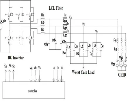
359
Design of Controller for Grid-Connected and Intentional
Islanding Operations of Distributed Power Generation
Mr. C.D.Kulkarni
1, Mrs. S.N.Chaphekar
2 A.P.Electrical Engineering1, 2AISSMS COE Pune1 PES Modern COE Pune2
Abstract: Intentional islanding describes the condition in which a microgrid or a portion of the power grid, which consists of a load and a distributed generation (DG) system, is isolated from the remainder of the utility system. Under normal operation, each DG inverter system in the microgrid usually works in constant current control mode. When the microgrid is cut off from the main grid, each DG inverter system must detect this islanding situation and must switch to a voltage control mode. In this mode, the microgrid will provide a constant voltage to the local load. This paper describes a control strategy that is used to implement grid-connected and intentional-islanding operation of distributed power generation. This paper proposes an intelligent load-shedding algorithm for intentional islanding and an algorithm of synchronization for grid reconnection.
Index Terms—Distributed generation (DG), grid-connected operation, intentional-islanding operation, islanding detection, load shedding, synchronization.
1. INRODUCTION
The Renewable Energy Sources-based DG systems are normally interfaced to the grid through power electronics(Inverter) and energy storage(Battery) systems[1].Most critical section of the control system for a distributed generation (DG) unit’s interconnection to the utility grid lies within the grid-connected converter’s control and protection system; specifically islanding detection algorithms. Through this controller subsection, the system is able to determine whether or not it is safe to remain connected to the grid. These islanding detection algorithms, which are integrated into the control system, are mainly present to prevent the undesirable feeding of loads during fault conditions and disconnections from the grid, whether or not the disconnection as intentional[2].This is required by standards since the creation of such “power islands” is forbidden. Thus, in effect, standards require DG control systems to sense islanding events and disconnect themselves from the grid. Islanding is a condition in which a microgrid or a portion of the power grid, which contains both load and distributed generation (DG), is isolated from the remainder of the utility system and continues to operate. Some distinctions of islanding are: non-intentional islanding occurs if after the fault it is not possible to disconnect the DG; non-intentional islands must then be detected and eliminated as fast as possible;
E-ISSN: 2321-9637
360 Fig. 1: Schematic diagram of Grid connected Inverter
Power MismatchesThe effects of power mismatches between the DG and the loads have upon the system in terms of voltage and frequency, the most rudimentary of sensed parameters, need to be known.[3]
Considering the generic system depicted in Fig. 2, and that the DG can supply anywhere from partial to the full load demand, or even an excess of power to source the grid. A parallel RLC load is used for this study’s example; also that this is a local load to the DG and there will not be a large reactance between the DG and the PCC. As such, there can exist a power demand mismatch between the DG and loads[9], which the grid supplements; however when the grid is no longer supplying the remaining power demand of the loads, the system voltage and frequency at the PCC will be affected.
A. Active Power Mismatch
If the active power portion of the load demand that is calculated is coming from the DG, the following is found.
[image:2.595.77.294.117.289.2]If the grid fails and only the DG is left to supply the load at a constant active power, the voltage at the PCC would naturally change, represented in (2).
Fig. 2: Generic Interconnected System
(1) Where Reffis the equivalent resistance seen by the DG
for the amount of power it is supplying.
(2)
(3)
Thus, to find the power mismatch from the load demand and DG, we can write the following:
(4)
Plugging (3) into (4), we get the reduced equation of (5), showing that an active power mismatch between load and DG will cause voltage variations if the grid fails.
(5) We are not considering the reactive power
mismatches in this paper.
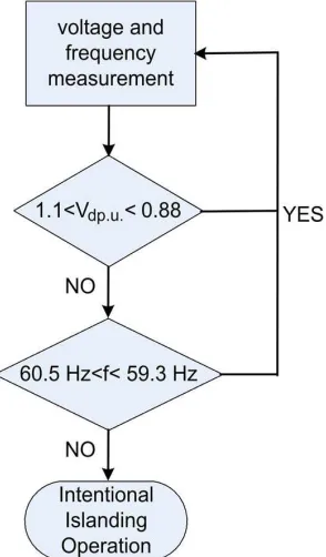
361 Islanding is the condition where the DG
[image:3.595.317.566.219.484.2]remains operating in the distribution system with the utility disconnected. In the past years, several islanding detection methods have been proposed and the detection methods can be categorized into two main groups: passive and active methods. Passive methods depend on measuring system parameters and then thresholds are set to these parameters to differentiate between an islanding and anon-islanding condition Active method directly interact with the power system operation by introducing perturbations in the inverter output. The most commonly used islanding detection method is the Over/Under Voltage (OVP/UVP) and Over/Under Frequency (OFP/UFP). [4],[8]
Fig.3:Intentional-islanding-detection algorithm
The DG interface control designed in this paper provides constant DG output and maintains the voltage at the Point of Common Coupling (PCC) at 1 p.u. Maintaining both the voltage and power constant during an islanding condition is not feasible for standalone operation of the DG since both depend on each other, and the OVP/UVP and OFP/UFP could be used to detect islanding[4]. This detection method will operate efficiently for large mismatches between load and DG capacity.
2. CONTROLLERS
The system consists of a micro source that is represented by the dc source. Under normal
operation, each DG inverter system in the microgrid usually works in constant current (or constant power) control mode in order to provide a pre-set power to the main grid. When the microgrid is cut off from the main grid, each DG inverter system must detect this islanding situation and switch to a voltage control mode. In this mode, the microgrid will provide a constant voltage to the local load[2].
[image:3.595.73.220.292.543.2]Condition I: GRID IS DISCONNECTED
Fig. 4: Voltage-controller -the Grid is disconnected
E-ISSN: 2321-9637
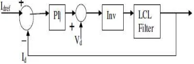
[image:4.595.85.284.117.368.2]362 Fig 5: Current Controller grid Connected
For grid-connected operation, the controller shown in Fig 5.Is designed to supply constant current output. A phase locked loop is used to determine the frequency and angle reference of the Point of Common Coupling (PCC) voltage. To simplify the design and operation of the controller, the control of the system is designed in a synchronous reference frame (SRF) [5]. Fig. 6 shows this control topology employing synchronous frame current control.[6] the inverter currents are transformed into a synchronous frame by Park’s transformation and regulated in dc-quantity corresponding to the current references Idqref. In the following stage, the voltage references in dc-quantities Vdq which being processed by PI controllers are transformed into a stationary frame by the inverse of Park’s transformation and utilized as command voltages for generating high frequency pulse width modulated (PWM) voltage.
Fig. 6: Block diagram of Current controlled Inverter
When using the current control, the output current from the filter is fed back and compared with reference current Iref and the error is passed to the PWM to generate voltage reference for the inverter. In order to get a good dynamic response Vdq is fed forward. Fig. 6 shows the block diagram of the DG interface control for grid-connected operation. For unity power factor operation, Iqref is set to zero.[2]
A. Intentional-Islanding Operation Mode
The control works as voltage regulation through current compensation. The controller uses voltage compensators to generate current references for current regulation. As shown, the load voltages (Vd and Vq) are forced to track its reference by using a PI compensator (voltage regulator). The outputs of this compensator (IDref and IQref ) are compared with the load current (IDandIQ), and the error is fed to a
[image:4.595.320.525.365.421.2]current regulator (PI controller). The output of the current compensator acts as the voltage reference signal that is fed
Fig 7: Synchronization Controller
to the sinusoidal pulsewidth modulator to generate the high frequency gating signals for driving the three-phase voltage source inverter. The current loop is included to stabilize the system and to improve the system dynamic response by rapidly compensating for near-future variations in the load voltages. In order to get a good dynamic response, VDQ is fed forward. This is done because the terminal voltage of the inverter is treated as a disturbance, and the feed forward is used to compensate for it .
B Synchronization for Grid Reconnection
[image:4.595.74.274.615.681.2]1) Assume that the phase difference between the grid and inverter voltages is given by
2) In order to obtain the information of voltage values are used
Using the variables k and g, sin(θ) can be found as
Fig.7 Synchronization control shows how
sin (θ) is used to obtain the new phase angle for which the grid and inverter voltages are synchronized.
Modeling Of Circuit InMatlab Simulink
Fig 8: Simulation model
3. SIMULATION RESULTS
The performance of the proposed control strategies was evaluated. Fig.8 shows the simulated system. 1) Assume that the phase difference between the grid
(6)
2) In order to obtain the information of θ, two sets of
(7) ) can be found as
(8) shows how
) is used to obtain the new phase angle for which the grid and inverter voltages are
Simulink
The performance of the proposed control strategies shows the simulated system.
This system was tested under the following conditions:
1. switching frequency 2. output frequency: 60 Hz; 3. filter inductor Li: 1 mH; 4. filter inductor LL: 0.5 mH; 5. filter capacitor Cf
6. dc-link voltage Vdc: 400 V; 7. o/p phase voltageVo 8. Output capacity: 10 KW.
The RLC load was adjusted to be resonant at 60 Hz and to consume 4.4 KW. The DG system was designed to supply 10 KW and zero reactive power. The system was operated initially in grid
operation. The grid was disconnected at 0.1second.The control mode was ch
current- to voltage controlledoperatio
Fig.9: Grid Voltage during Grid Connected to Islanding operation
Fig.10: Grid Voltage and Current from Grid Connected to Islanding
363 This system was tested under the following
switching frequency fs: 10 kHz; output frequency: 60 Hz;
: 1 mH; : 0.5 mH; Cf: 31 µF;
dc: 400 V; Vo1ϕ:120 Vrms; utput capacity: 10 KW.
load was adjusted to be resonant at 60 Hz KW. The DG system was designed to supply 10 KW and zero reactive power. The system was operated initially in grid-connected operation. The grid was disconnected at he control mode was changed from to voltage controlledoperation.
9: Grid Voltage during Grid Connected to
E-ISSN: 2321-9637
364 Fig.11: Grid Voltage & Current from island to Grid
[image:6.595.60.303.118.281.2]Connected
[image:6.595.315.537.326.475.2]Fig. 12: Phase voltage without Load shedding
Fig. 13: Phase voltage with Load shedding
The DG was operated in the synchronous island mode until both systems were resynchronized. As can be seen, the proposed algorithm successfully forces the voltage at the DG to track the voltage at the grid. Once the synchronization was completed, the DG was reconnected to the grid, and the controller was switched from the voltage to the current control mode. Fig. 12,13 shows the phase voltage Vawithout and with the load shedding algorithm implemented.
Case Study:
We have considered 3 test cases where we used same simulation model for 3 different cases. Lets analyze these cases one by one.
Case:1: 120V,60Hz,8Kw
Fig.14: Grid Voltage and Current from Grid Connected to Islanding for case 1
Simulation result for Case No 1 are as above. It is clear from above fig. that given system operates perfectly if we increased the load from 4.4 kw to 8 Kw keeping voltage and frequency same. It is providing constant voltage in island mode.
[image:6.595.71.300.329.518.2] [image:6.595.71.298.548.724.2]365 Fig.15: Grid Voltage and Current from Grid
Connected to Islanding for case 2
Now it is clear from fig 15 that if we change the grid voltage and frequency from 120V to 230V and 60Hz to 50Hz we are getting reduced voltage and current in island condition so we have to implement load shedding algorithm so that only critical load should be supplied.
Case No3: 230V,50Hz,8Kw
Fig.16: Grid Voltage and Current from Grid Connected to Islanding for case 3
From fig 16, if we change voltage,frequency and load in island mode we do not get constant voltage. So it is evident from case 1,2 and3 that given simulation model gives good results for the given voltage and frequency. If we want to change the voltage and frequency then we have to make changes in current and voltage controller as well as parameters of inverter and accordingly we have to
choose values of Kp and Ki of PI controller to get the desired results.
4. CONCLUSION
Here in this paper a controller is designed both for grid connected operation and the other for Intentional islanding operation. An algorithm for the detection of islanding is presented which was responsible for the switchbetween the two controllers and also a re-closure algorithm which causes the DG to resynchronize itself with the grid is also designed. Thus the paper summarizes the traditional independent inverter and Grid-connected inverter control strategy, combining the distributed power and microgrid inverter characteristics, a suitable microgrid inverter control strategy is put forward. Switching between connected mode and Grid-disconnected mode for microgrid inverter has been studied. On the Grid-disconnected operation microgrid inverter supplies the important loads that ensures load voltage and frequency stability. Microgrid inverter can smoothly switch between Grid-connected operation and Grid-disconnected operation, and switching operation of the system has good performance. The system controller design is simple, practical and efficient, easy to implement .In this paper we have considered different test cases.The simulation results show that the proposed control method is feasible and effective.
REFERENCES:
[1] Carpaneto, E.; Chicco, G.; Prunotto, A., “Reliability of reconfigurable distribution systems including distributed generation,” International Conference on Probabilistic Methods Applied to Power Systems, pages:1 – 6, 11-15 June 2006. [2] Irvin J. Balaguer, UthaneSupatti, Qin
Lei,Nam-Sup Choi, “Intelligent Control for Intentional Islanding Operation of Microgrids” ICSET 2008 [3] Irvin J. Balaguer, Qin Lei, Shuitao Yang,
UthaneSupatti, Fang ZhengPeng,” Control for Grid-Connected and Intentional Islanding Operations of Distributed Power Generation”, IEEE transactions on industrial electronics, vol. 58, no. 1, january 2011
[4] IEEE Std. 1547, “Standard for Interconnecting Distributed Resources with Electric Power Systems,” 2003.
micro-grids,” Electric Power Systems Research, Distributed Generation: Volume 77, Issue 9, pages 1204-1213, July 2007.
E-ISSN: 2321-9637
366 Power Systems, IEEE Transactions on, Volume
22, Issue 2, pages: 514 – 521, May 2007
[6] L. Qin, F. Z. Peng, and I. J. Balaguer, “Islanding control of DG in microgrids,”in Proc. IEEE 6th IPEMC, 2009, pp. 450–455.
[7] Thacker, T.; Wang, F.; Burgos, R.; Boroyevich, D., “Islanding Detection Using a Coordinate Transformation Based Phase-Locked Loop,” Power Electronics Specialists Conference, 2007, PESC 2007, IEEE, pages: 1151 – 1156, 17-21 June 2007
[8] Yun Wei Li, Member, IEEE, and Ching-Nan Kao,” An Accurate Power Control Strategy for Power-Electronics-Interfaced Distributed Generation Units Operating in a Low-Voltage MultibusMicrogrid”, IEEE transactions on power electronics, vol. 24, no. 12, december 2009