329
Performance Enhancement of Optical Communication
Using Decision Feedback Equalization
Amit kaushik
1, Hemant Dalal
2Department of Electronics and Communication1,2
CBS Group of Institutions1,2
Jhajjar, Haryana
Email [email protected], [email protected]
Abstract : This paper, proposes an adaptive equalizer by integrating the fractional spaced equalizer (FSE) with decision feedback equalizer (DFE) for optical channel to compensate the problem of pulse dispersion effect in optical link. The performance of the equalizer is improved by adopting the activity detection guidance (ADG) with tap decoupling (TD) in the fractional spaced decision feedback equalizer (FSDFE) to get fruitful outcomes. In this paper a fractionally spaced decision feedback equalization (FSDFE) structure which replaces the symbol spaced feedback filter with a fractionally spaced feedback filter is used to improve the stability and the steady-state error performance and the convergence rate. As the impulse response of a typical optical link would have regions that are essentially zero, the employment of the activity detection scheme with Tap Decoupling would further enhance the steady-state error performance and convergence rate. The simulation results revealed that: the FSDFE with ADG and TD offers a superior performance than its counterpart without ADG and TD. Where, it offers improvement in the effectiveness of amplitude distortion.
Index : ADFE, ADG, DFE, FSE, FSDFE, I.S.I and TD
I. INTRODUCTION
In Long haul optical communications usually there are several keys area to ensure the data transfer is error-free. These areas include modulation method, type of amplifier used, and the error correction scheme and dispersion compensation. In optical communications, high-speed data transfer is limited by signal distortion, caused by the broadening of pulses that result in Intersymbol Interference (ISI).
There are several forms of dispersion, such as: Intermodal dispersion that occurs only in multimode fiber due to different velocities for different modes and hence, it reduces the performance of optical network at higher data rates. The second one is intra-modal dispersion which occurs in all types of fibers. Intra-modal dispersion occurs because different colors of light travel through different materials and different waveguide structures at different speeds. Intra modal dispersion is also called as chromatic dispersion (CD) which can be divided into two parts: the first one, is called material dispersion that limits the fiber bandwidth or the information-carrying capacity of the fiber and also limits the transmission distance, since the shorter the pulses, the more susceptible they are to lSI. The second type is the waveguide dispersion occurs because the single-mode fiber only confines about 80 percent of the optical power to the core. Thus dispersion arises due to light propagating in the cladding travels faster than the light confined to the core. So, dispersion occurs because light propagates differently in the core than in the cladding. The intra modal dispersion can be expressed mathematically by
Dintramodal = Dm+ DWG
where: D M is the material dispersion, DWG is the waveguide dispersion.
The numerous techniques in adaptive equalization and equalizer are used that gives suitable and effective equalization approach for a typical optical channel. In this paper we evaluate the causes of dispersion in a typical optical link and its limiting effects to the possible communication capacity, then to reverse the effects that the channel has on the transmitted signal and reproduce the original signal at the received end. Finally, design an adaptive equalizer to mitigate the pulse dispersion effects of an optical link. A range of adaptive algorithms and equalizer structures are evaluated. The Least Mean Square (LMS) algorithm is chosen for its robustness and computational simplicity.
II. ADAPTIVE EQUALIZER
Linear equalizer is not allways useful for high data bit rate with a dispersive optical channel suffers from lSI or amplitude distortion and used where, the channel does not suffer from amplitude distortion. On the other hand, non-linear equalizer approved its capability to provide superior performance in amplitude distorted channel and will be very beneficial and relevant to the application in optical communications.
330
communication link [1]. It is defined as the equalizerwhich adjusts to different environments and involves a process of filtering input signal to match a desired response. Its parameters are automatically updated by making a set of measurements of the underlying signals and applying that set to the adaptive filtering algorithm such that the difference between the output and the desired response is minimized in either a statistical or deterministic sense [2]. Concerning the adaptive algorithms, we have several numbers of adaptive algorithms, The most important of them are the least mean squares (LMS) error algorithm and recursive least squares (RLS) algorithm. The criterion used in the adaptive LMS algorithm is the minimization of the mean square error (MSE) between the desired equalizer output and the actual equalizer output in [1 0] for the N-taps adaptive transversal filter and the output is given Nyquist rate. Such equalizers have taps that are spaced closer than conventional adaptive equalizers, and with a sufficient number of taps, it is almost independent of the channel delay distortion. It means that the equalizer can negate the channel distortion without enhancing the noise [3]. Given the above properties, the FSE technique is a highly desirable application since it minimizes noise enhancement. With appropriately chosen tap spacing; the FSE can be configured as the excellent feed forward filter. The combination of DFE with FSE technique, provides minimize noise enhancement and Excellent amplitude distortion performance.
Decision Feedback Equalizer
Decision Feedback Equalizer have both the feed forward and feedback filters are essentially linear filters. It is a linear structure because of the non-linear operation in the feedback loop (decision threshold); its current output is based on the output of previous symbols. The decision feedback equalizer has zero noise enhancements in the feedback loop. The
The output of the equalizer is given by:
^=∑ ∗ ∑
where is the tap gain and y x n c
n is the input for the forward filter,is the tap gain for the feed back filter and
dFi x (i<k) is the previous decision made on the detected signal [4].
Activity Detection Guidance
Activity detection guidance technique is a method of detecting active taps in a communication channel, implementing such technique capable of detecting active taps in the channel, non-active taps can be excluded in the estimation of the channel response. This gives a better convergence rate and asymptotic performance. The detection of the ‘active’ taps of a time-invariant channel is governed by the equation [6].
, = ∑# . !" certain threshold. The activity threshold is given by:
$%, > ' ( ). log
Modifications to the activity measure have to be made to reduce the tap coupling effect [6].
$$ =∑ [ . /0! !" . 1 !" ]
∑# 1 !"
III. Analysis of Impulse Response in Optical Channel
The frequency response of the base band is given by
H(f)=345 678 678 9
: : 7;8;<
And the impulse response of a typical optical channel represented by a cosine-squared pulse shape and is
331
channel. It is clear that the channel bears a fairresemblance of the simulated channel. But, the inactive taps, which were supposed to be zero, were not flat. This is due to the noisy estimates of the inactive taps in the channel.
Fig. 1: Impulse response with FSDFE after simulation
Fig. 2: Estimated channel impulse response for FSDF
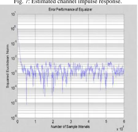
Fig. 3: Asymptotic perfornance for FSDF
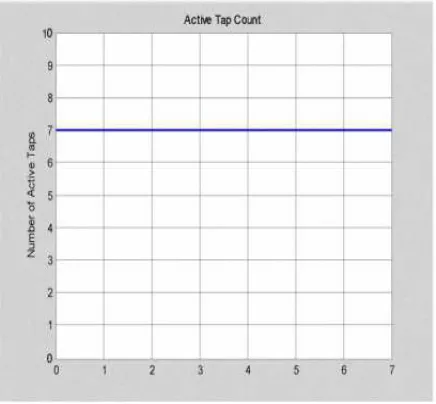
Fig. 4: Active taps count for FSDFE.
Fig. 5: Squared difference of input to channel and output of equalizer for FSDFE.
FSDFE with ADG and Tap Decoupling.
332
Fig. 6: Simulated channel impulse response.Fig. 7: Estimated channel impulse response.
Fig.8: Asymptotic performance of the equalizer.
Fig.9: Active taps count.
Fig.10: Output of equalizer V. CONCLUSION
With the successful development of the adaptive modified Decision Feedback Equalizer with activity detection guidance and tap decoupling, it offers an excellent alternative to the existing equalization techniques available in the optical communication is implemented using the Least Mean Square (LMS) technique, using stochastic gradient adaptation, led to a faster convergence rate, as only the active taps need to be adapted, and better asymptotic performance as shown clearly.
REFERENCES
[1] Theodore S. Rappaport, “Wireless Communications
– Principles and Practice” 2nd edition, Prentice Hall Communications Engineering and Emerging Technologies Series, Upper Saddle River, New Jersey, 2002.
333
[3] John M. Senior, "Optical Fiber Communications -Principles and Practice" 2nd edition, Prentice Hall International Series in Optoelectronics, New York, 1 992.
[4]S.D. Personick, "Time dispersion in dielectric waveguides", Bell Syst. Tech. J., 50(3), pp. 843-859, 1 971 .
[5] Simon Haykin, "Adaptive filter theory", Prentice-Hall, Upper Saddle River, N.J, 1 996