,
l
1
I
-- -- -- --
-
-
-
- - --
-
----- ----
-
---
--- --- _ .
-GC34-0121-0
S1-20
PROGRAM PRODUCT
IBM Series/1
Program Preparation Subsystem
Introduction
Program Number 5719-AS1
1
0
1'-,
J*
.
:f.C
..c::.
--:ra
l
0
fEE
:
cOl
II
11111111111111111111111111111111111111111111111
0
[]
111111111111111111111111111111111111111111111111
0
~
w~~
.J- 0rn
0[]
1111111111111111111
~
0
[[]
I
111111111111111111111111111111111111111111111111
~(
z
./(1]
Series/
1
- - -
----
-
--
--
-----
-
-
---
_ .-c
o
GC34-0121-0
51-20
IBM Series/1
PROGRAM PRODUCT
Program Preparation Subsystem
Introduction
Program Number 5719-A51
This publication is for planning purposes only. The information herein is subject to change before the products described become available.
First Edition (February 1977)
This manual applies to the IBM Series/l Program Preparation Subsystem, 5719-ASl.
Significant changes or additions to the contents of this publication will be reported in subsequent revisions or Technical Newsletters. Requests for copies of IBM publications should be made to your IBM representative or the IBM branch office serving your locality.
A form for readers' comments is provided at the back of this pUblication. If the form has been removed, send your comments to IBM Corporation, Systems Publications, Department 27T, P.O. Box 1328, Boca Raton, Florida 33432. Comments become the property of IBM.
©Copyright International Business Machines Corporation 1977
ii GC34-0121
o
c
c
Preface v
How This Book is Organized v Related Publications vi
Programming Publications vi Hardware Publications vi
Chapter I. Overview of the Series/l Program Preparation Subsystem 1-1
The Subsystem Components 1-2 The Job Stream Processor 1-2 The Text Editor 1-4
The Macro Assembler 1-5 The Application Builder 1-6
Using the Subsystem Components in Program Preparation 1-8 Typical Uses of the Program Preparation Subsystem 1-8
Using the Subsystem Programs in the Realtime Environment 1-10
Preparing Programs for Execution Under Your Own Supervisor 1-10
Using the Subsystem Programs in a Batch Environment 1-11 Problem Solving with the Compile, Load, and Go Facility 1-12 Invoking and Executing the Subsystem Programs 1-13
Data Sets and Devices Used by the Subsystem Programs 1-14 The Required Data Set Definitions 1-14
Work Data Sets 1-15 Environment Lists 1-16 Req uired Hardware 1-16
Installing the Program Preparation Subsystem 1-18 Chapter 2. The Job Stream Processor 2-1 The Job Input Stream 2-1
Jobs and Steps 2-1
Data Set Definition Statements 2-2 DSD Environment 2-2
Compile Load and Go Statements 2-3 Input Data 2-4
Sources of the Input Stream 2-4 Redirecting the Input Stream 2-5 Which Input Stream Source to Use 2-6
Summary of Job Stream Processor Control Statements 2-6 Summary of Job Stream Processor Features 2-7
Chapter 3. The Text Editor 3-1 Using the Text Editor 3-2
Interactive and Noninteractive Use 3-2 Line Numbers 3-2
Tailoring the Editing Session 3-3 Preserving Editing Sessions 3-4 Defining Editor Data Sets 3-5 Invoking the Editor 3-5 The Editor Commands 3-6 Summary of Text Editor Features 3-7
Chapter 4. The Macro Assembler 4-1 The Assembler Program 4-1
Defining Assembler Data Sets 4-1 Invoking the Assembler 4-2 The Assembler Language 4-3
Machine Instructions 4-3 Assembler Instructions 4-3 Macro Instructions 4-5 Assembler Coding Features 4-7
Contents
Symbolic Representation of Program Elements 4-7 Variety of Data Representation 4-7
Relocatable Object Mod ules 4-7 Address Assignment 4-7 Flexible Register Usage 4-7 Program Sections 4-7
Symbolic Linkages Between Separately Assembled Source Modules 4-8
Comprehensive Assembler Listings 4-8 Structured Macro Usage 4-9
Summary of Macro Assembler Features 4-10 Chapter 5. The Application Builder 5-1 Execution Environments Supported 5-1
An Environment You Provide 5-2
The Realtime Programming System Execution Environment 5-3 Application Builder Processing 5-6
Phase 1 Processing 5-6 Phase 2 Processing 5-8 Phase 3 Processing 5-11
Summary of Application Builder Data Sets 5-13 Invoking the Application Builder 5-13
Listing and Processing Options 5 -14
Summary of Application Builder Features 5-15 Appendix A. Configuration Requirements A-I Hardware A-I
Storage Requirements A-I Disk Requirements A-I
Diskette Requirements A-2
Timer Requirements A-3
Printer Requirements A-3
Programming Requirements A-3
Compatibilities A-3
The Base Program Preparation Facilities and the Program Preparation Subsystem A-3
The Realtime Programming System and the Program Preparation Subsystem A-4
Appendix B. Using the Series/I Programming Library B-l Glossary G-l
Index X-I
,
,
c:
c
Preface
This book provides introductory information about the IBM Series/l Program Preparation Subsystem for the reader who is evaluating the subsystem for applicability to his installation, as well as for the reader who simply wants a general understanding of the subsystem facilities.
The reader should have a basic knowledge of programming systems and be familiar with the information in the IBM Series/l Realtime Programming
System: Introduction and Planning Guide, GC34-0102.
How this Book is Organized
Chapter 1. Overview of the Program Preparation Subsystem. This chapter describes the purpose, organization, functions, and operating environment of the components of the Program Preparation Subsystem.
Chapter 2. The Job Stream Processor. This chapter explains how the job stream processor control statements are used to invoke batch programs and define the data sets and devices required by those programs.
Chapter 3. The Text Editor. This chapter explains how the text editor is used to create, modify, list and save text modules.
Chapter 4. The Macro Assembler. This chapter describes assembler language features and explains how the assembler program is used to create relocatable object modules.
Chapter 5. The Application Builder. This chapter explains how the application builder processes object modules to prepare them for execution as application programs.
For each of these components, there is a description of its purpose, data sets and devices used, the input required, the processing sequence, and the output created. Each of these chapters also directs the reader to the appropriate manual for more detailed information about the component.
Appendix A. Configuration Requirements. This appendix contains information about hardware and software requirements and compatibilities.
Appendix B. Using the Series/1 Programming Library. This appendix is a
quick-reference guide to help you determine the other Series/l manuals you may need for various types of programming activities.
A glossary is provided to define terms referenced in this manuaL
Related Publications
Programming Publications
Hardware Publications
vi GC34-0121
The following hardware and programming publications contain more detailed information about topics covered in this book.
Note. Order numbers are shown only for the publications that are available at
this time.
IBM Series/l Program Preparation Subsystem: Batch User's Guide IBM Series/l Program Preparation Subsystem: Text Editor User's Guide IBM Series/l Program Preparation Subsystem: Macro Assembler User's Guide,
SC34-0124
IBM Series/l Program Preparation Subsystem: Application Builder User's Guide
IBM Series/l Realtime Programming System: Introduction and Planning Guide,
GC34-0102
IBM Series/l FORTRAN IV: Introduction, GC34-0132
IBM Series/l PL/ I: Introduction, GC34-0084
IBM Series/l Mathematical and Functional Subroutine Library: Introduction,
GC34-0138
IBM Series/l Model 5 4955 Processor and Processor Features Description,
GA34-0021
IBM Series/l Model 3 4953 Processor and Processor Features Description,
GA34-0022
IBM Series/l 4962 Disk Storage Unit Description and 4964 Diskette Unit
Description, GA34-0024
IBM Series/l 4973 Printer Description, GA34-0044
IBM Series/l 4974 Printer Description, GA34-0025
IBM Series/l 4979 Display Station Description, GA34-0026
IBM Series/l System Summary, GA34-0035-1
(
,
"\c
c
Chapter 1. Overview of the Series /1
Program Preparation Subsystem
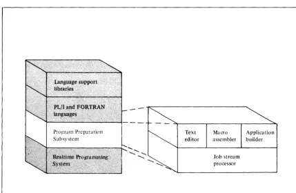
The Program Preparation Subsystem is a set of programs in the IBM Series/l software system that offers:
• A general-purpose disk-based job stream processor.
• Powerful program preparation facilities for creating realtime and batch applications.
The job stream processor reads, analyzes, and processes the job input stream, which is a sequence of your requests for invoking batch programs and defining the data sets and devices they use.
The program preparation facilities-the text editor, macro assembler, and application builder-allow you to create, update, and assemble source programs, and then build executable application programs.
The programs that make up the Program Preparation Subsystem will also be referred to in this manual as the subsystem programs or the subsystem
components.
You can also use PL/I, FORTRAN IV, and the Mathematical and Functional Subroutine Library (MFSL) with the subsystem programs. Information about the Series/l software-the program products and how they form a total system-is contained in the IBM Series/l Realtime Programming System: Introduction and
Planning Guide, GC34-0 1 02.
Figure I-\. The IBM Series/l software system
Text Macro Application editor assembler builder
Job stream processor
[image:8.621.136.566.396.676.2]The subsystem programs can run concurrently with realtime applications under the realtime supervisor or, in the absence of realtime applications, can run under the realtime supervisor in a simple batch environment. Batch processing provides a convenient method of invoking and executing programs, with little or no operator intervention required.
The Subsystem Components
The Job Stream Processor
1 - 2 GC34-0121
Each of the components in the Program Preparation Subsystem performs functions that allow you to prepare programs for execution-in the Realtime Programming System execution environment or in an environment you provide. The following section introduces the features and functions of each of the components to give you some background information about the component before you read the individual chapters describing each component. It covers the:
• Job stream processor. • Text editor.
• Macro assembler. • Application builder.
The job stream processor, which serves as the interface to the system resources, provides a simple set of control statements for invoking the programs and for defining data sets they use. These control statements and related data make up a job input stream composed of jobs and steps. Upon reading the control
statements (such as JOB, EXEC, and PARM) the job stream processor analyzes the parameters you supply and processes your requests for executing programs. It also manages the data sets and devices used by the programs and handles the automatic job-to-job, step-to-step transition during job input stream processing.
The job stream processor provides the facility to:
• Specify your work requests to the system, using a simple control language. • Process a job input stream of work requests, the source of which may be an
operator station or a previously-created data set.
• Start the input stream from one device and redirect it to another device. For example, you could start the primary input stream from an operator station, then switch to a secondary input stream on a disk data set.
• Use data set definition (DSD) statements to define data sets and devices required by the subsystem programs or your own programs.
• Specify a group of data set definitions to be in effect at various levels of input stream processing-session level, job level or step level.
• Predefine lists containing all of the data set definitions (DSDs) required for executing particular jobs. These environment lists can be prepared and stored on the system. Jobs that require them can then refer to the appropriate environment list, and the job stream processor will process the DSDs as if you had entered them in the input stream.
• Use special control statements -ASMGO, FORTGO, or PLIGO-to initiate a "compile, load, and go" sequence. This lets you translate, build, and execute a program with a minimum of effort.
• Run the Realtime Programming System utilities under the Program Preparation Subsystem.
( \
c
c
D
Source of the input stream
The job input stream
Allocating resources in the input stream
DSDs for required work data sets - - - ' "
DSD for output data set A B C
-DSD for listing o u t p u t - - - -....
DSD for system logging device
-DSD for message logging device --~
JOBI STEPl
•
•
•
JOB
EXEC
•
•
ENVL refers to TSN=
Changing the source of the input stream
[image:10.620.80.568.59.500.2]ALTER - - - " " "
Figure 1-2. Using the job stream processor facilities
The Text Editor
1 - 4 GC34-0121
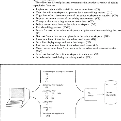
The text editor allows you to create, modify, list, and save text modules. These
text modules can consist of previously-prepared job input streams, source ( '\ statements, or input data to a batch program. You can use the editor in an \. j
interactive mode, entering text and commands from an operator station, or you can use it in a noninteractive mode by defining a disk or diskette data set as the input source.
Using the editor, you can create a new text module or retrieve and update an existing text module. The actual editing takes place in two work data sets, referred to as the editor workspace. The output from the text editor is a newly-created or updated text module that can be saved on a disk or diskette data set and later used as input to a language translator or one of your own application programs.
The editor has 15 easily-learned commands that provide a variety of editing capabilities. You can:
Replace text data within a field in one or more lines. (CF)
• Clear the editor workspace to prepare for
a
new editing session. (CL) • Copy lines of text from one area of the editor workspace to another. (CO) • Display the current status of the editing environment. (CS)• Change a character string in one or more lines. (CT) • Delete one or more lines in the editor workspace. (DE) • End the editing session. (END)
• Search for text in the editor workspace and print each line containing the text. (FI)
• Get text from a data set and place it in the editor workspace. (GE) • Insert new lines of text into the editor workspace. (IN)
• Set a line display range and set a line length. (LF)
• List one or more text lines of the editor workspace. (LI) f \, • Move one or more lines from one area in the editor workspace to another. , ,
(MO)
• Save text lines of the editor workspace to a data set. (SA) • Set tabs to be used during an editing session. (T A)
Establishing an editing environment
CS
LF
TA
CL
Retrievin/{ text modules
GE
Modifyin/{ text
CF DE MO
CO FI
CT IN
Listing text
Ll
Saving text
SA
Ending an editing session
END
Text
[image:11.620.54.547.210.702.2]editor
Figure 1-3. Program preparation-the text editor (part 1 of 3)
Source
The Macro Assembler
c
c
c
Once source statements have been created, the next step in the program
preparation sequence is a language translator. The macro assembler is a powerful language translator that provides:
• A function-oriented assembler language for specifying machine instructions. • A flexible macro language facility.
• Conditional assembly capability within macros. • Sectional assembly capability.
• Assembler options for data definition and listing control. • Relocatable object module output.
• Listing output that can include the source program and object text, external symbol dictionary, relocation dictionary, cross-reference table, error messages, and statistics.
The main purpose of the assembler program is to process source statements and create one or more relocatable object modules. These object modules consist of machine instructions and information that will be used by the application builder in its processing.
Note. Using the PL/I and FORTRAN IV program products in program preparation is described in the IBM Series/l PL/I: Introduction, GC34-0084 and the IBM Series/l FORTRAN IV: Introduction, GC34-0132.
Source statements
Macro assembler
Figure 1-4. Program preparation-the macro assembler (part 2 of 3)
[image:12.620.194.563.328.471.2]The Application Builder
1 - 6 GC34-0121
The application builder provides a variety of services that can be used in creating
an application program for execution in the Realtime Programming System ( \ environment or in an environment you provide. How you use these services will \. ; depend on the execution environment for which you are preparing the application
program.
To execute in the realtime environment, an application program must be in the form of a task set. A task set is a planned program structure that consists of one or more modules grouped together and combined with various tables and control blocks (a control module) required by the realtime supervisor. To execute in an environment other than the realtime environment, an application program must be a load module in absolute format.
To create an application program, in the form of a task set, to execute in the Realtime Programming System environment, the application builder:
• Processes control statements that allow you to select the options and data set environment to perform the functions required.
• Assigns storage addresses and resolves external references to create a
composite module in relocatable format, which will later become part of a task set.
• Produces composite modules that may be structured in a single segment (simple structure) or multiple segments (overlay structure).
• Provides a recycling capability to process multiple sets of control statements, where each set of statements creates a composite module.
• Can include modules automatically from a program library through an autocall facility.
• Creates a control module, which specifies the control blocks required by the Realtime Programming System, at application build time rather than at
execution time. (This control module resides in your task set at execution
t
1\time.) " ,
• Creates a prebind module, which allows you to specify the resources to be pre bound to a task set when it is installed rather than at execution time. This pre binding of resources will allow your task set to begin executing faster. To create an absolute load module that is executable in an environment you provide, the application builder:
• Processes the control statements you specify to identify the contents, structure, and name of the absolute load module.
• Processes object modules to create absolute load modules that consist of a single segment. Addresses are assigned relative to the specified origin for that module, as well as having external references between the object modules resolved.
(
...c
c
c
Using the application builder to create an application program to execute in an environment other than that of the Realtime Programming System.
Application builder (phase 1)
Using the application builder to create an application program to execute in the Realtime Programming System environment.
Applica tion builder (phase I)
Applica tion builder (phase 2)
*optional
Application builder (phase 3)
9
~
Figure 1-5. Program preparation-the application builder (part 3 of 3)
[image:14.617.100.563.50.480.2]Using the Subsystem Components
in
Program Preparation
A major use of the subsystem components is preparing programs for execution under the realtime supervisor or your own supervisor.
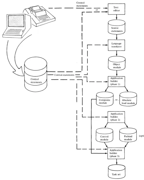
The basic steps involved in creating an application task set are:
1. Use the job stream processor to manage the program preparation environment.
2. Use the text editor (or IBM 3741 Programmable Work Station) to create the source code.
3. Use the macro assembler or a compiler to translate the source code and create object modules.
4. Use the application builder to create composite modules or absolute load modules. (If you are creating an absolute load module to execute under your own supervisor, you can skip steps 5 and 6.)
5. Use the application builder to create a control module and (optionally) a pre bind module.
6. Use the application builder to create an application task set that can be executed in the Realtime Programming System environment.
Figure 1-6 shows the sequence of steps in creating an application task set.
Typical Uses of the Program Preparation Subsystem
The facilities of the Program Preparation Subsystem meet the requirements of a wide range of users. Typical uses of these facilities include:
• Preparing application task sets to run under the realtime supervisor in a realtime environment.
• Creating your own supervisor and preparing programs to run under that supervisor.
• Using the subsystem programs in a batch environment.
• Using the compile, load and go capability for problem-solving purposes.
Us;"g the Subsystem Programs in the Realtime Environment
I - 8 GC34-0121
Typically, you would create programs and data using the text editor, then store them on permanent data sets. The source statements are compiled or assembled to create object modules, which must undergo application builder processing to build your realtime application.
To execute under the realtime supervisor, an application must be in the form of a task set. Phases 1, 2, and 3 of application builder processing are required to create task sets that are executable in the realtime environment. Figure 1-6 illustrates this processing.
The subsystem programs may execute concurrently with your realtime applications.
(
'\C
Control statements
- - - - -
Textor editor
r
-I
I
I
I
I
I
I
I
I
I
I
---.-J
~L_
: I
C
I
I
I
I
I
L
I
I
I
(optional)L_
c
Figure 1-6. Program preparation sequence [image:16.617.75.553.101.695.2]Preparing Programs for Execution Under Your Own Supervisor
/ '
Control statements
((tatements
Text editor
1 - 10 GC34-0121
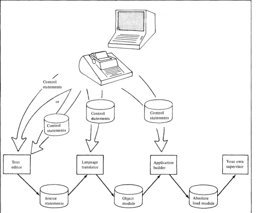
In this case, you prepare programs in much the same manner as you would for the Realtime Programming System, with one exception. Instead of creating programs, in the form of task sets, to execute under the realtime supervisor, you create absolute load modules to execute independently or under your own supervisor.
Phase 1 of application builder processing can create these absolute load modules. However, none of the Realtime Programming System support functions can be requested, and you must provide a means of loading the programs into storage and passing control to them. The Disk IPL Bootstrap Loader, which is described in the IBM Series/l Stand-Alone Utilities User's Guide, GC34-0070, can be used for loading a program and passing control to it.
Figure 1-7 illustrates this processing.
ij
~
Language Application Your own
translator builder supervisor
Figure 1-7. Preparing programs for execution under your own supervisor
(
\ [image:17.617.46.562.251.679.2]C
··~~
c
o
Using the Subsystem Programs in a Batch Environment
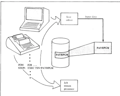
You may use application programs that you have created to run in a batch environment. Application program input, stored in data sets, can be prepared or updated by using the text editor. The data set can be passed to the application program through the job stream processor.
For example, you may have a payroll program residing on a data set.
Periodically you would use the text editor to enter such data as overtime for the last period of time. This data and the appropriate job stream processor control statements would then be entered in the job input stream for processing by your payroll program.
o
\
•
JOB1 JOB
STEP1 EXEC TSN=PA YRPGM
~:
•
Text editor
Job stream processor
Input data
Figure 1-8. Using the subsystem programs in a batch environment
PAYRPGM
[image:18.617.177.568.195.508.2]Problem Solving with the Compile, Load, and Go Facility
I - 12 GC34-0121
The Program Preparation Subsystem provides a simple method for performing
problem solving activities through the compile, load, and go facility. This allows ( .~ you to compile or assemble a program, build a task set, and execute that task set , by specifying a few simple control statements. The DSD statements identifying
the required data sets and devices are defined in advance in an environment list.
(Compile, load, and go is described in the job stream processor chapter of this manual.)
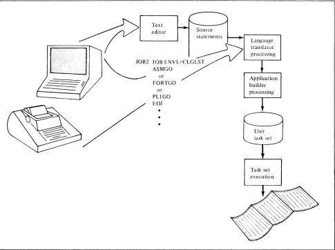
Typically, you would write a small program in a high level language, enter this program through the text editor, and then use the appropriate statement
(ASMGO, PLIGO, or FORTGO) to perform a compile, load, and go. Usually you would only be interested in the printed output and would not need to save object data or to specify intermediate input, output, or disk space requirements. Figure 1-9 illustrates the use of the compile, load, and go facility. CLGLST refers to a previously-prepared environment list.
Text edi tor
~2
or FORTGO
or PUGO EO]
•
Language translator processing Applica tion builder processing
Task set execution
Figure 1-9. Example of using the compile, load, and go facility
(
'\,
~ [image:19.612.60.545.253.615.2]c
c~
c
Invoking and Executing the Subsystem Programs
o
The subsystem programs run under control of the Realtime Programming System as realtime applications in a predefined, fixed partition. The text editor, macro assembler and application builder are all task sets that are invoked through the job stream processor, which is also a task set.
To begin a batch session, you must invoke the job stream processor by entering a system command-TSET STR, CPJ, ptn, qprty-at the operator
station. This command starts the job stream processor task set (CPJ), specifies the number of the partition in which the job stream processor is to execute (ptn), and establishes the queuing priority of the job stream processor (qprty). The job stream processor is then loaded and starts processing the input stream. The input stream, which consists of control statements and related input data, is logically subdivided into jobs and steps. The step is the basic unit of work in which you can specify the EXEC control statement to invoke a batch program.
Figure 1-10 illustrates this sequence.
TSET STR, CPJ, ptn, qprty
JOBl JOB.
STEPl I:XEC TSN = CPA
EO]
Realtime
applications
Batch partition
A<;sembler
Job stream processor
1. Issue the system com-mand TSET STR ... to start the job stream processor.
2. The job stream processor is loaded and starts processing the input stream. It reads a request to invoke the assembler (STEPI ... ).
3. The job stream processor queues itself to the batch partition, and the assembler is loaded. After the assembler terminates, the job stream processor is the next task set to get con trol.
- fub
7tr~l;I
processor I
L - -_ _ _ _ _ - - - - i _ ~~ei
_
-IFigure 1-10. Invoking and executing the subsystem programs
Note. The batch partition is not reserved for the subsystem programs. Realtime applications use it either when the subsystem programs are inactive or by
preempting the partition during a batch processing session.
[image:20.615.67.568.263.602.2]Data Sets and Devices Used by the Subsystem Programs
In the input stream there can be a variety of requests to execute programs-the
text editor, the assembler, the application builder, PL/I, FORTRAN IV, or your ( " own batch programs. Each of these programs uses certain data sets and devices \.. J
to make up its operating environment. You can specify these resources to the program through data set definition (DSD) statements. DSD statements are used to establish a connection between a data set or device and a DSD name used in a program.
You can use DSD statements to create new data sets, identify existing data sets or delete data sets that are no longer needed. The length of time the DSD is in effect depends on where it is located in the input stream-in a step, in a job, or at the beginning of a batch session.
The Required Data Set Definitions
IN STREAM
JSPWORK
MSGLOG
1 - 14 GC34-0121
Certain DSDs are established when the Program Preparation Subsystem is installed to make required data sets available to the job stream processor when you start a batch processing session.
To simplify the installation process, default DSDs are supplied for the required data sets at installation time. You can change any of these DSDs if they do not suit your needs.
The required data set information and DSD names are summarized here. The data sets and devices described are those that are required by the job stream processor and, therefore, by all components invoked through the job stream processor. For information about the required data sets and devices that are unique to each component-the text editor, macro assembler, or application builder-refer to the chapter describing that component.
The INSTREAM DSD defines the input stream source. Unless you specify another input source in the P ARM field of the task set start command, the job stream processor always reads the input stream from the device defined by INSTREAM.
The default IN STREAM device is the operator station.
JSPWORK defines a disk data set in which the job stream processor saves its control blocks when it relinquishes the batch partition to another task set.
MSGLOG defines the messages log device or data set that the job stream processor and text editor use for writing prompts and messages when in the interactive mode. The device assigned to MSGLOG should be the same as the IN STREAM device.
The default MSGLOG device is the operator station.
The device specified by the PRINT DSD is used by all of the subsystem programs for listing various types of printed output that you need in hard copy form.
(For example, the assembler and application builder print their listings and maps at the device defined by PRINT.)
The default PRINT device established at installation time is the printer.
SPOOL
c
o
c
Work Data Sets
o
The disk volume defined by the SPOOL DSD is used by the job stream
processor to handle your inline input data for the batch programs. When the job stream processor is processing the input stream and encounters your input data for a batch program, it automatically creates a data set on the SPOOL volume and transfers the inline data to that data set before the batch program is invoked.
Processor storage
Job
stream processor
JSPWORK
SPOOL
Figure 1-11. Default DSDs for required data sets and devices common to all subsystem components
The text editor, macro assembler, and application builder all require work data sets in order to perform their processing. Each of these components requires a different size and number of work data sets. You can specify the space required for a work data set by:
• Using individual DSD statements to indicate a specific volume and a specific amount of space for the WORKI-WORKx data sets.
• Using the WORKVOL DSD to define space for all the work data sets (WORKI-WORKx) and the volume on which the space is to be allocated.
Note. The DSD statements for WORKI-WORKx must always be specified for the assembler and for the application builder, whether or not you use the
WORKVOL DSD. The operands you specify on these statements will vary, depending on the use of the WORKVOL DSD. The text editor only requires that you specify the WORKVOL DSD.
To maximize workspace efficiency, you can use the WORKVOL DSD to define a volume to which all available space will be allocated. Each component can then dynamically allocate this space between the number of the work data sets it needs and in the proportion it needs.
[image:22.617.72.563.139.445.2]Environment Lists
Required Hardware
1 - 16 GC34-0121
For example, suppose you were to specify the WORKVOL DSD (to create a temporary work volume) and dummy work data sets-WORKi, WORK2, and WORK3-for assembler processing. The assembler, which requires three work data sets, would allocate the space among WORKi, WORK2, and WORK3. Work data set requirements for each component are summarized in the individual chapters describing the component.
Once the Program Preparation Subsystem is installed, you can also specify data sets to contain lists of DSDs that the job stream processor will use to create the environments for various batch programs. These environment lists can contain all the DSDs required to execute a job or step.
Many jobs can effectively use environment lists. For example, if you use the compile, load, and go facility, you should have environment lists prepared for the compile, load and go jobs. You might also want to prepare environment lists for jobs that use the program preparation facilities.
The chapters covering the text editor, macro assembler, and application builder give you more specific information about the data sets and devices used by each of these components. This information should help you to plan the data set and device assignments most efficient for your system and to set up the appropriate environment lists.
The minimum hardware configuration for the Program Preparation Subsystem is the same as is required for the Realtime Programming System:
Required hardware Product name
Processor One IBM 4953 Processor or IBM 4955 Processor with at least 48K bytes of processor storage.
Disk/ diskette One (or more) IBM 4962 Model 2 or Model 2F Disk Storage Unit (combination disk/diskette unit).
or
One (or more) IBM 4962 Model 1 or Model 1 F Disk Storage Unit
and
One (or more) IBM 4964 Diskette Units
Printer One (or more) IBM 4973 Line Printers or IBM 4974 Printers
Operator station One (or more) IBM 4979 Display Stations
or
Teletype* Model ASR 33/35 or an ASCII equivalent device that can be used an an operator station and is attached to the system through the Teletypewriter Adapter Feature #7850.
*Trademark of the Teletype Corporatioon
{
annn
ITIIIIIl111111111111
IH-t++t++11
I~
,
r
I!I
" I II I I I I
c
UIIIl
UIID
II I I I I I
rn
m
I1IIOJ
I I I I I I
-
-c
Timers may optionally be used with the subsystem programs.
For information about sensor I/O and communications support, which are not supported by the Program Preparation Subsystem, refer to the IBM Series/l
Realtime Programming System: Introduction and Planning Guide, GC34-0102.
mn:n
UIllD
' " I " II "
@)
11111111
"J
0
m
13
11111111 II
IIITID
UIIIIJ
(jJ
[]
11111 " I I
•
•
Figure 1-12. Sample hardware configurations
[image:24.618.71.562.115.605.2]Installing the Program Preparation Subsystem
1 - 18 GC34-0121
Once you have determined your data set and device requirements and the required hardware configuration, you can prepare to install your Program Preparation Subsystem. Before the subsystem programs can be installed, you must have already performed a system generation for the Realtime Programming System. The subsystem programs are installed in a stand-alone environment, and the installation process requires 48KB of processor storage.
The installation package you receive from IBM contains diskettes that contain the information required for converting the IBM-supplied code into task sets designed to run in the batch partition.
IBM also supplies a generation program that prompts you to supply information about the system to be built. To simplify the installation process, defaults are provided for all of the required DSDs. If you accept these defaults, the system can be installed as is. If you do not want to accept the defaults, you can make changes to the DSDs through your responses to the generation program prompts.
After you have supplied the information requested by the generation program, a job input stream will be generated. When this job input stream is executed, you will have a Program Preparation Subsystem tailored to your requirements. The generation program can also perform a system verification to ensure that your system is properly installed. System verification can only be performed against a complete Program Preparation Subsystem.
Although the Program Preparation Subsystem requires only a 16KB partition for execution of batch programs, you may want the partition to be larger for program preparation activity. This would make more efficient use of the system because the text editor, assembler, and application builder execute faster in a larger partition.
The IBM Series/l Program Preparation Subsystem: Batch User's Guide will give a step-by-step description of installing and verifying the Program
Preparation Subsystem.
( '
c
The Job Input Stream
c
Jobs and Steps
o
Chapter 2. The Job Stream Processor
The job stream processor is the subsystem component that reads, analyzes, and processes the job input stream. The job input stream is made up of your requests for executing programs along with related information, such as data set
definitions. The job stream processor provides a simple set of control statements for specifying these requests.
To start a batch session, you would invoke the job stream processor with a task set start command. Once started, the job stream processor will read the input stream from the device you designated as the input stream source. The input stream source could be an operator station or a disk or diskette data set. This can be specified at installation time or when the job stream processor is started. The job stream processor reads and processes the control statements and data that make up the input stream until the end of the input stream is reached,
or a task set stop command is issued for the job stream processor, or a severe
error occurs.
Detailed information about the job stream processor will be contained in the
IBM Series/l Program Preparation Subsystem: Batch User's Guide.
The job input stream is logically divided into independent units of work called jobs. Each job may be made up of steps, which are basic units of work for the subsystem.
Jobs are self-contained elements and, as such, have no relation to other jobs in the input stream. The input stream can consist of many jobs, which are processed one after another in the sequence that they appear in the input stream. If a job terminates because of an error, the jobs that follow it will not be affected, and the job stream processor will automatically continue with the next job in the input stream.
Each job usually contains one or more related steps. A step is the basic unit of the input stream that allows you to invoke a batch program. A step is identified by the EXEC statement, which specifies the batch program to be executed. This example shows a request to execute a task set called PGMl.
I
EXEC TSN=PGMIWhen there is more than one step in a job, execution of a given step depends on successful execution of the previous step. The job stream processor can determine whether or not a batch program was successfully executed by the
return code it receives from the batch program. Return codes are used by all of
the subsystem programs to indicate the results of their processing. If a step is not successfully executed, the job stream processor does not attempt to execute the steps that follow, but goes on to the next job in the input stream.
Within a job or step, you can also include data set definition (DSD) statements that define data sets and devices to be used for that job or step. This is discussed in the section that follows.
Figure 2-1 shows an example of the structure of an input stream.
·
.
.
DSD·
. .
• • •
DSD· .
.
JOBI JOB• • •
·
.
.
DSD· .
.
STEPI EXEC TSN=PGMI EOS
STEP2 EXEC TSN=PGM2 DSD
·
.
.
DSD·
.
.
EOS EOJ
JOB2 JOB
·
.
.
STEPX EXEC TSN=PGMXEOS EOJ
•
Figure 2-1. Sample input stream
Data Set Definition Statements
DSD Environment
2 - 2 GC34-0121
Before a data set can be used by a batch program, it must be defined to the system. To do this, you can use DSD statements. (You can also use the Realtime Programming System's BLDDSD macro, DEFDSD macro, or DEFINE utility to establish the connection between a DSD name and the associated data set or device.) Once the definition has been established, a program can access the data
set by using the DSD name associated with it. ( \ You can use DSD statements to establish new data sets or to identify existing, ~
data sets. Both permanent and temporary data sets can be created. Permanent data sets can also be deleted with a DSD statement. In addition to defining data sets, DSDs can be used to identify a device to be used by a program.
If you enter DSDs at the start of a batch session, these DSDs remain in effect for the entire session unless you override them with the appropriate DSD statements at the job or step level. To override an existing data set or device definition, enter a new DSD statement with the same name as the DSD name of the definition that you want to override. The new DSD statement overrides all parameters on the previously-established DSD of the same name.
DSDs placed within a job are defined for the duration of that job; DSDs placed within a step are defined for the duration of that step. At the end of the associated job or step, the definition is deleted although the data set itself may be permanent.
The DSDs in effect at any given time in the input stream make up the DSD
environment. At installation time, required DSDs are established when you either
accept the default DSDs that IBM supplies or modify them to suit your needs. After the program preparation subsystem has been installed, you can prepare lists of DSDs to create environments used by the subsystem programs or your own batch programs. These environment lists are very useful because they can reduce the number of statements that must be entered to execute a particular job. On the JOB statement, you simply include the ENVL parameter to refer to
the desired environment list. An example of this is shown in the following
C
[image:27.617.193.347.86.293.2]c
c
c
Compile, Load, and Go Statements
There are special control statements you can use to perform a compile, load, and go with a minimum of effort and knowledge of the Program Preparation
Subsystem. These special statements and their functions are:
• ASMGO-causes execution of the assembler program, application builder, and
the task set created by the application builder.
• FORTGO-causes execution of the FORTRAN IV compiler, application
builder, and the task set created by the application builder.
• PLIGO-causes the execution of the PL/I compiler, application builder, and
the task set created by the application builder.
When you specify one of these statements, a series of steps is initiated to translate, build, and execute a program. By using these statements, you let data set definitions default to data sets that have been previously defined in
environment lists. All you have to do is specify the statement (ASMGO, FORTGO, or PLIGO) and include the ENVL parameter on the JOB statement and all the necessary steps are performed for you. The IBM Series/l Program
Preparation Subsystem: Batch User's Guide will provide the information you
need in order to prepare for compile, load, and go processing. Figure 2-2 illustrates the use of the ASMGO statement.
Here, the ENVL parameter indicates that ALIST refers to a list of DSDs for this compile, load, and go job.
o
JOBI JOB ENVL=ALIST ASMGO
EOJ
Figure 2-2. Using the ASMGO statement
environment list
... DSD .. . ... DSD .. . ... DSD .. . ... DSD .. . ... DSD .. . ... DSD .. . ... DSD .. . ... DSD .. .
Assembler
Application builder
Realtime Programming System execution environment
[image:28.613.151.563.333.695.2]Input Data
Along with the control statements in the input stream, you may also include
input data for the subsystem programs or your own batch programs. Before the ( ., program is invoked, this inline data will be spooled out to a disk data set (which \ ; you must have preallocated for that purpose), then passed to the program for
use. Spooling is done to preserve input stream integrity.
To include input data in the input stream, specify a DSD statement with an asterisk (*) parameter preceding the data and a slash asterisk (/*) delimiter following the data. Suppose you wanted to include data to be used by the assembler. Figure 2-3 shows how the input data is spooled by the job stream processor, then passed to the assembler.
JOB! JOB STEPl EXEC SOURCIN DSD *
P""" .,.. ;-""'"."7 "1
I I--~
l •
/*
STEP 2
I •
I Your
: irtpul
t data
I •
I . 1
1 ....•• L .... _ ... _d < ..•• 1
EOS EXEC· • •
Figure 2-3. Spooling input data
Assembler
Note. Your input data to the subsystem programs must be defined by specific DSD names-SOURCIN for the assembler, APBIN for the application builder, and CMDIN for the text editor. You cannot assign an interactive device to SOURCIN or APBIN.
Input data for a batch program need not be located in the input stream. It
could be on a completely separate data set. In this case, you would define the data set using a DSD statement with the appropriate DSD name (SOURCIN, APBIN, or CMDIN) and the job stream processor would pass the data set to the subsystem program, which then controls that data set.
Sources of the Input Stream
2 - 4 GC34-0121
The source of the input stream may be an operator station or a previously-created text library.
[image:29.615.190.475.206.421.2]c
c~
o
From the Operator Station
From a Text Library
The operator station may be an IBM 4979 Display Station or any ASCII interactive device that can be attached to the processor through the
Teletypewriter Adapter Feature. When the input stream is to come from the operator station, the job stream processor control statements and data will be accepted even though the operator station is also being used as the interface to the Realtime Programming System.
The source of the input stream can be a text library, which may be contained on a disk or diskette data set. In this case, you must have previously created the input stream by using the text editor or the IBM 3741 Programmable Work Station. Assembler and application builder input must come from a text library.
Redirecting the Input Stream
You may, at some time, wish to change the source of the input stream. The job stream processor allows you to have input streams residing on more than one device. You might have one main input stream along with secondary input streams that are only processed periodically. Suppose your main input stream source is an operator station, and you have a secondary input stream on a disk data set. You can start the input stream from the operator station and then use the ALTER statement to redirect the input stream to come from the disk data set.
Figure 2-4 gives an example of redirecting the input stream.
JOBI JOB
/
~LIB
DS!) DSN=ABC • • ••
•
• • EXEC.·
·
.
DSD • •EOS
EOJ
JOB2JOB
EXEC TSN= • •
•
•
•
EOS
EXEC TSN = ••
•
•
•
~~OS
•
•
V~EOF
Figure 2-4. Redirecting the input stream
This feature gives you flexibility in creating your input stream because you can execute different jobs or steps within jobs from different locations. This is useful when you have various jobs that you want to execute under a single
environment, but they are not all in one location. All you have to do is start the batch session from the operator station, enter the environment, and use ALTER statements to go to each job. This saves you the time of reentering each job individually.
[image:30.621.72.568.363.581.2]Which
Inpllt Stream SOllrce to Use
The input stream source you wish to use-operator station or a
previously-created data set--depends on your time and flexibility requirements.
If you want to be able to change the input stream at the last moment, you would use an operator station. This way the input stream does not have to be created until the moment it is ready to be processed. The disadvantage to this is that it can be time-consuming and requires that someone be present at the operator station at all times.
If you anticipate no changes to the input stream, you can create it on a disk or diskette ahead of time. When you start the batch session, you can indicate that this previously-created input stream is the one to be processed- either by defining it as the primary input stream on the task set start command or by using an ALTER statement to switch to it. For standard jobs that are in different locations, you can put them in a text library and use ALTER statements to combine and execute these jobs as needed.
Summary of Job Stream Processor Control Statements
Statement Use
ALTER Redirects the job input stream from one data set to another.
ASMGO Creates a compile, load, and go sequence . for the assembler program.
DSD Establishes a connection between a data set or device and a DSD name used in a program.
EOF Indicates the end of an input stream file.
EOJ Ends a job.
EOS Ends a step.
EXEC Starts a step.
FORTGO Creates a compile, load, and go sequence for the FORTRAN IV programs. JOB Starts and names a job.
NOEXEC Used at an interactive device to cancel a step.
PARM Used to pass parameters to a task set to be executed for a step.
PLIGO Creates a compile, load, and go sequence for the PL/I programs.
*(comment) * indicates that a comment follows. Comments can be placed anywhere in the input stream except between continuation statements.
/* Ends an inline data set started by a DSD * statement.
2 - 6 GC34-0121
f '\
c
o
Summary
of Job
Stream
Processor Features
• The job stream processor gives you a simple control language for specifying requests to execute programs and defining the data sets and devices they require.
• Your input stream can come from an operator station or from a previously-created data set.
• You can redirect the source of the input stream. The input stream can be started from one device, then redirected to come from another device by an ALTER statement.
• You can predefine environment list DSDs. These lists will contain all the DSDs needed to execute particular jobs.
• You can add to the environment or override DSDs in the environment. These changes can be in effect for an entire session, a job, or a step.
• You can initiate a compile, load, and go sequence for PL/I, FORTRAN IV, or assembler programs by specifying PLIGO, FORTGO, or ASMGO.
You can pass parameters to a task set that is to be executed in a step.
• You can have multiple stacked jobs per job stream and multiple steps per job.
(:
c
c
c
Chapter 3. The Text Editor
The text editor provides a facility for creating and editing text modules. It
executes in the batch partition and is invoked through the job stream processor. Once you define the required data sets and start the editor, you can enter new text or retrieve and modify existing text. The actual editing takes place in two work data sets referred to as the editor workspace.
The editor commands let you manipulate the text in a variety of ways. You can easily make changes, additions, and deletions to the text, then save the updated text module on an output data set. Text modules can be independently or compositely retrieved, edited, and saved during a single editing session.
The printed output is a listing of commands and text that you entered, along with the prompts and messages issued by the editor. You can also get a complete listing of the text module that you have created or updated.
Detailed information about the text editor will be contained in the IBM
Series/l Program Preparation Subsystem: Text Editor User's Guide.
cr
CO DE CS END IN LFMO
Insert or edit text from the operator station (teletypewriter or display station)
CL Qear the editor
disk or diskette data set
Store text module on disk or diskette data set
Figure 3-1. Retrieving, editing, and saving text with the text editor
[image:34.620.198.569.318.688.2]Using the Text Editor
The editor features offer flexibility and ease of use in your editing sessions.
Interactive and Noninteractive Use
Line Numbers
3 - 2 GC34-0t21
You can use the editor in an interactive or noninteractive mode. It executes in a noninteractive mode when the source of commands and data is a disk or diskette data set rather than an operator station.
Most of the time you will probably use the editor interactively, entering commands and data from a teletypewriter or display station.
Interactive mode
Text editor
Noninteractive mode
Figure 3-2. Interactive and noninteractive use of the text editor
Text editor
If you use a display station that is also being used by the system, the lower portion of the display screen is reserved for system use, and the upper portion is for editor use.
The basic unit of text is a line. As lines are placed in the editor workspace (through the get command or insert command), these lines are assigned temporary line numbers for reference. The line numbers are displayed at the beginning of the line of text but are not part of the text. You can specify the starting line number and the increment to be added to each succeeding line or let both values default to 10.
( \.
[image:35.620.101.541.186.424.2]c
c
o
D
If you anticipate updating the text module, you have more editing flexibility if you let the starting line number and increment both default to 10. This way you can insert up to nine lines before or after each one of the original lines, without having to rearrange text or reassign line numbers. Figure 3-3 illustrates this concept.
Editor workspace
Line Text number data
~
~
_r- ---,---'-- _____ ---.--J
o
10 line 1...20 line 2 .. .
30 line 3 .. . 40 line 4 .. . 50 line 5 .. .
Figure 3-3. Editing by line number
Tailoring the Editing Session
Line Length
Line Display Range
The editor has features that allow you to tailor an editing session. You can set a line length, line display range, and tabs that will remain in effect for an entire editing session unless you change them.
You can establish a line length-1 to 132 characters-for each record to be edited. This line length does not have to match the record length associated with the text modules to be edited. The line length defaults to 80 characters if you do not specify otherwise.
You can also specify a line display range to control the length of a text line to be printed or displayed. This feature is useful when you want to avoid line
wraparound. Line wraparound occurs when a line is too long to be printed on one device line and is therefore continued on the next line. This can detract from readability of the text lines. To eliminate line wraparound, you can specify a certain number of characters to be printed so that only as many characters as will fit on a device line will be printed.
The line display range can also be useful when you are editing from a
teletypewriter and do not need to see the entire line printed out. Specifying a line display range to print only as much of the line as you need to see can reduce printing time.
If you do not specify a line display range, it defaults to the line length established by the line format (LF) command.
[image:36.620.62.568.127.349.2]Tabs
Preserving Editing Sessions
3 - 4 GC34-0121
The editor tabbing feature adds to your formatting flexibility. Through the tab
(T A) command, you can establish tab settings that will be in effect throughout (. . .. ~ an editing session unless you change them. You can specify up to ten levels of .T
indentation.
The tabbing feature is easy to use. Through the tab command, specify a tab
character (which will invoke the tab function) and the column positions of all the tabs you want to set. Suppose you have specified a
"I"
as the tab character and set tabs at 1 0, 16, and 35. When you enter lines of text, simply type the"I"
wherever you want a tab. Each time the editor encounters a tab character in a text line, it shifts the data following the tab character to the position you specified in the tab command (10, 16 or 35). The resulting "tabbed line" will have the tab character replaced by the proper number of blanks and will be placed in the editor workspace.
Example:
Text line as you entered it
I
LABEL/MVA/TABLE,R1Text line in editor workspace
I
LABEL MVA TABLE,R1To ensure that no text is inadvertently lost from the editor workspace when you end an editing session, the editor automatically preserves the text and editing
environment for that session. This way, if you were to enter the END command ( , before saving your text module, the text is not deleted from the editor \ , workspace. The text and editing environment remain intact until you restart the
editor. At that time, you can either continue editing the text in the editor workspace, or you can use the clear (CL) command to clear the editor workspace and start a new editing session.
In addition to preventing loss of text, this feature offers you another
convenience. If you are interrupted during an editing session, you can end it and restart it later-without having to save the text, retrieve it, and respecify such information as line length, line display range, and tab settings.
Defining Editor Data Sets
c
c
Invoking the Editor
o
Before you can invoke and use the editor, certain data sets must be defined. The DSD names and descriptions of data sets used by the editor are summarized in the following chart.
DSD Name Description
CMDIN Input device for commands and new data-usually the operator station. MSGLOG Message log device for listing text data,
editor messages, and editor
prompts-usually the operator station. SYSLOG System message log device-usually a
printer device, so that you can have a hard copy of messages.
TXTIN Text module input data set-usually a disk or diskette data set that defines the location of one or more text modules to be retrieved.
TXTOUT Text module output data set that defines the location where edited modules are to be saved-usually a disk or diskette data set or data set member.
PRINT Output print device for listing lines of text-usually a printer.
WORKVOL Volume from which space for work data sets 1 and 2 are obtained. This must be specified.
You can specify these DSDs when you invoke the editor or you may have previously defined them in an environment list. An environment list can contain all the DSDs required to execute the editor. Using environment lists can simplify editing sessions. Once these lists are prepared, you can refer to the environment list you need without having to respecify all the DSDs needed to create the environment for a particular editing job.
If you have already specified the necessary DSDs in an environment list, you can invoke the editor as easily as in this example:
TEJOB JOB ENVL=TELIST TESTEP EXEC TSN=CPE
EOJ
where TEJOB is the name of your job, TELIST is the environment list, and CPE is the text editor task set name.
Messages are printed at the operator station to tell you that the editor is started and ready to accept your editing commands.
The Editor Commands
3 - 6 GC34-0121
The editor provides a variety of commands. You can use them to retrieve existing text or create new text. You can modify the text-insert and delete text lines, move and copy text lines, and change fields or character strings. When editing