Special Systems Features Bulletin
IBM 7090 and 7094 Data Processing Systems
Additional Core Storage - RPO E02120 (7090) Dr RPO E15724 (7094)
The Additional Core Storage feature for the IBM 7090-7094 Data Processing System pro-vides a second IBM 7302 Core Storage, increasing the capacity of main storage by 32,768
words. The block of storage represented by both 7302 units is referred to as "main storage unit." The two units are designated A and B.
Internally, each computer operating cycle make s reference to only one of the main stor-age units. Additional core storstor-age provides two methods of using main storstor-age: (1) The 65K mode -- the computer program is enabled to address both of the main storage units, and (2) the 32K mode -- the computer program is able to address only one storage unit, so that main storage capacity available to that program is effectively 32,768 wdrds. The first method is the normal one. The choice of method and single storage unit is made by two manual switches.
STORAGE REFERENCE INDICATORS
Internal selection of a main storage unit is directly controlled by certain indicators, whose settings are dependent upon programming. The indicators are:
Instruction Cycle Control (ICC): Selects the main storage unit from which instructions are taken for computer program execution; the indicator functions in conjunction with the instruction counter in the Central Processing Unit (CPU).
Execution Cycle Control (ECC): Selects the main storage unit whose locations are the subject of computer program arithmetic and logic operations; the indicator functions in conjunction with the registers in the CPU that are normally involved in handling in-struction operands.
Command Word Control (CWC): One indicator per IBM 7607 Data Channel. Each
selects the main storage unit from which channel command words are taken to direct the operations of a given data channel; each functions in conjunction with the channelloca-tion register of the respective data channel.
Data Word Control (DWC): One indicator per data channel. Each selects the main storage unit into which the respective channel causes data to be placed, or from which the chalmel causes data to be taken; each functions in conjunction with the channel address register of the respective data channel.
Additional core storage does not affect the normal stepping of the instruction counter, channel location registers, or channel address registers, with the wrap-around con-tinuing to occur as they step from 77777 to 00000. However, the occurrence of a
transfer control of the computer from an instruction located in one storage unit to an instruction located in the other storage unit. Generally, the .setting of the CWC and DWC indicators is determined by execution of the instructions that initiate data channel operation, or by a bit which programmers place in bit position 20 of channel commands. Settings of ICC and ECC indicators are not altered in the process of deriving the direct effective address of an instruction via indexing and/or indirect addressing.
The current setting of the E CC indicator immediately determines the main storage unit
from which a word is displayed when the display storage key on the IBM 7151 Console is pressed.
Pressing the reset, clear, load cards, or load tape keys on the 7151 console causes the ICC and ECC indicators to be reset to an off condition (for reference to main storage unit A).
MANUAL SWITCHES
Two switches provided by the additional core storage and located on the IBM 7151
Console are:
Main Storage Capacity: This switch has a 65K position and a 32K position.
Main Storage Unit: This switch has an A position and a B position. When the main storage capacity switch is in the 65K position (normal), the computer program is enabled to address both main storage units. The main storage unit switch is then inoperative.
When the main storage capacity switch is in the 32K position, the setting of the main storage unit switch determines which 7302 unit the computer program is effectively able to address, by resetting the ICC and ECC indicators for the appropriate storage refer-ence and interlocking them against any subsequent attempts to alter those settings by programming.
Clearing of storage, by pressing the clear key on the 7151 console, is affected by the setting of the main storage capacity switch. If that switch is in the 32K position, only the unit designated by the main storage unit switch is cleared on depression of the key. If that switch is in the 65K position, pressing the key causes both main storage units to be cleared.
When the computer program is being run in the storage nullification mode, the settings of these switches have the following effect:
1. With main storage capacity switch set to 65K, the upper half of both main storage units is protected against program references.
INSTRUCTIONS
TIA -- Set ICC Indicator for Main Storage Unit A and Transfer
+0101
yS,1 1112·13 14 17 18·20 21 35
Description: The ICC indicator is set for reference to main storage unit A. The instruction counter is reset to location Y. The computer then executes the instruction stored in location Y of unit A.
Indicators: Instruction cycle control indicator set off. Timing: Two cycles.
Execution: The direct effective address is computed, if necessary, before setting the ICC indicator. The setting of ICC is not changed if the main storage capacity switch is in the 32K position, although an unconditional transfer is still effected.
TIB -- Set ICC Indicator for Main Storage Unit B and Transfer
-0101
yS,1 11 12·13 14 17 18-20 21 35
Description: The ICC indicator is set for reference to main storage unit B. The instruction counter is reset to location Y. The computer then executes the instruction stored in location Y of unit B.
Indicators: Instruction cycle control indicator is set on. Timing: Two cycles.
Execution: The direct effective address is computed, if necessary, before setting the ICC indicator. The setting of ICC is not changed if the main storage capacity switch is in the 32K position, although an unconditional transfer is still effected.
SEA -- Set ECC Indicator for Main Storage Unit A
-0761
00041
5,1 11 12 17 18·20 21 35
Indicators: The ECC indicator is set off. Timing: Two cycles.
Execution: Since the address part of this instruction contains part of the operation code, modifications of the address (by an index register or otherwise) may change the operation itself.
SEB -- Set ECC Indicator for Main Storage Unit B
-0761
00042
5,1 11 12 17 18·20 21 35
Description: The ECC indicator is set for reference to main storage unit B. Indicators: The ECC indicator is set on.
Timing: Two cycles.
Execution: Since the address part of this instruction contains part of the operation code, modification of the address (by an index register or otherwise) may change the opera-tion itself.
1FT -- Instruction Cycle Control Indicator, bff Test
-0761
00043
5,1 11 12 17 18·20 21 35
Description: If the ICC indicator is in the on condition, the computer proceeds to the next sequential instruction. If ICC is off, the computer skips the next instruction and proceeds to the one after it.
Indicators: None. Timing: Two cycles.
Execution: Since the address part of this instruction contains part of the operation code, address modification may change the operation itself.
EFT -- Execution Cycle Control Indicator, Off Test
-0761
00044
Description: If the ECC indicator is in the on condition, the computer proceeds to the next sequential instruction. If ECC is off, the computer skips the next instruction and proceeds to the one after it.
Indicators: None. Timing: Two cycles.
Execution: Since the address part of this instruction contains part of the operation code, address modification may change the operation itself.
Note: A 7090 cycle equals 2: 18 microseconds; a 7094 cycle equals 2 microseconds. EFFECT ON COMPUTER TRAP OPERATIONS
The operation of computer traps as described in the IBM 7090 Data Processing System Reference Manual, Form A22-6528, or IBM 7094 Data Processing System Reference Manual, Form A22-6703, is affected as follows:
If the main storage capacity switch is set to the 32K position, the additional core storage introduces no changes with respect to trap operation. Main storage unit selection is then determined by the main storage unit switch, which is set to refer to the unit in which trap routines and the rest of the program have been loaded.
If the main storage capacity switch is set to the 65K position, the additional core storage introduces some changes. Upon the occurrence of a trap of any type, the contents of the .instruction and execution cycle control indicators are stored respectively in bit positions 3 and 4 of the usual trap location (the one in which the contents of the instruc-tion counter are stored): then the ECC and ICC indicators are set off and a transfer to a trap routine in main storage unit A is effected. In the case of a data channel trap, however, there may be an immediate return to the main program. If the instruction following the trap location (the next instruction to be executed) is an unconditional trans-fer, or a conditional transfer with conditions met (or an execute instruction addressed to such a transfer instruction), the ICC and ECC indicators are automatically reset off for reference to main storage unit A, and execution of the trap routine continues. However, if the instruction following the data channel trap location is different from that just discussed, the program resumes from the point at which the trap occurred, with the settings of the ICC and ECC indicators remaining the same as before the trap.
While the computer program is running in the transfer trap mode, the TIA and TIB instructions, like other of the unconditional transfer type instructions, cause the com-puter to be trapped each time one of them is executed. However, the TIA and TIE instructions in this instance do not alter the setting of the ICC indicator, so that the existing setting is stored in the transfer trap location.
SELECTION OF MAIN STORAGE UNITS
Main storage unit selection is determined by settings of the ICC and ECC indicators. The ICC indicator is set to the off condition, for reference to main storage unit A, in the following ways:
1. Depression of the reset, clear, or load keys on the 7151 console.
2. Placing the main storage capacity switch and the main storage unit switch in the 32K and A positions, respectively.
3. Execution of the TIA instruction with the main storage capacity switch in the 65K position.
4. Execution of a trap routine with the main storage capacity switch in the 65K position. Re-entry of main program from the trap routine may restore the opposite setting, however.
The ICC indicator is set to the on condition, for reference to main storage unit B, in the following ways:
1. Placing the two switches in the 32K position and the B position, respectively. 2. Execution of a TID instruction with the main storage capacity switch in the 65 K position.
The ECC indicator is set to the off condition, for reference to main storage unit A, in the following ways:
1. . Depression of the reset, clear, or load keys on the 7151 console.
2. Placing the two switches in the 32K position and A position, respectively. 3. Execution of a SEA instruction with the main storage capacity switch in the
65K position. ,
4. Execution of a trap routine with the main storage capacity switch in the 65K position. Re-entry of main program from the trap routine may restore the opposite setting, however.
The ECC indicator is set to the on condition, for reference to main storage unit B in the following ways:
1. ,Placing the two switches in the '32K pos.ition and the B position, respectively. 2. Execution of a SEB instruction with the main storage capacity switch in the 65K position.
EFFECT ON 7607 DATA CHANNEL OPERATIONS
main storage unit channel commands are currently to be taken for operation of the given data channel. The DWC indicator determines the main storage unit into which the given data channel currently may place data, or from which it may take data. When these indicators are in an off condition, they refer to main storage unit A; in an on condition, they refer to main storage unit B.
The CWC in a data channel is set in two ways. First, it is set to the same condition as the execution cycle control (ECC) indicator at the time a load channel or reset and load channel instruction addressed to the respective data channel is executed. Second, it is set again each time a transfer in channel (TCH) command is encountered in the sub-program for that data channel, to the condition indicated by bit position 20 of the trans-fer command itself or by bit position 20 of the location the TCH indirectly addresses. The programmer places a 1 in position 20 to indicate reference to unit B. A cwe indicator is reset to the. off condition upon the execution of a read select or write select instruction addressed to the respective data channel.
'.
The DWC indicator in a data channel is set to the condition of bit position 20 of every command (or bit position 20 of a location indirectly addressed by a command) in the subprogram for that data channel, except transfer in channel commands. Again, the programmer places a 1 in bit position 20 of a command to indicate reference to main storage unit B; a 0, to indicate reference to unit A. A DWC indicator is reset off upon execution of any of the following instructions addressed to the respective data channel; read select, write select, load channel, reset and load channel.
Depression of reset, clear, load cards, or load tape keys on the 7151 console causes all cwe and Dwe indicators to be reset to off (for reference to main storage unit A).
Depression of the channel reset key on a given 7607 data channel, while that unit is in manual status, causes the ewc and DWC indicators in that particular data channel only to be reset to off.
Each of the store channel instructions is expanded to record the condition of a data channel's CWC indicator in bit position 18 of the location addressed by the instruction, and the condition of the DWC indicator to be recorded in ~it position 20. When one of these indicators in on, a one is stored in the appropriate bit position: for an off con-dition, a zero is stored.
Wrap-around on a channel location register or channel address register occurs as it steps from 77777 to 00000, and does not affect settings of the DWC or ewc indicators.
EFFECT ON 7909 DATA CHANNEL OPERATIONS
reference main storage unit A; in an on condition, they reference main storage unit B. (When the main storage capacity switch is in the 32K position, the indicators are held reset.
The CWC indicator for a given channel is set in two ways. First, it is set to the same condition as the ECC indicator at the time a reset and start channel instruction addressed to the respective data channel is executed. Second, it is set again, each time a transfer in channel (TCH) command is encountered in the subprogram for that data channel, to the status of bit position 20 of the transfer command itself or by bit position 20 of the location that the TCH indirectly addresses. The programmer places a 1 in position 20 to indicate reference to main storage unit B.
The DWC indicator in the data channel is set to the condition of bit position 20 of every command (or bit position 20 of a location indirectly addressed by a command), although in certain commands, such as TCH, LCC, ICC, SMS, and LIP, the indicator performs no logic. Again, a 1 in position 20 indicates reference to main storage unit B.
The CWC indicator is reset by the execution of reset channel and reset and start channel instructions addressed to the respective data channel. The DWC indicator is reset in the same manner, with an additional reset caused by the absence of a bit in position 20 of a command to be executed by the channel.
Depression of reset, clear, load cards, or load tape keys on the 7151 Console causes all CWC and DWC indicators to be reset off (for reference to main storage unit A).
Depression of the channel reset key on a given 7909 Data Channel, while that unit is in manual status, causes the CWC and DWC indicators in that particular data channel only to be reset off.
The store channel instruction is expanded to record the condition of a data channel's CWC indicator in bit position 18 of the location addressed by the instruction and the condition of the DWC indicator in bit position 20. When one of these indicators is on, a 1 is stored in the appropriate location.
On a channel interrupt, only the status of the CWC indicator is stored, being placed in bit position 20 of the channel's interrupt location. Again, a 1 is stored to indicate an "on"
status of the CWC indicator
Wrap-around on a channel command counter or channel address register occurs during stepping from 77777 to 00000 and does not affect settings of the DWC or CWC indicators.
GENERAL PROGRAMMING CONSIDERATIONS
The location addressed by execute instructions will be in the main storage unit, referenced by the current setting of the ICC indicator.
while bit position 20 of that location is used to condition the CWC (if the command is a TCH) or the DWC (for any other command).
In the execution of indirectly addressed computer instructions, the ICC indicator deter-mines main storage unit selection throughout the process of effective address calcula-tion, internally. For an instruction with an operand (like CLA) the ECC indicator then, just as in the case of instructions not indirectly addressed, determines selection of the main storage unit from which the operand is obtained.
It is extremely important that the two switches are always set to the positions required by the particular computer program being run, or about to be run, on the computer. Use of several of the instructions provided by the additional core storage makes it possible for a housekeeping routine or restart program to interrogate the setting of the manual switches, so that the console operator can be notified if the settings should be changed or restored to those required for that program. Following is a suggested procedure to determine the switch settings:
Instruction SEB EFT TRA TRA SEA EFT TRA TRA Comment
Set ECC for reference to main storage unit B Test resultant setting of E CC indicator
ECC indicator is in on condition; transfer to SEA instruction (below)
SEB did not reset the indicator; main storage capacity switch is in the 32K position and the main storage unit switch is in the A position.
Set ECC indicator for reference to main storage unit A Test resultant setting of E CC indicator
The SEA did not reset the indicator; main storage capacity switch is in the 32K position and the main storage
unit switch is in the B position.
The main storage capacity switch is in the 65K position. If the 65 K position is the correct one, the position of the other switch is of no consequence (since it is then inop-erative). If the 65K position is the incorrect one, cause the switch to be set manually to the 32K position and repeat the entire procedure to see if the main storage unit switch is set properly.
Trap locations must always be in main storage unit A. This may require programming of transfer trap routines to provide for the case where the transfer instruction causing a transfer trap is located in main storage unit B. It is necessary to leave the transfer trap mode in order to re-enter the main program located in main storage unit B from the trap routine located in unit A.
With transfer traps, the condition of the ICC and ECC indicators is stored at the trap location (only when the main storage capacity switch is in the 65K position).
The additional core storage should not interfere with the running of programs not writ-ten or modified for this feature, provided that such programs make no use of bit posi-tion 20 of channel commands or of the operaposi-tion codes assigned to the new computer instructions provided by additional core storage. If the program is to be run with the main storage capacity switch in the 65K position, there may be conflicting use of the decrement portion of the transfer trap location. (See "Effect on Computer Trap
PHYSICAL PLANNING INFORMATION
SYSTEM LAYOUT
Three configurations are possible in a system that is to have the Additional Core Stor-age feature installed. The configuration a customer is to have depends on the customer's 32K system and the type of core storage unit to be added. In the figures and tables, 7302A is used to designate the air-cooled units.
The three configurations are:
A Two oil-cooled core storage units
B One oil-cooled and one air-cooled core storage unit C Two air-cooled core storage units
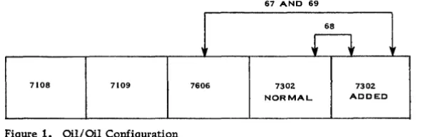
Configuration A ,Oil/Oil
In this configuration, the units must be placed as shown in Figure 1.
67 AND 69
68
n
7108 7109 7606 7302 7302
NORMAL ADDED
Figure 1. Oil/ Oil Configuration
In this system, the two storage units are butted together and the signal cables ar~ of fixed length and need not be specified with the feature order.
Configuration B , Oil/Air
In this configuration, the units are placed as shown in Figure 2.
7302A (ADDED)
72 AND 70 ~
I
~
,
717108 7109 7606 7302
(NORMAL)
Figure 2. Oil/ Air Configuration
[image:11.615.75.387.315.411.2] [image:11.615.81.449.489.625.2]Configuration C, Air/Air
In this configuration the units must be placed as shown in Figure 3.
7302A 7302A
NORMAL ADDED
~ 71
t
I72 AND 70
+
7108 7109 7606
Figure 3. Air/ Air Configuration
In this system, the normal 7302 would be an air-cooled unit and would be placed within the cable restrictions of a normal 32K system.
The added 7302 may be placed as the physical planner desires within the cable length restrictions noted in Cable Chart C. (Normal system cables are not shown.)
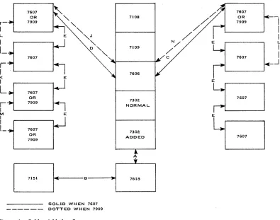
All other new cables to be added to the system are shown in Figure 4 and listed on Chart D. r -I L K I
L
r
I M I Il_
7607 OR 7909 OR 7909 E E E 7302 NORMAL 7302 ADDED~
__ 7_1_5_1 __~~IC~----_B---~'~
___
7_6_1_8 _ _~
SOLID WHEN 7607- - - DOTTED WHEN 7909
Figure 4. Cables Added to System
7607 OR
7909
--j
I
I
~
L7607
l
-c-..J
EEJ
[image:12.612.95.475.102.257.2] [image:12.612.106.501.368.679.2]Cable Chart B OilLAir
y Z
Diameter Max. Dimension
Cable Group IBM PIN Description (inches) length (ft) inches Note
70 587314 7606 to 7302 .93 40 60 12
71 a,b 587314 7302 to 7302A .93 40 60 12
72 a 587314 7606 to 7302A .93 40 60 12
I. Included in additional core storage rental. Use dimensions shown to determine total length, and order with the additional core storage.
Cable Chart C Air/Air
y Z
Diameter Max. Dimension
Cable Group IBM PIN Descri ption (inches) length (ft) inches Note
70 587314 7606 to 7302A .93 40 60 12
71 a,b 587314 7302A to 7302A .93 40 12 12
72 a 587314 7606 to 7302A .93 40 60 12
I. Included in additional core storage rental. Use dimensions shown to determine total length, and order with the additional core storage.
Cable Chart D System Cables (Exclusive of 7302 Signal)
Cable Group IBM PIN Descri ption
A 532542 400 cycle to
7302
A 532554 60 cycle to
7302
A 532537 7302 heater
input
B 5303620 7151 to 7618
C 587314 7606 to 7607 #1
D 587314 7606 to 7607 #5
E 587314 7607 to 7607
J 5330620 7606 to 7909
K 5330620 7607 to 7909
L 5330620 7909 to 7607
M 5330621 7909 to 7909
N 5330620 7606 to 7909
Diameter (inches) .70 1.20 .50 .93 .93 .93 .93 .93 .93 .93 .93
y Z
Max. Dimension
length (it) inches Note
75 11 70
75 11 67
75 9 162 I, IV
75 11 12 II, III, IV
50 55 II, III
53 55 II, III
57 55 II
50 24 V
57 24 V
24 55 V
24 24 V
57 24 V
I. Not included in additional core storage feature rental and must be ordered separately with 7302. Use dimensions shown to determine total length.
II. Included in additional core storage rental. Use dimensions shown to determine total length. (Refer to IBM 7090 Data Processing System Physical Planning Installation Manual, Form X22-1209-1.)
IV. This cable not required for configurations Band C.