400
WARNING
VISUAL TECHNOLOGY INCORPORATED, 540 MAIN STREET, TEWKSBURY, MA 01876
VIDEO DISPLAY TERMINAL REFERENCE MANUAL
VISUAL TECHNOLOGY INCORPORATED, 540 MAIN STREET, TEWKSBURY, MA 01876
SAFETY WARNING
Hazardous voltages 115, 220 V AC and 15 KV DC are present when the ,terminal is on, and may remain after power is removed. Use caution when
working on internal circuits, and do not work alone.
When handling the cathode ray tube caution is required as the internal phosphor is toxic. Safety goggles and gloves must be used whenever the CRT tube is handled. Should the tube break, skin or eyes exposed to the phosphor, rinse the affected area with cold water and consult a physician.
This terminal is supplied with a cord set that includes a safety ground. Do not use this terminal with an ungrounded outlet, missing ground pin, or use any adaptor which will defeat the safety ground.
Insure that power is turned off before connecting or disconnecting the keyboard cable.
PREFACE
This manual describes the features and operation of the VISUAL 400 display terminal. Programming and application information together with first level service information is also included. For second level mainte-nance information, please consult the VISUAL 100/400 Maintemainte-nance Manual.
VISUAL TECHNOLOGY INCORPORATED, 540 MAIN STREET, TEWKSBURY, MA 01876
TABLE OF CONTENTS
1. INTRODUCTION ... . 1.1 COMMONLY USED TERMS ... .
2. SPECIFICATIONS/CHARACTERISTICS ... . 2.1 KEYBOARD ... . 2.2 VIDEO MONITOR AND COMPOSITE VIDEO ... . 2.3 P.C.B. AND COMMUNICATION INTERFACE ... . 2.4 GENERAL SPECI FICATIONS ... .
3. START-UP PROCEDURES ... . 3.1 INSTALLATION ... . 3.2 SET-UP MODES ... . 3.2.1 General ... . 3.2.1.1 How to Enter SET-UP MODE' ... . 3.2.1.2 How to Determine the Status of SET-UP Features ... . 3.2.1.3 How to Change SET-UP Features ... . 3.2.1.4 Performing a RECALL Operation . ~ ... . 3.2.1.5 Performing a SAVE Operation ... . 3.2.1.6 Performing a RESET Operation ... . 3.2.2 SET-UP Feature Definitions ... . 3.2.2.1 Line/Local ... . 3.2.2.2 Column Mode ... . 3.2.2.3 Tabs ... . 3.2.2.4 Screen Brightness ... . 3.2.2.5 Scrolling Mode ... . 3.2.2.6 Autorepeat Mode ... . 3.2.2.7 Screen Mode ... . 3.2.2.8 Cursor Selection ...•.. 3.2.2.9 Margin Bell ... . 3.2.2.10 Keyclick ... . 3.2.2.11 Transmitter XON/XOFF ... . 3.2.2.12 ReceiverXON/XOFF ... . 3.2.2.13 Line Transmit Mode ... . 3.2.2.14 Autowrap Mode ... . 3.2.2.15 Linefeed New Line Mode ... . 3.2.2.16 Auto Tab Mode ... , ... . 3.2.2.17 Parity Enable ... ' ... . 3.2.2.18 Parity Sense ... : ... . 3.2.2.19 Bits Per Character ... . 3.2.2.20 Refresh Rate ... . 3.2.2.21 Duplex ... . 3.2.2.22 Local Echo ... . 3.2.2.23 Turn Around ... .
VISUAL TECHNOLOGY INCORPORATED, 540 MAIN STREET, TEWKSBURY, MA 01876
TABLE OF CONTENTS - Continued
Page
3.2.2.24 Character/Block Mode ... . 21
3.2.2.25 Control Representation Mode ... . 21
3.2.2.26 Erasure Mode ... . 21
3.2.2.27 Vertic Ie Editing Mode ... . 21
3.2.2.28 Horizontal Editing Mode ... . 21
3.2.2.29 Edit Boundary Mode ... . 21
3.2.2.30 Select Editing Extent Mode ... . 21
3.2.2.31 . Guarded Area Transfer Mode ... . 22
3.2.2.32 Transmit Request Mode ... . 22
3.2.2.33 Multiple Area Transfer Mode ... . 22
3.2.2.34 Transfer Termination Mode ... . 22
3.2.2.35 Modified Data Area Transfer Mode ... . 22
3.2.2.36 Page Transfer Mode ... . 22
3.2.2.37 Xmit Speed ... . 22
3.2.2.38 Receive Speed ... . ;,,~> 22 3.2.2.39 Answerback Message ... . 22
3.2.2.40 Select Keyboard layout ... . 23
3.2.2.41 Start of Message Code (SaM) ... . 24
3.2.2.42 Area Separator Code (AS) ... . 24
3.2.2.43 First and Second End of Line Codes (FEOl & SEOl) ... . 24
3.2.2.44 First and Second End of Message Codes (FEOM & SEOM) .. 25
3.2.2.45 Turn Around Control Code (TACC) ... . 25
4. KEYBOARD CONTROLS AND l.E.D.'S ... ~ ... . 27
5. TERMINAL PROGRAMMING ... . 33
5.1 GENERAL ... . 33
5.2 CONTROL CODES ... . 34
5.3 CONTROL SEQUENCE FUNCTIONS ... . 34
5.3.1 Scrolling Region Command ... . 35
5.3.2 Cursor Movement Commands ... . 35
5.3.3 Tabbing Commands ... . 37
5.3.4 Erasure Commands ... . 39
5.3.5 Character Size and Screen Alignment Commands ... . 41
5.3.6 Program Function Key Command ... . 41
5.3.7 Program lED Command ... . 42
5.3.8 Save/Restore Cursor Commands ... . 42
5.3.9 Report Commands and Responses ... . 42
5.3.10 Test Command ... . 43
5.3.11 Character Set Commands ... . 44
5.3.12 Editing Commands ... . 44
5.3.13 Set Commu nication Control Codes Command ... . 47
VISUAL TECHNOLOGY INCORPORATED, 540 MAIN STREET, TEWKSBURY, MA 01876
TABLE OF CONTENTS - Continued
Page
5.3.14 Video Attribute Command. . . 48
5.3.15 Remote Transmit Command ... 48
5.3.16 Reset Command . . . 48
5.3.17 Define Area Qualification Command ... 48
5.3.18 Clear Attribute Code Command . . . 51
5.4 MODES (SET/RESET) . . . 53
5.4.1 Guarded Area Transfer Mode . . . 55
5.4.2 Keyboard Action Mode ... 56
5.4.3 Control Representation Mode ... 56
5.4.4 Insert Replace Mode. . . 56
5.4.5 Erasure Mode. . . 56
5.4.6 Vertic Ie Editing Mode ... 57
5.4.7 Horizontal Editing Mode ... 57
5.4.8 Character Mode ... 57
5.4.9 Multiple Area Transfer Mode ... . . 57
5.4.10 Transfer Termination Mode. . . .. . . 58
5.4.11 Linefeed New Line Mode . . . 58
5.4.12 Protect Mode... . 58
5.4.13 Autotab Mode ... 58
5.4.14 Modified Data Area Transfer Mode ... 58
5.4.15 Column Mode. . . 59
5.4.16 Scrolling Mode. . . 59
5.4.17 Screen Mode. . . 59
5.4.18 Origin Mode . . . 60
5.4.19 Autowrap Mode . . . 60
5.4.20 Autorepeat Mode. . . 60
5.4.21 Transmit Request Mode. . . 60
5.4.22 Line Transmit Mode. . . 60
5.5 SELECT EDITING EXTENT MODE. . . 60
6. DATA TRANSMISSION ... 63
6.1 MODES ... 63
6.2 MESSAGE FRAMING. . . .. . . 63
6.2.1 Block Mode Transmissions . . . 65
6.2.2 Function Key, Answerback and Status Transmissions ... 66
6.2.3 Line Drawing and Foreign Characters. . . . 66
6.3 HALF/FULL-DUPLEX ... :... 68
6.3.1 Half-Duplex... . . . 68
6.3.2 Full-Duplex... 68
VISUAL TECHNOLOGY INCORPORATED, 540 MAIN STREET, TEWKSBURY, MA 01876
TABLE OF CONTENTS - Continued
Page
7.2 SET-UP P FEATURE DEFINITIONS ... 74
7.2.1 Copy Mode... ... 74
7.2.2 Printer Controller Mode . . . 74
7.2.3 Auto Print Mode ... 74
7.2.4 Underline Sequence. . . 74
7.2.5 Printer Busy . . . 74
7.2.6 Printer Type. . . 75
7.2.7 LF Suppress . . . 75
7.2.8 Cancel Select ... 75
7.2.9 Parity Select and parity Enable ... 75
7.2.10 Bits per Character ... " . ... . .. . .. . . . 76
7.2.11 Busy Polarity. . . 76
7.2.12 Print Speed. . . . 76
7.3 PRINTER COMMANDS AND MODES. . . .. . . 76
7.3.1 Print Line/Page Commands ... 76
7.3.2 Copy Mode. . . 76
7.3.3 Printer Controller Mode . . . 77
7.3.4 Auto Print Mode ... 77
8 PAGING OPTION ... 81
8.1 GENERAL... 81
8.2 MEMORY ORGANIZATION ... ,. . . .. 81
8.3 ADDITIONAL MODES. . . 85
8.3.1 Edit Boundary Mode ... 85
8.3.2 Page Transfer Mode ... 85
8.4 ADDITIONAL COMMANDS. . . 87
8.4.1 Scroll Up ... 87
8.4.2 Scroll Down . . . 87
8.4.3 Next Page. . . . 87
8.4.4 Previous Page ... 88
8.4.5 Print All . . . 88
8.5 ADDITIONAL KEYBOARD CONTROLS. . . 88
8.6 MODIFIED COMMAND OPERATIONS. . . ... . .. . . .. . ... . . .. . 88
8.6.1 Absolute Cursor Positioning. . . 88
8.6.2 Horizontal and Vertic Ie Position ... 88
8.6.3 Form Feed .. . . 88
8.6.4 What is Cursor Location Relative to Screen? ... ;... 88
8.6.5 What is Cursor Location Relative to Entire Memory? . . . 90
8.7 RECEIVING DATA. . . 90
8.8 OPERATION RESTRICTIONS. . . .. .. . . 90
9. FIRST LEVEL MAINTENANCE. ... . ... ... .. . .. . . .. . . 91
9.1 GENE RAL ... '. . . . 91
VISUAL TECHNOLOGY INCORPORATED, 540 MAIN STREET, TEWKSBURY, MA 01876
TABLE OF CONTENTS - Continued
Page
9.2 REAR PANEL. . . .. . ... . .. . . .... .. .. .. . . .. . .. . .. . . ... .. .. . 91
9.2.1 Rear Panel Removal .... . . 91
9.2.2 Rear Panel Installation . . . 91
9.3 TOP COVER ... 92
9.3.1 Top Cover Removal ... . 92
9.3.2 Top Cover Installation ... 92
9.4 PRINTED CIRCUIT BOARD REMOVAL AND INSTALLATION... . 92
9.5 TV MONITOR PCB REMOVAL AND INSTALLATION. . . ... . 93
9.6 CRT AND FLYBACK REMOVAL AND INSTALLATION... 93
9.7 TV MONITOR ADJUSTMENTS ... 93
9.8 110/220 VOLT SELECTION. . . . 95
9.9 TROUBLESHOOTING ... 96
9.9.1 Self Test. . . 96
9.9.2 Fault Isolation. . . 96
APPENDIX I - VISUAL 400 CONTROL SEQUENCE SUMMARY. . . 99
APPENDIX II - GRAPHIC RENDITION OF CONTROL CODES ... 105
APPENDIX 111- KEYBOARD LEGENDS AND CHARACTER SETS. .. . . ... . .. 107
APPENDIX IV - TURN-AROUND CONNECTOR FOR INTERFACE TESTS ... 115
Figure 2-1 Figure 3-1 Figure 3-2A Figure 3-2B Figure 3-3 Figure 3-4 Figure 3-5 Figure 4-1 Figure 7-1 Figure 7-2 Figure 8-1 Figure 9-1 Figure 9-2 Figure 9-3 Figure 9-4 Table 2-1 Table 2-2 Table 3-1 Table 4-1 Table 4-2 Table 4-3 Table 4-4 Table 5-1 Table 5-2 Table 5-3 Table 5-4 Table 5-5 Table 5-6 Table 5-7 Table 5-8 Table 5-9 Table 6-1 Table 7-1 Table 7-2 Table 8-1 Table 8-2 Table 8-3 Table 8-4
VISUAL TECHNOLOGY INCORPORATED, 540 MAIN STREET, TEWKSBURY, MA 01876
LIST OF FIGURES
Byte Configurations ... . SET-UP A Presentation ... . SET-UP B Presentation ... . SET-UP B Presentation, Paging Option ... . SET-UP B Summary ... . SET-UP C Presentation ... . SET-UP C Summary ... ; ... . VISUAL 400 Keyboard Layout ... . SET-UP P Presentation ... . SET-UP P Summary ... . Paging Memory Organization ... . Rear Panel Screw Locations ... . Top Cover Removal ... . Location of TV Monitor Adjustments ... . 110/220 V Section ... .
LIST OF TABLES
EIA RS232-C Signal Definitions and Connector Piris and 20 MA
Current Loop Pin Polarity Designations ... . I nitial Settings and Functions for I nternal Switches ... . SET-UP Feature Change Summary ... . Codes Generated by Cursor Positioning Keys ... . FUNCTION Key Summary ... . Default Values of Function Keys ... . LED Summary ... . Control Code Summary ... . Incremental Cursor Positioning Commands ... . Selective Parameters Associated with "Report Terminal Parameters" Response ... . Line Drawing Character Set ... . Selective Parameters Associated with Video Attribute Command .... . Selective Parameters Associated with Define Area Qualification
Command ... . Selective Parameters Associated with Clear Attribute Code Command .. Selective Parameters Associated with Set/Reset Mode Control
Sequences ... . Selective Parameters Associated with Select Editing Extent Mode .... . Combinations of Transmission Modes ... . Printer Port Pin Designations ... . Summary of Print Commands and Modes ... . Format Effectors which Cause Movement of the Document ... . Editor Functions which Cause Movement of the Document ... . Editor Functions Affected by Edit Boundary Mode ... . Additional Keyboard Controls ... .
viii Page 6 10 11 11 12 13 13 27 72 73 82 91 92 94 95 4
5
15 .
VISUAL TECHNOLOGY INCORPORATED, 540 MAIN STREET, TEWKSBURY, MA 01B76
1. INTRODUCTION
The new VISUAL 400 is a highly sophisticated smart editing video terminal utilizing the Z-80 microprocessor. The VISUAL 400 adheres to the American National Standards Institute (ANSI) X3.64 standard for display terminals, thus making the VISUAL 400 an ideal terminal for designing a lasting and flexible system architecture.
The VISUAL 400 supports both conversational and buffered transmission modes with independent transmit and receive rates up to 19,200 b.p.s. The buffered mode permits the user to locally store information and also allows extensive editing. And editing is not merely limited to the insertion and deletion of lines and characters. The user may define whether data on the screen moves up or down for inserted/deleted lines, and right or left for inserted/deleted characters. Further, the user may limit the extent of editing functions to the current field, line, area, or page, via software selectable modes.
Multiple area definition including numeric only, alpha only, right justify, protect, must fill and total fill ensures accurate, speedy data entry. •
When it comes to transmission, the VISUAL 400 allows all or any part of the screen to be trans-mitted including modified fields only. Message framing is completely user programmable as are the twelve function keys.
Your operator will appreciate the advanced human engineering features of the VISUAL 400 like smooth scrolling of data on the screen, block or underline cursor selection, detached keyboard with n-key rollover and selectable autorepeat. Also a tiltable screen with etched non-glare faceplace available in green or white phosphor. We've eliminated all external switches, except for power ON/O F F, through extensive use of non-volatile memory allowing terminal parameters to be con-figured from the keyboard as desired and the configuration saved for re-use.
1.1 COMMONLY USED TERMS
Control Sequence Introducer
Two codes (ESC [) which introduce all multi-code control sequences.
Pararpeter, Numeric and Selective
Character combinations from Column 3 of the ASCII Code Chart that are used in control sequences. Numeric parameters are abbreviated Pn and usually specify how many times a particular function is to be performed. Selective parameters are abbreviated Ps and usually specify how a particular function is to be performed. The maximum decimal value of either Pn or Ps in 255.
Area Attribute Code - (AAC)
VISUAL TECHNOLOGY INCORPORATED, 540 MAIN STREET, TEWKSBURY, MA 01876
Area
A group of contiguous characters starting with an AAC and ending with the character imme-diately preceding the next AAC, or the end of the screen. An area may extend over many lines or may be a single character with an AAC controlling the data to be entered into the character position. Areas exist in Block mode only and only when Protect mode is set.
Field
A group of contiguous characters starting at a tab stop and end at the next tab stop. A field may contain one or many areas, but never less than one area. Fields exist in Block mode . only.
VISUAL TECHNOLOGY INCORPORATED, 540 MAIN STREET, TEWKSBURY, MA 01876
2. SPECIFICATIONS/CHARACTERISTICS
The VISUAL 400 display terminal consists of three basic subassemblies: Keyboard, Video Monitor, and Printer Circuit Board including communication interface. The following para-graphs summarize the basic features of each subassembly. Section 2.4 lists the general specifications of the VISUAL 400.
2.1 KEYBOARD
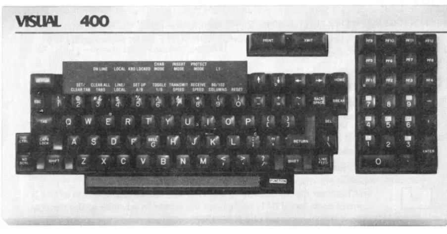
The VISUAL 400 employs a field proven solid-state keyboard using capacitively coupled keys for high reliability and long life. The keys are arranged in a familiar "typewriter" lay-out as pictured in Figure 4-1.
The keyboard is fully detachable from the terminal for operator comfort and optimal space utilization. The cable leading from the keyboard is terminated with a 15-pin connector which plugs into the receptable labeled keyboard on the rear panel.
All keys except those noted in Section 3.2.2.6 may also be defined to be "typomatic", (auto repeat) or non-typomatic. The typomatic feature allows the codes for the depressed key to be generated at a rate of 30 characters per second.
Section 4 details all keys on the keyboard and the code(s) they generate.
2.2 VIDEO MONITOR AND COMPOSITE VIDEO
The Video Monitor used in the VISUAL 400 is a high quality 12" cathode ray tube (CRT). The CRT uses a P4 white phosphor and a non-interlaced raster scanning method to produce crisp, easy to read characters of high resolution. The CRT includes a non-glare faceplate to assure easy readability even in the brightest environments. Characters are formed using 7 x 7 dot matrix for upper case, and 7 x 9 for lower case. The VISUAL 400 also has a CRT saver feature which causes the screen to dim if the terminal is inactive for a period of 8 minutes. Hitting any key on the keyboard will cause the screen to return to normal intensity. This feature greatly prolongs CRT life.
The format for character display may be either 24 lines of 80 characters or 24 lines of 132 characters. Characters may also be formed in double heights and double widths on a line by line basis.
Composite video output is provided via a jack on the rear panel. This feature will drive another T. V. monitor of the following specifications:
1. Video Bandwidth 12 MHz 2. Horizontal Frequency 15.6 kHz
3. Voltage Output 1.5 Volts, Peak to Peak
2.3 P.C.B. AND COMMUNICATION INTERFACE
Pin
1 2 3 4 5 6 7 8 11 12 17 18 19 20 21 23* 25
VISUAL TECHNOLOGY INCORPORATED, 540 MAIN STREET, TEWKSBURY, MA 01876
The VISUAL 400 provides as standard, both an EIA RS232-C and a 20-milliampere current loop interface. Both interfaces conform to a bit-serial, asynchronous, start-stop format and may operate in either a half-duplex or full-duplex mode.
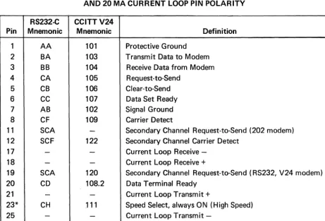
The E IA RS232-C interface provides all control and sequencing signals for interfacing to remote equipment through a modem or for direct connection to local equipment. This interface labeled EIA, is located on the rear panel and interfaces with the communications line via a 25 pin connector. Table 2-1 lists all the EIA signal·definitions and connector pins for the RS232-C interface.
The 20-milliampere current loop interface may be passive or active and allows direct connec-tion to most equipment. Table 2-1 lists the pin polarity designaconnec-tions for the 20-milliampere current loop interface.
TABLE 2-1
EIA RS232-C SIGNAL DEFINITIONS AND CONNECTOR PINS, AND 20 MA CURRENT LOOP PIN POLARITY
RS232-C CCITTV24
Mnemonic Mnemonic Definition
AA 101 Protective Ground
BA 103 Transmit Data to Modem
BB 104 Receive Data from Modem
CA 105 Request-to-Send
CB 106 Clear-to-Send
CC 107 Data Set Ready
AB 102 Signal Ground
CF 109 Carrier Detect
SCA
-
Secondary Channel Request-to-Send (202 modem) SCF 122 Secondary Channel Carrier Detect-
-
Current Loop Receive--
- Current Loop Receive +SCA 120 Secondary Channel Request-to-Send (RS232, V24 modem) CD 108.2 Data Terminal Ready
-
- Current Loop Transmit +CH .111 Speed Select, always ON (High Speed)
-
- Current LoopTransmit-*Pin 23 is used on some dual-speed modems to select speed. This VISUAL 400 always has this signal ON. If low speed operation of the dual-speed modem is desired, it is necessary to "float" pin 23 (extract pin 23 from the modem cable at one end).
VISUAL TECHNOLOGY INCORPORATED, 540 MAIN STREET, TEWKSBURY, MA 01876
The EIA RS232-C or 20-milliampere current loop interface is selected via a row of 8minia-ture dip switches located at position U73 on the P.C.B. Table 2-2 summarizes the initial switch setting and the function of each miniature switch.
TABLE 2-2
INITIAL SETTINGS AND FUNCTIONS FOR INTERNAL SWITCHES
Switch Initial
.
Number Setting OFF ON Comments
1 OFF Disable Optional Enable Optional No Optional
Character Generator Character Generator ROM in
ROM ROM Standard Unit
2 OFF E I A Interface Cu rrent Loop Interface
3 OFF EIA Interface or Cu rrent Loop Receive
Cu rrent Loop I nterface Passive Active
4 OFF Passive Cu rrent Active Cu rrent Receive
Loop Interface Loop Interface (Exterior Current (V400 Current
Source) Source)
5 OFF EIA Interface or Cu rrent Loop X-mit
Current Loop I nterface Passive Active
6
OFF Passive Current Active Current X-mitLoop Interface Loop Interface
7 OFF Pin #19 on EIA Pin #19 Switches For EIA
Interface Appropriately Secondary
Disconnected Channel
8 ON Pin #11 on EIA Pin #11 Switches For Bell 202
Interface Appropriately Secondary
Disconnected Channel
Examples of Typical Settings
1. Passive Current Loop Interface; Switches 2, 3,5 ON 2. Active Current Loop Interface; Switches 2, 4, 6 ON
VISUAL TECHNOLOGY INCORPORATED, 540 MAIN STREET, TEWKSBURY, MA 01876
Other communication interface features include:
• Local copy capability for applications requiring the "echoing" of transmitted data (see Section 3.2.2.21)
• 16 data rates ranging from 50 to 19,200 baud • I ndependent transmit/receive rates
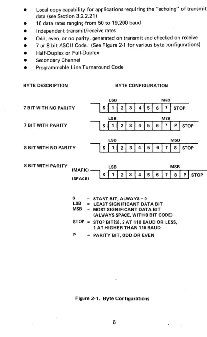
• Odd, even, or no parity, generated on transmit and checked on receive • 7 or 8 bit ASCII Code. (See Figure 2-1 for various byte configurations)
• Half-Duplex or Full-Duplex
• Secondary Channel
• Programmable Line Turnaround Code
BYTE DESCRIPTION BYTE CONFIGURATION
LSB MSB
7 BIT WITH NO PARITY
I
S111
II
2II
3 il\ 4II
5:1 61
7I
STOPLSB, MSB
7 BIT WITH PARITY
LSB MSB
8 BIT WITH NO PARITY
8 BIT WITH PARITY LSB MSB
(MARK)I~
(SPACE). S
,I,
II
211
3II
4I
5il6
I
7\ 81\pi
STOPS STARTBIT,ALWAYS=O
LSB LEAST SIGNIFICANT DATA BIT MSB MOST SIGNIFICANT DATA BIT
(ALWAYS SPACE, WITH 8 BIT CODE) STOP STOP BIT(S), 2 AT
110
BAUD OR LESS,1 AT HIGHER THAN
110
BAUD P PARITY BIT, ODDOR EVENFigure 2-1. Byte Configurations
VISUAL TECHNOLOGY INCORPORATED, 540 MAIN STREET, TEWKSBURY, MA 01876
2.4 GENERAL SPECIFICATIONS
TERMINAL TYPE:
COMMUNICATION
Code: Type:
Speed:
Method:
Mode: Parity:
Interface:
Stop Bits:
SCREEN PRESENTATION
Display Unit:
Format:
Cursor:
ANSI X3.64 Standard, TTY Compatible Z-80 Microprocessor based.
128 Character ASCII Serial Asynchronous
Independent Xmit/receive rates; 50,75, 110 134.5,150,200,300,600,1200,1800,2000 2400,3600,4800,9600,19,200
Character by Character (conversational) or Block Full-duplex with or without local echo, or Half-duplex
Odd, even, none
E IA RS232-C and 20/50 M.A. current loop
2 at 110 BPS or below, 1 at 134.5 BPS and above
12" non-glare CRT. Composite video output
24 lines by 80 columns, or 24 lines by 132 columns
Blinking block or blinking underline, selectable
Character Formation: 7 x 7 dot matrix with 2 dot lower-case extenders
Character Presentation:
Refresh Rate:
Character Sets:
Video Attributes:
Multiple Area Definition:
DATA ENTRY:
Single/double heights and widths, selectable on line basis
50/60 Hz
128 ASCII, German, Swedish/Finnish, Norwegian/Danish, French, U.K., Spanish, Portuguese; plus 32 character graphics all standard
Underline, reverse-video, blink, bold in any combination
Numeric only, alpha only, alph-numeric, right justify, must fill, total fill, protect, protect and guard
Scroll mode, selectable scroll area, smooth scroll.
AUDIBLE INDICATORS; On receipt of BEL code, keyclick for xmitted codes and error indicator, selectable bell at column 72/124.
EXTERNAL OPERATOR
CONTROLS: Power ON/OFF
VISUAL TECHNOLOGY INCORPORATED, 540 MAIN STREET, TEWKSBURY, MA 01876
KEYBOARD:
DIAGNOSTICS:
POWER:
PHYSICAL:
OPERATING RANGE:
OPTIONS:
STANDARDS:
Detachable sol id-state, capacitive scan technology, selectable auto repeat.
Self test
117 x AC ± 15% @ 1 A, 250 V AC ± 15% @ .5A
H x W x D; 13" x 17" x 21", weight: Keyboard 6 Ibs, Terminal 37 Ibs.
10 to 40 degrees Celsius, -20 to 60 (storage) Humidity 5% to 95% non-condensing
Serial Buffered Printer Interface Green Phosphor Screen
2 or 4 Extra Pages of Memory
Listed U.L. 478 File E73056
VISUAL TECHNOLOGY INCORPORATED, 540 MAIN STREET, TEWKSBURY, MA 01876
3. START-UP PROCEDURES
3.1 INSTALLATION
When installing the VISUAL 400 for the first time, or when moving the terminal to a new location or new communications trunk, the following steps should be followed.
1. Unpack the terminal and place it in the desired work area.
2. Tilt the terminal portion up and read the voltage value from the serial number tag. If the voltage is correct, proceed to step 4.
3. If the voltage is incorrect, change the transformer wiring as described in Section 8.8.
4. If the interface is EIA, proceed with step 7.
5. If the interface is current loop, remove the rear panel (Section 8.2) and set the internal switches as defined in Table 2-2.
6. Install the rear panel.
7. Plug in the Keyboard cable, Interface cable, and Printer cable into the corre-sponding connector.
8. Power on the terminal.
9. If intensity is too low, cursor not visible, press SET-UP key once, then press and
hold the
[£J
key until the screen presentation is visible.10. Proceed with SET-UP procedure as described in Section 3.2.
3.2 SET-UP MODES
3.2.1 General
The VISUAL 400 does not use exterior switches or jumpers to determine which built-in ter-minal features will be on or off. Instead, a nonvolative RAM memory is used to remember which features and modes are enabled and disabled. Terminal features and modes are selected and stored in a special mode called SET-UP mode. When SET-UP mode is entered, the status of terminal features is displayed on the screen. You can then change the terminal features to any desired configuration. Once the desired configuration is selected, the termi-nal will function per the new configuration on either temporary basis (by exiting SET-UP mode) or fixed basis (by performing the SAVE operation).
SET-UP mode is divided into three parts; SET-UP A, SET-UP B and SET-UP C*.SET-UP A shows whether an 80 or 132 column screen format is selected and also displays the location of each columnar tab stop. Each SET-UP A feature is described in detail in Section 3.2.2. SET-UP B and SET-UP C summarize the status of other terminal features and are also described in detail in Section 3.2.2. Table 3-1 summarizes the various features that are determined in SET-UP A, B, and C.
VISUAL TECHNOLOGY INCORPORATED, 540 MAIN STREET, TEWKSBURY, MA 01876
3.2.1.1 How to Enter SET-UP Mode
SET-UP A is entered by depressing the SET-UP key on the keyboard. SET-UP 8 may only be entered from SET-UP A and SET-UP C may only be entered from SET-UP 8 and are
entered by depressing the
I
~·I
key on the keyboard.Subsequent depressions of the
rn
key will alternately switch between UP A,SET-UP 8 and SET-SET-UP C.
3.2.1.2 How to Determine the Status of SET-UP Features
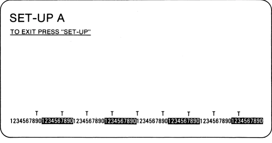
When SET-UP A is entered, the screen will display a presentation as shown in Figure 3-1. This presentation shows the location of each tab stop, as indicated by a "T" and also shows whether an 80 column or 132 column format is enabled.
SET-UP A
TO EXIT PRESS "SET-UP"
T
T
T
T
T
T
T
T
T
123456789ot.JU1:rI:pnn 2345678901tJU11J:pnn 2345678901.JU1:rI:pnn 234567890l
Nf.:W::I:w:1tpr:::ll1l:1CiI:r.l:r.'Iplr:t11
Figure 3-1. SET-UP A Presentation
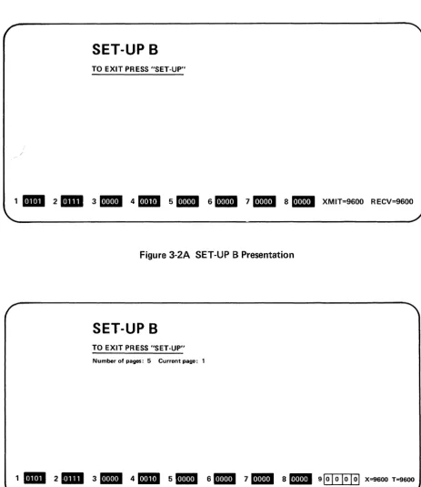
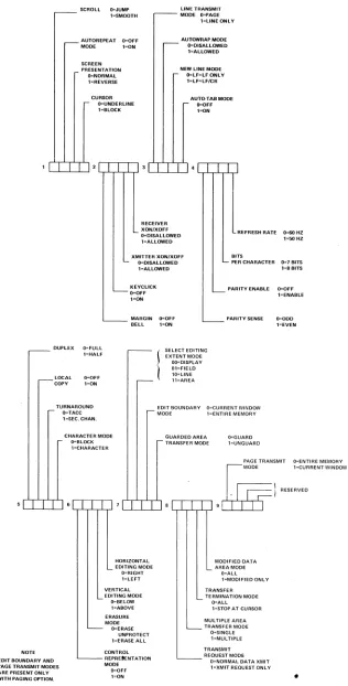
When SET-UP 8 is entered, the screen will display a presentation as shown in Figure 3-2A. This presentation shows which features are enabled per the summary in Figure 3-3.
If the Paging Option is installed, the SET-UP 8 presentation will be altered slightly as indicated in Figure 3.28.
VISUAL TECHNOLOGY INCORPORATED, 540 MAIN STREET, TEWKSBURY, MA 01876
SET-UP B
TO EXIT PRESS "SET-UP"
1
II1II
2mill
3DID
4mD
5m!II
6.l!1!m711!11
8DID
XMIT=9600 RECV=9600Figure 3-2A SET-UP B Presentation
SET-UP B
TO EXIT PRESS "SET-UP"
Number of pages: 5 Current page: 1
1
II1II
2mill
3DB
4mD
5BI
6DB
711!11
8DB
910I
01 0 101 X=9600 T=9600VISUAL TECHNOLOGY INCORPORATED, 540 MAIN STREET, TEWKSBURY, MA 01876
~SCROlL O=JUMP
l"'SMOOTH
r - -AUTOREPEAT O=OFF MODE 1=ON
SCREEN
PRESENTATION O"NORMAL lzREVER8E
r-CU:~~:DERLINE
l=BLOCK
LINE TRANSMIT
r - -MODE O=PAGE
l=LlNE ONLY
_ AUTOWRAP.MODE
.--- O=DISAlLOWED l=ALLOWED NEW LINE MODE
O=LF=LF ONLY
l=LF=lF/CR
AUTO-T AS MODE r- O=OFF
.-oN
dT rTldT f Tl 31 I I II.rTTTl
RECEIVER XON/XOFF
O=DISALLOWED 1=ALLOWED
REFRESH RATE 0=60 HZ 1=50 HZ
XMITTER XON/XOFF
L-. O=DlSAllOWED l=AlLOWED
L - -~6FC~ICK
l=ON
~ MARGIN O=OFF
BELL 1=ON
BITS
L PER CHARACTER 0=-7 BITS 1=8 BITS
L -PARITV ENABLE
L -PARITV SENSE O=OFF l=ENABLE
0=000 l=EVEN
. - - - DUPLEX O=fULL
1;HALF SELECT EDITING EXTENT MODE OO=DlSPI,..AY 01=FIELD 10=lINE 11=AREA r--LOCAl COPY O=OFF l=ON
, - TURNAROUND O=TACC l=SEC. CHAN. CHARACTER MODE D='BLOCK l=CHARACTER Q=GUARD l=UNGUARD
PAGE TRANSMIT O=ENTIRE MEMORV
, 1 RESERVED
51 I rTl0L,-L-,--L,...L,..J7If T T 1.1 I I I I 9
b@
oDE1=CURRENTWINDOWNOTE EDIT BOUNDARY AND PAGE TRANSMIT MODES
ARE PRESENT ONLY
WITH PAGING OPTION.
HORIZONTAL EDITING MODE
O=RIGHT l=LEFT VERTICAL EDITING MODE
():BELOW l=ABOVE ERASURE MODE Q=ERASE UNPROTECT l=ERASE ALL CONTROL REPRE'ENTATION MODE Q=OFF l=ON
MODIFIED DATA L AREA MODE
Q=ALL l=MODIFIED ONL V TRANSFER
L-TERMINATION MODE O=ALL l=STOPAT CURSOR MULTIPLE AREA L -TR~=~~~6~EMODE
l=MUL TIPLE TRANSMIT L - - - -REQUEST MODE
O=NORMAL DATA XMIT l=XMIT REQUEST ONL V
Figure 3-3. SET-UP B Summary
12
VISUAL TECHNOLOGY INCORPORATED, 540 MAIN STREET, TEWKSBURY, MA 01876
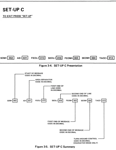
When SET-UP C is entered, the screen will display a presentation as shown in Figure 3-4. This presentation is summarized in Figure 3-5.
SET-UP C
TO EXIT P~ESS "SET-UP"
SOM=I 0021 AS=[Qll] FEol=10131 SEOl=1 ,010
I
FEOM=10031 SEOM=I 0041TACC=~
Figure 3-4. SET-UP C Presentation
,.--_ _ START OF MESSAGE CODE IN DECIMAL
SOM= 002 AS= 031
AREA SEPARATOR CODE IN DECIMAL
FEOL= 013
FIRST END OF LINE CODE IN DECIMAL
SECOND END OF LINE
r---
CODE IN DECIMALSEOL=~
FEOM= 003 SEOM= 004 TACC= 013FIRST END OF MESSAGE CODE IN DECIMAL
SECOND END OF MESSAGE CODE IN DECIMAL
TURN AROUND CONTROL CODE IN DECIMAL (CHARACTER MODE ONL YI
VISUAL TECHNOLOGY INCORPORATED, 540 MAIN STREET, TEWKSBURY, MA 01876
3.2.1.3 How to Change SET-UP Features
As noted earlier in this section, SET-UP features may be stored in non-volatile memory. The SET-UP features stored when the VISUAL 400 is shipped from the factory are shown in Figures 3-1, 3-2 and 3-4.
To change any or all of the SET-UP features from the keyboard, the following procedure should be followed:
1. Enter SET-UP mode by depressing the SET-UP key.
2.
Select either SET-UP A, SET-UPB
or SET-UP C by depressing theI
~
I
key onthe keyboard. SET-UP A must be selected to change SET-UP A features, SET-UP
B to change SET-UP B features and SET-UP C to change SET-UP C features.
Table 3-1 lists the features that are changeable in SET-UP A, SET-UP B and
SET-UP C.
3. Position the cursor (via the
I --I
EJ
spacebar, tab or return key) overthe feature or tab stop to be changed. (Some features may be changed by depress-ing a sdepress-ingle dedicated key and thus do not required this step.)
4. Depress the
I
~
I
key to change the feature under the cursor. SET-UP Bfea-tures have two possible states, enabled or disabled, and each depression of the
I
~I
key will alternately enable and disable the SET-UP B feature under whichthe cursor resides. SET-UP C features have 128 possible states (one for each
ASCII code) and each depression ofthe
I
~
I
key will step through the 128possible states until the desired one is reached.
By following the steps listed in Section 3.2.1.3., SET-UP features may be changed
to suit the preference of a particular operator, and to achieve terminal compati-bility with the host computer.
After changing any or all of the SET-UP features, and exiting SET-UP mode, the VISUAL 400 will function per the new configuration. Please note that the new configuration of UP features is selected on a temporary basis only. The SET-UP features initially displayed are still stored in the non-volatile RAM memory and are remembered by the terminal. The VISUAL 400 will recall and function per this fixed configuration when: the terminal is reset, the terminal is powered-down then powered-up, or a RECALL operation is performed. (See Section 3.2.1.4 for a discussion of the RECAL L operation, see Section 3.2.1.6 for a dis-cussion of the RESET operation.)
If, after changing SET-UP features, it is desired to store the new SET-UP config-uration, a SAVE operation must be performed. (See Section 3.2.1.5 for a discus-sion of the SAVE operation.)
VISUAL TECHNOLOGY INCORPORATED, 540 MAIN STREET, TEWKSBURY, MA 01876 SET-UP Feature Line/Local Column Mode (80/132) Tabs
Screen Brightness
Scrolling Mode (Jump/Smooth)
Autorepeat Mode
Screen Mode
Cursor Selection
Margin Bell
Keyclick Transmitter XON/XOFF Receiver XON/XOFF Line Transmit Mode Autowrap Mode
LF New Line Mode
Auto-Tab Mode
Parity Sense
Parity Enable
Bits Per Character
Refresh Rate
uuplex
Local Echo
Turnaround
Character/Block Mode
TABLE 3-1
SE~UPFEATURECHANGESUMMARY
Change In How to Change Feature
Position Cursor
Dedicated Then Depress SET-UP A SET-UP B SET-UP C Key
I
~
I
Keyvi
vi
V
CD
vi
IT]
vi
rn~
2 and 3vi
vi
y'
0
andGJ
vi
vi
vi
.J
vi
v'
vi
vi
vi
vi
vi
.j
vi
vi
vi
vi
vi
vi
y'
V
vi
vi
vi
vi
vi
vi
vi
vi
vi
vi
vi
vi
v'
vi
vi
.J
.J
vi
vi
y'
VISUAL TECHNOLOGY INCORPORATED, 540 MAIN STREET, TEWKSBURY, MA 01876
TABLE 3-1
SET-UP FEATURE CHANGE SUMMARY (Cont.)
Change In How to Change Feature Position Cursor SET-UP Dedicated Then Depress From Feature SET-UP A SET-UP B SET-UP C Key
IT]
Key Host ControlRepresentation
..;
..;
..;
ModeErasure Mode
..;
..;
..;
VerticalEditing Mode
..;
..;
..;
HorizontalEditing Mode
..;
..;
..;
Select Editing Mode..;
..;
..;
Edit Boundry Mode..;
..;
..;
(Paging Option Only) Guarded Area
Transfer Mode
..;
..;
..;
TransmitRequest Mode
..;
..;
..;
Multiple Area..;
..;
..;
Transfer Mode Transfer
Termination Mode
..;
..;
..;
Modified AreaTransfer Mode
..;
..;
..;
Page Transmit Mode..;
..;
..;
(Paging Option Only)
Transmit Speed
..;
rn
Receive Speed..;
GJ
Answerback
Message
..;
80
Keyboard Layout
..;
60
Start of
Message Code
..;
..;
..;
Area Separator..;
..;
Code
..;
First End of
'Line Code
..;
..;
..;
Second End of
Line Code
..;
..;
..;
First End of
Message Code
..;
..;
..;
Second End ofMessage Code
..;
..;
..;
Turn Around /
Control Code
..;
..;
..;
VISUAL TECHNOLOGY INCORPORATED, 540 MAIN STREET, TEWKSBURY, MA 01876
3.2.1.4 Performing a RECALL Operation
The stored SET-UP features may vary from the SET-UP features currently selected. If it is desired to return to the stored features, the RECALL operation should be performed per the following:
1. Enter SET-UP mode
2. Depress the SHIFT and R keys simultaneously. The screen will be cleared. After a few seconds the terminal will return to SET-UP mode.
3.2.1.5 Performing a SAVE Operation
The SA VE operation is used to store all current SET-UP features, and is performed per the following:
1. Enter SET-UP mode
2. Depress the SH I FT and S keys simultaneously. After a few seconds the terminal will return to SET-UP A mode.
After performing the SAVE operation the current SET-UP features will be stored. To select SET-UP features temporarily, do not use the SAVE operation, simply exit SET-UP mode after changing the features.
3.2.1.6 Performing a RESET Operation
The RESET operation has the same effect as powering-down then powering-up the terminal and is used to run the self test and return the SET-UP features to their fixed states. This operation will also clear the screen of any data. The RESET operation is performed per the following:
1. Enter SET-UP mode
2. Depress the
rn
key on the keyboard. The terminal will reset and return to all initialized parameters and fixed SET-UP features.3.2.2 This section describes SET-UP features and the effect of each feature on the VISUAL 400. 3.2.2.1 Line/Local
On-line or local operation may be selected in either SET-UP A, SET-UP 8, or SET-UP C mode by depressing the
rn
key. On-line operation is indicated by the illumination of the ON-LINE LED. When On-line, the terminal may send and receive data from the host computer.VISUAL TECHNOLOGY INCORPORATED, 540 MAIN STREET, TEWKSBURY, MA 01876
\ 3.2.2.2 Coiumn Mode
The VISUAL 400 may display a screen format of either 24 lines of 80 characters, or 24 lines of 132 characters. When changing between the 80/132 column formats, the contents of the screen are destroyed.
Column mode may also be changed by the host, see Section 5.4.15.
NOTE
If double width characters are used, the number of characters per line is halved i.e., a 132 column format used in conjunction with double width characters provides for 66 double-width characters per line.
3.2.2.3 Tabs
In SET-UP A mode, the location of each tab stop is indicated by a "T". All tab stops may
be cleared by depressing the
I
#3£'I
key or tab stops may be cleared i_ndividually. To setor clear a stop on an individual basis, the following procedure should be followed:
1. Position the cursor under the tab stop to be set or cleared.
2. Depress the
I
~
I
key to set/clear the tab stop at the cursor location.Subse-quent depressions of the
I
~
I
key will alternately set/clear the tab stop at the cursor location.Tab stops may also be set and cleared by the host computer, see Section 5.3.3.
NOTE
The tab stops indicated by a "T" apply to Character mode only.
3.2.2.4 Screen Brightness
Screen brightness may be adjusted up or down, in either SET-UP A, Set-Up B, or SET-UP C
mode. Screen brightness is increased by depressing the
~
key, and decreased byde-pressing the
[j],
key.3.2.2.5 Scrolling Mode
Scrolling of data on the screen may take place in one or two ways: smooth or jump scroll.
Jump scroll is the traditional scrolling method whereby lines of data move one line at a time to make room for new I ines of data entered on the screen.
Smooth scroll is a scrolling hlethod whereby lines of data move a scan line at a time to make room for new lines of data entered on the screen. Smooth scroll is a human engineering feature which allows scrolling lines of data to be more easily read by an operator.
Smooth/Jump scroll may also be changed from the host computer, see Section 5.4.16.
VISUAL TECHNOLOGY INCORPORATED. 540 MAIN STREET. TEWKSBURY. MA 01876
3.2.2.6 Autorepeat Mode
When enabled, Autorepeat mode allows each key to generate its code at a rate of 30 times per second, when the key is depressed for more than 0.75 seconds. All keys will be auto-repeating except for ESC, NO SCROLL, TAB, PRINT, HOME, XMIT, BREAK, RETURN and CTR L with any key, when autorepeat is enabled. When autorepeat is disabled, each key will generate its code once per key depression.
Autorepeat mode may also be selected by the host computer, see Section 5.4.20.
3.2.2.7 Screen Mode
When enabled, this mode causes characters to be formed by black dots on a white back-ground. When reset, characters are formed by white dots on a black backback-ground.
Screen mode may also be selected by the host computer, see Section 5.4.17.
3.2.2.8 Cursor Selection
The cursor marks the point where the next character will be entered on the screen and may be defined to be either a blinking block or a blinking underline.
3.2.2.9 Margin Bell
When enabled, this feature allows a warning bell to be sounded when the cursor is eight characters from the end of the current line. When disabled no warning bell will be sounded.
3.2.2.10 Keyclick
When enabled, this feature provides for an audible keyclick tone to be generated by the VISUAL 400 every time a code-generating key is depressed. When disabled, no audible tone will be sounded to indicate the generation of a code by key depression.
3.2.2.11 Transmitter XON/XOFF
This feature allows the VISUAL 400 to automatically generate the XOFF (DC3) and XON (DC1) synchron ization codes to make sure data transmitted from the host computer is not lost. When enabled, the XOFF code will be transmitted when the receive FIFO buffer is al-most full or the NO SCROLL key is depressed.
The XON code will be automatically transmitted to resume host transmission when the receive FIFO buffer is almost empty or the NO SCROLL key is depressed again.
The host computer must respond to XON/XOFF protocol for this feature to be effective.
NOTE
XON/XOF F protocol is not available in half-duplex.
3.2.2.12 Receiver XON/XOFF
VISUAL TECHNOLOGY INCORPORATED, 540 MAIN STREET, TEWKSBURY, MA 01B76
When enabled and the terminal is in Block mode, receipt of the XOFF code will cause the terminal to suspend any transmission in progress. Upon receipt of the XON code, the terminal will resume any transmission that was in progress before XOFF was received. Any suspended block transmission will be completed.
The XON/XOFF codes will never be recognized if preceded by ESC.
3.2.2.13 Line Transmit Mode
This feature determines the power-up state of Line Transmit mode and is described in Section 5.4.22.
3.2.2.14 Autowrap Mode
This feature determines the power-up state of Autowrap mode and is described in Section 5.4.19.
3.2.2.15 Linefeed New Line Mode
This feature determines the power-up state of LF New Line mode and is described in Sec-tion 5.4.11.
3.2.2.16 Auto Tab Mode
This feature determines the state of Auto Tab mode and is described in Section 5.4.13.
3.2.2.17 Parity Enable
The Parity enable feature provides a check for errors in host transmitted data. When this feature is enabled, the VISUAL 400 will check received data for correct parity (odd or even) and generate parity on transmitted data. If a character is received with incorrect parity, a
I :.:-:
I
will be placed on the screen in place of the error character.3.2.2.18 Parity Sense
The Parity Sense feature determines whether an odd or even parity checking scheme will be utilized. If the Parity Enable feature is disabled, the Parity Sense feature will be disregarded.
3.2.2.19 B its Per Ch aracter
This feature determines whether each transmitted character will contain 7 or 8 data bits. When enabled, this feature will cause 8 bit characters to be transmitted with bit #8 (M.S.B.) always set to space (0), When disabled, each transmitted character will contain 7 data bits. See Figure 2-1 for possible byte configurations.
3.2.2.20 Refresh Rate
50 and 60 Hz refresh-rate capability is built into the basic unit and is determined by this feature. When this feature is OFF, 60 Hz is selected, when ON, 50 Hz is selected.
VISUAL TECHNOLOGY INCORPORATED, 540 MAIN STREET, TEWKSBURY, MA 01876
3.2.2.21 Duplex
This feature selects either half-duplex or full-duplex operation. In full-duplex, the Request to Send Lead is always "high" and data may be independently transmitted and received.
In half-duplex, communication is only in one direction at a time, transmitted data is inter-nally echoed back to the screen. The Request to Send Lead is high when a key is typed on the keyboard or the selected Turn Around Control Code is received. See Section 6.3 for a complete discussion of half/full-duplex operation.
3.2.2.22 Local Echo
The Local Echo feature provides for an automatic "echoing" of transmitted data back to the screen. If an echoing of transmitted data is not desired, the terminal is set for half-duplex, or the host computer or modem provides an echo, this feature should be disabled.
3.2.2.23 Turn Around
This feature applies to Character mode half-duplex operation only and determines whether a Turn Around Control Code or secondary channel will be used for line turnaround.
If the Turn Around feature selects a Turn Around Control Code, the Turnaround Control Code may be any ASCII character and may be selected remotely or in SET-UP C mode.
3.2.2.24 Character/Block Mode
This feature determines whether the terminal operates in a Block transmission mode, or a Character transmission mode as described in Section 5.4.8.
3.2.2.25 Control Representation Mode
This feature determines the state of Control Representation mode as described in Section 5.4.3.
3.2.2.26 Erasure Mode
This feature determines the state of Erasure mode as described in Section 5.4.5.
3.2.2.27 Vertical Editing Mode
This feature determines the state of Vertical Editing mode as described in Section 5.4.6.
3.2.2.28 Horizontal Editing Mode
This feature determines the state of Horizontal Editing mode as described in Section 5.4.7.
3.2.2.29 Edit Boundary Mode
This feature is provided only with the Paging Option and determines the power-up state of Edit Boundary mode as described in Section 8.3.1.
3.2.2.30 Select Editing Extend Mode
VISUAL TECHNOLOGY INCORPORATED, 540 MAIN STREET, TEWKSBURY, MA 01876
3.2.2.31 Guarded Area Transfer Mode
This feature determines the state of Guarded Area Transfer Mode as described in Section 5.4.1.
3.2.2.32 Transmit Request Mode
Thisfeature determines the state of Transmit Request Mode as described in Section 5.4.21.
3.2.2.33 Multiple Area Transfer Mode
This feature determines the state of Multiple Area Transfer Mode as described in Section 5.4.9.
3.2.2.34 Transfer Termination Mode
This feature determines the state of Transfer Termination Mode as described in Section 5.4.10.
3.2.2.35 Modified Data Area Transfer Mode
This feature determines the state of Modified Area Transfer Mode as described in Section 5.4.14.
3.2.2.36 Page Transfer Mode
This feature is provided only with the Paging Option and determines the power-up state of Page Transfer mode as described in Section 8.3.2.
3.2.2.37. Xmit Speed
This feature is used to select one of the 16 available transmit baud rates. When in SET-UP B
mode, each depression on the
rn
key will cause the terminal to step through anddis-play the various transmit baud rates until the desired transmit speed is reached.
3.2.2.38 Receive Speed
This feature is used to select one of 16 available receive baud rates. When in SET-UP B
mode, each depression of the
GJ
key will cause the terminal to step through and dis-play the various baud rates until the desired receive speed is reached.3.2.2.39 Answerback Message
The Answerback Message is set in a manner different from other terminal features. The Answerback Message will be automatically sent to the host computer IJPon receipt of the ENQ code, (without affecting the screen), or whenever eTR L-B REAK is depressed. An-swerback is set per the following procedure.
1. Enter SET-UP B mode.
2. Depress the SH I FT and A keys simultaneously. The terminal will display "A=" on the screen.
VISUAL TECHNOLOGY INCORPORATED, 540 MAIN STREET, TEWKSBURY, MA 01876
3. iEnter the message deliminator character. This character will not be part of the Answerback Message and may be any character not used in the Answerback Message.
4. Enter the Answerback Message which may be a maximum of 20 characters long, and may contain any ASCII characters including control codes. If control codes are part of the message, they will be display~d as • when entered.
5. Enter the message deliminator character to end the Answerback Message.
After completing the above steps, the Answerback Message is selected on a temporary basis. The .Answerback Message may be stored on a fixed basis, like any other SET-UP feature, by performing the SAVE operation.
3.2.2.40 Select Keyboard Layout
The Select Keyboard Layout feature allows the user to seJect anyone of
8
keyboard lay-outs. Each keyboard layout is illustrated in Appendix III. This feature is selected per the following.1. Enter SET-UP B mode.
2.
Depress the SH I FT and K keys simultaneo[lsly. The terminal will display "K=" on the screen.3. Enter a numeric character between zero and seven to select the desired keyboard layout.
1 or 0 = U.S./U.K. 2 = French
3
= German4
= Swedish/Finnish5
= Norwegian 6 = Spanish 7 = Portuguese8
DanishAfter completing the above steps the keyboard layout will be selected on a temporary basis only, but may be stored on a fixed basis, like any other SET-UP feature, by perform-ing the SAVE operation.
Please note that the Select Keyboard Layout SET-UP feature defines the keyboard layout only, and does not alter the presently enabled character set. The Select Character Set Command is used for defining the character set. For example, a user desiring a French version VISUAL 400 will select the French character set via the Select Character Set command
and
also define the Keyboard Layout to be French see Section 5.3.11.WARNING
When selecting a keyboard layout the keyboard is
immediately
VISUAL TECHNOLOGY INCORPORATED, 540 MAIN STREET, TEWKSBURY, MA 01876
3.2.2.41 Start of Message Code (SOM)
This code may be defined to be anyone of the 128 ASCII codes. Once defined, the Start of Message code will precede all Block transmissions from the VISUAL 400 including all function key transmissions, and status transmissions. Receipt of the start of Message Code will lock the keyboard.
The start of Message Code may be set in SET-UP C Mode or may be set remotely via the Set Communication Control Code command, see Section 5.3.13. When SET-UP C is entered, the presently selected SOM will be displayed in decimal notation. To
change the SOM, position the cursor under the SOM decimal value and depress the
I
~
I
key. Each depression of theI
~
I
key will cause the SOM value to step through and dis-play the 128 decimal values of the ASCII Code Chart. When the desired SOM value is reached, the terminal will function per the newly selected SOM by exiting SET-UP mode. The SOM may be stored by performing the SAVE operation.3.2.2.42 Area Separator Code (AS)
This code applies to Block Mode only and may be defined to be anyone of the 128 ASCII codes. Once defined, the Area Separator code will be inserted into Block transmission data streams to separate each transmitted area. Received Area Separator codes will be ignored by the terminal so the user should be careful to select an ASCII code that is not used to perform a terminal function.
The Area Separator code may be set in SET-UP C mode or may be set remotely via the SET Communication Control Code command see Section 5.3.13.
The AS is set from the keyboard in a manner similar to the SOM code, i.e., position the cur-sor under the decimal value of the AS then depress the
I
~
I
key until the desired decimal value is reached.3.2.2.43 First End of Line Code (FEOl) and Second End of Line Code (SEOl) These codes apply to Block mode only and each may be defined to be any of the 128 ASCII codes. Once defined, the FEOl and SEOl will be inserted into Block transmission data streams to signify the end of data on each transmitted line. Receipt of the FEOl will cause the Carriage Return function to be performed and is the only code which will do so. Receipt of the SEOl will cause the Line Feed function to be performed and is the only
code which will do so.
For these reasons the user should be careful when selecting the FEOL/SEOL.
The FEOl and SEOl may be set in SET-UP C mode or may be set remotely via the Set Communication Control Code command, see Section 5.3.13.
The FEOl and SEOl are set from the keyboard in a manner similar to all SET-UP C fea-tures i.e., position the cursor under the decimal value of the FEOl or SEOl then depress the
I·~
I
key until the desired decimal value is reached.VISUAL TECHNOLOGY INCORPORATED, 540 MAIN STREET, TEWKSBURY, MA 01876
3.2.2.44 First End of Message Code (FEOM) and Second End of Message Code (SEaM)
Each of these codes apply to Block Mode only and may be defined to be anyone of the 128 ASCII codes. Once defined, the FEOM and SEaM will terminate all Block transmissions from the VISUAL 400 including all Block Mode function key transmissions and status trans-missions. Receipt of either the FEOM and/or SEaM will clear the keyboard lock condition caused by receipt of tile Start of Message code.
The FEOM and SEaM may be set in SET-UP C mode or may be set remotely via the Set Communication Control Code Command see Section 5.3.13.
The FEOM and SEaM are set from the keyboard in a manner similar to all SET-UP C fea-tures, i.e., position the cursor under the decimal value of the FEOM or SEaM then depress
the
I
~
I
key until the desired decimal value is reached. 3.2.2.45 Turn Around Control Code (TACC)This code applies primarily to Character Mode half-duplex operation and may be defined to be anyone of the 128 ASCII codes. The TACC is used to switch the VISUAL 400 from a
receive state (Request to Send Lead on EIA interface is "Iow") to a transmit state (Request to Send is "high") or vice versa. When received by the terminal the TACC will cause the terminal to switch from the receive state to the transmit state. When transmitted by the terminal, the TACC will cause the terminal to switch from transmit state to receive state.
The TACC will also terminate all Character Mode function key transmissions, answerback transmissions, and status transmissions. Receipt of the TACC will also clear the keyboard lock condition caused by receipt of the Start of Message Code.
The TACC may be set in SET-UP C mode or may be set remotely via the Set Communi-cation Control Code command, see Section 5.3.13.
The TACC is set from the keyboard in a manner similar to all SET-UP C features, i.e.,
posi-tion the cursor under the
dec~mal
value of the TACC then depress theI
~
I
key until the desired decimal value is reached.NOTE
VISUAL TECHNOLOGY INCORPORATED, 540 MAIN STREET, TEWKSBURY, MA 01876
4. KEYBOARD CONTROLS AND L.E.D.'S
This section describes the various keys and LED indicators on the VISUAL 400 keyboard and also describes the codes transmitted and effects of each key on the terminal. As noted in Section 3.2.2 .37, the user may define anyone of eight possible keyboard layouts.
When operating in Block mode, most key depressions will cause a local action only, i.e., no codes will be transmitted with each key depressed. For example, depressing alpha keys will cause the alpha characters to be entered into memory and displayed on the screen, no transmission will occur. When operating in Character mode, most key depressions will cause characters to be transmitted as each key is depressed. A local action will occur only if the transmitted code(s) are "echoed" back to the terminal. (Echoing may be accomplished by the modem, host, or by the terminal.) For example, depressing alpha keys will cause the code for each key depressed to be immediately trans-mitted. The transmitted alpha characters will not appear on the screen unless echoed.
The VISUAL 400 US/UK keyboard is illustrated in Figure 4-1.
400
,- ,
PRINT XU,T 1
Figure 4-1. VISUAL 400 US/UK Keyboard Layout
This key is used to alternately enter and exit SET-UP Mode and will cause no codes to be transmitted under any circumstance.
In Character mode, depressing the ESC key causes the terminal to transmit the ESC control code (octal 033). In Block mode the ESC code causes the terminal to interpret the next received character as opposed to displaying it.
VISUAL TECHNOLOGY INCORPORATED, 540 MAIN STREET, TEWKSBURY, MA 01876
~ ~
~
EJ
Example:
The CTR L key does not produce a code by itself. It is depressed in conjunc-tion with other keys to produce the control codes as described in Secconjunc-tion 5.2.
The SHI FT key does not produce a code by itself. When depressed in con-junction with alph-numeric keys, it causes generation of the corresponding upper case alpha code or the code whose symbol appears on the upper part of the key. Two SH I FT keys are on the keyboard for operator convenience.
The CAPS LOCK key does not produce a code when depressed. This key enables the generation of only upper case alpha characters. The numeric and special keys are not affected by the CAPS LOCK key.
The NO SCROLL key alternately transmits the XOFF (DC3) and XON (DC1) control codes, if the Transmitter XON/XOFF feature is enabled. These codes are used to stop/start transmissions from the host computer, provided the host recognizes these codes. If the Transmitter XON/XOFF feature is dis-abled, the NO SCROLL key will transmit no codes.
NOTE
When the Transmitter XON/XOFF feature is enabled, the NO SCROLL key will be synchronized with the use of XON/XOFF codes generated by the terminal.
Host's transmission causes terminal's FIFO buffer to become almost full causing terminal to automatically transmit XOFF.
If the operator now depresses the NO SCROLL key, no XOFF code is sent.
Buffer empties, no XON sent.
Operator depresses NO SCROLL, XON sent.
BACK SPACE
I n Character mode, depressing the TAB key causes transm ission of the HT control code (octal 011) and causes the cursor to advance to the next tab stop if the transmitted code is echoed. In Block mode the cursor will advance to the next tab stop.
In Character mode, depressing the BACKSPACE key causes transmission of the BS control code (octal 010) and causes the cursor to move one position to the left if the transmitted code is echoed. In Block mode, the cursor moves one position to the left.
In Character mode, depressing the RETURN key causes transmission of the CR control code (octal 015), and causes the cursor to move to the first column of the present line if the transmitted code is echoed. If the New
Line feature is enabled, the RETURN key will transmit the CR and LF
VISUAL TECHNOLOGY INCORPORATED, 540 MAIN STREET, TEWKSBURY, MA 01876
control codes, and will cause the cursor to move to the first column of the next line if the transmitted codes are echoed. In Block mode the cursor will move to the first column of the present line or the first column of the next line.
r::;;:;l
In Character mode, depressing the LlNEFEED key causes transmission of the~ LF control code (octal 012) and causes the cursor to move down one line if the transmitted codes are echoed. In Block mode the cursor moves down one line.
)BAEAKI
SPACE BAR
QJGJ
EJG
Depressing the BREAK key causes a 250 millisecond spacing condition on the data-line. Depressing SH I FT-B REAK causes a 3.5 second spacing condition on the data-line and causes the Data Terminal Ready lead to go low for 3.5 seconds. Depressing CTRL-BREAK causes transmission of the Answer-back Message.
Depressing the DELETE key causes the DEL code (octal 177) to be generated. In Character mode, depressing the SPACE BAR causes the SP code (octal 040) to be transmitted, and causes the character at the cursor location to be erased and the cursor advanced one position if the transmitted code is echoed. In Block mode the character at the cursor location will be erased and the cursor advanced one position.
In Character mode, depressing the Home Key causes ESC [ H (octal
033 133 110) to be transmitted and causes the cursor to move to the home position. In Block mode the cursor moves to the home position.
In Character mode, depressing a cursor positioning key causes transmission of its corresponding ESC sequence and causes the cursor to move one position in the direction indicated on the key if the transmitted sequence is echoed. The codes transmitted by these keys are summarized in Table 4-1.
In Block mode the cursor moves one position in the direction indicated on the key.
TABLE 4-1
CODES GENERATED BY CURSOR POSITIONING KEYS Key Sequence
Depressed Generated
QJ
ESC [AGJ
ESC [ BG
ESC [CVISUAL TECHNOLOGY INCORPORATED, 540 MAIN STREET, TEWKSBURY, MA 01876
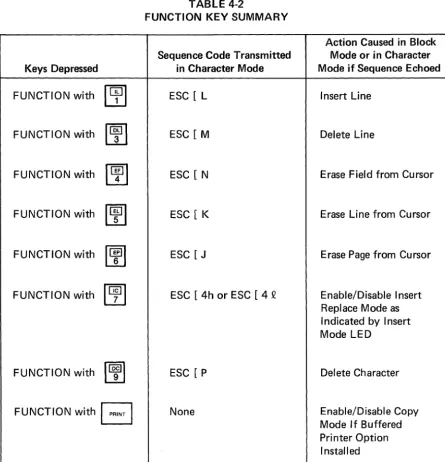
Depressing the FUNCTION key in conjunction with certain keys on the numeric keypad allows for editing functions to be performed from the key-board. In Character mode, the code sequence associated with each editing function will be transmitted and the editing function will be performed on the screen only if the transmitted code sequence is echoed.
In Block mode the editing function will be local only and no transmission will occur. Table 4-2 lists the codes transmitted and the editing functions per-formed for each depression of the FUNCTION key with keys on the numeric keypad.
Keys Depressed
FUNCTION with
~
FUNCTION with
~
FUNCTION with
~
FUNCTION with
~
FUNCTION with
~
FUNCTION with
~
FUNCTION with
~
FUNCTION with
B
TABLE 4-2
FUNCTION KEY SUMMARY
Sequence Code Transmitted in Character Mode
ESC [ L
ESC [M
ESC [N
ESC [ K
ESC [J
ESC [ 4h or ESC [ 4 Q
ESC [P
None
30
Action Caused in Block Mode or in Character Mode if Sequence Echoed
Insert Line
Delete Line
Erase Field from Cursor
Erase Line from Cursor
Erase Page from Cursor
Enable/Disable Insert Replace Mode as I ndicated by Insert Mode LED
Delete Character
8
GB
GB
GG
VISUAL TECHNOLOGY INCORPORATED, 540 MAIN STREET, TEWKSBURY, MA 01876
B
G
G
EJ
G
EJ
Causes the same action as the RETURN key.
This key is functional only if the Buffered Printer Option is installed and causes the contents of the screen to be sent out on the AUX PORT. If the XMITTER XON/XOFF feature is enabled, the XOFF code (DC3) will be sent to the host prior to the PR I NT function and the XON code (DC1) will be sent to the host upon completion of the PR I NT function.
If depressed with the FUNCTION key this key will alternately enable/disable Copy mode.
This key applies to Block mode only and causes a block trans-mission to begin when depressed. The portion of the screen to be transmitted depends upon the various transmission modes then enabled.
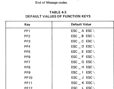
The twelve function keys, labeled PF1-PF12, are user program-mable as described in Section 5.3.6. If not programmed other-wise, each function key will transmit its default message as
indicated in Table 4-3. Please note that each function key trans-mission will be "framed" by the Start of Message code and Turn Around Control code when in Character mode. When in Block mode, each function key transmission will be framed by the Start of Message code and First and Second End of Message codes.
TABLE 4-3
DEFAULT VALUES OF FUNCTION KEYS
Key Default Value
PF1 ESC
-
A ESC\PF2 ESC
-
B ESC\PF3 ESC - C ESC \
PF4 ESC - D ESC \
PF5 ESC - E ESC \
PF6 ESC
-
F ESC \PF7 ESC
-
G ESC \PF8 ESC
-
H ESC\PF9 ESC
-
I ESC \PF10 ESC - J ESC\
PF11 ESC
-
K ESC\VISUAL TECHNOLOGY INCORPORATED, 540 MAIN STREET, TEWKSBURY, MA 01876
IKeys Special When SET-UP mode is entered, some keys on the main keyboard are used to to SET-UP change SET-UP features. Refer to Table 3-1 for a summary of each key and Mode: its function in SET-UP mode.
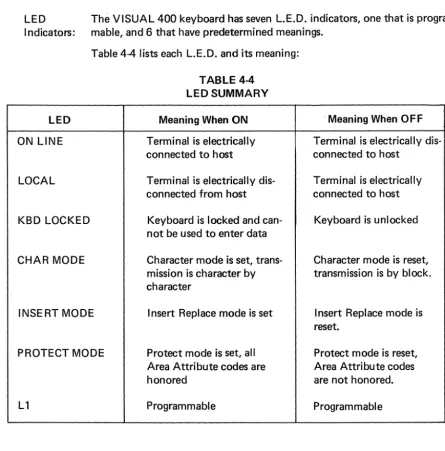
LED The VISUAL 400 keyboard has seven L.E.D. indicators, one that is program-I ndicators: mable, and 6 that have predetermined meanings.
Table 4-4 lists each L.E.D. and its meaning:
LED
ON LINE
LOCAL
KBD LOCKED
CHAR MODE
INSERT MODE
PROTECT MODE
L1
TABLE 4-4 LED SUMMARY
Meaning When ON
Terminal is electrically connected to host
Terminal is electrically dis-connected from host
Keyboard is locked and can-not be used to enter data
Character mode is set, trans-mission is character by character
Insert Replace mode is set
Protect mode is set, all Area Attribute codes are honored
Programmable
32
' Meaning When OFF
Terminal is electrically dis-connected to host
Terminal is electrically connected to host
Keyboard is unlocked
Character mode is reset, transmission is by block.
I nsert Replace mode is reset.
Protect mode is reset, Area Attribute codes are not honored.
VISUAL TECHNOLOGY INCORPORATED, 540 MAIN STREET, TEWKSBURY, MA 01876
5. TERMINAL PROGRAMMING
5.1 GENERAL
As previously noted, the VISUAL 400 operates according to the American National Stan-dard Institute (ANSI) X3.64 stanStan-dard for display terminals. This section details the control codes, modes, and control sequence functions used to control the VISUAL 400.
A reference card summarizing all remote commands is located near the rear of the manual, and Appendix I also summarizes remote commands.
5.2 CONTROL CODES
This section describes how the VISUAL 400 responds to received control codes. Control codes are defined as codes from columns one and two of the ASCII code chart and the DE L code (octal 177). Not