·c ..
-. /c
~._~
..
~
.. y.
~.~
_______________________
INTEIICOtIIIII,,"ICATIONTOI Commerc i al Branch Managers
CAR.OMS' Corrmercial Regional Managers
J. L~ Sturdevant
fROM (N"ME): H. L. Hughes
LOCATION & DATE: King of Prussia, Jan. 17,. 1965
OE~AItTIIDff: UDPD i vis ion EDUCAT ION
SuaJECT: ·UNI VPC 1005' EMPLOYEE TRAI NI NG
Product Marketing, Systems Programming, and the Curricula Development section of Education have cooperated in developing a UNIVAC 1005 Manual.
It is structured to aid in easy learning. We have made every effort to organize the material in a sound teaching format.
Final typing, illustrating, editing, printing, collating and distribution will require some additional time.
As an aid to you in providing your Sales Representatives and Systems Analysts training on the 1005, we have made copies of. the rough draft. THI SIS I NTENDED FOR I N-BRAI'CH USE ONLY AND .SHOULD BE DESTROYED WHEN THE FINISHED MANUAL IS RECEIVED BY YOU.
In order to insure complete accuracy of the finished manual, any errors should be reported by mail immediately to Mr. Art Levin, UNIVAC Product Marketing, P.O.Box 500, BlueBell, Pennsylvania. Questions concerning the Assembly System or the UNIVIC. 1005 should also be directed to Mr. Levin.
H. L. Hughes
hlh/len
·"
/ -
~.".'.'
"~.'."
\~/
..
OPERATH·TG PROCEDURE FOR 1005 ASSEMBLY
Machine Set up
Printer Punch
Processor
-Pass #1
Small Stock pape Blank 5081s.
1005 Control Panel
1. Alteration Switch #1 on
2. Place 1005 assembly Deck followed by Source Deck in
Processor.
3. Press start, Clear, Feed and Run (1005 wi1L.1oad assembly
Deck and Halt with Ind 1 on).
4. Turn off Alteration Switch #1 and Press Run
(1005 will now punch cards for Pass #2)
5. When Processor stops (Reader hopper Empty) Press Run
then StoE,.
6. Hold Source deck for Progra~ner.
*Pass #2
1. Remove cards from punch.
2. Place 1005 assembly Deck fo1101'led by cards (Pass 2, step 1)
in Processor.
3. Press Start clear feed and Run (1005 will punch out cards
for Pass #3 and print out listing of Pass #2)
4. When processor halts (Reader hopper empty)
press Run then Step.
5. Seperate Assembly deck from Pass #2 cards and discard
Pass #2 cards.
*Pass #3 Final Pass
1. Remove Cards from punch.
2. Place 1005 assembly deck, followed by cards removed
from punch, in Reader from Step 1 pass #3.
3. Press clear Start Feed and Run. (1005 will now punch
out Final object deck and print out of program).
•
..
-2-*Pass 1f3 Final Pass (Continued)
5. Scperate Assembly deck from Pass #3 dec~.
6. Discard cards used to punch out pass #3.
7 . Reinove cards from punch.
8. Put Run # on first card of assemb).ed program deck.
9. R.eturn source I Final object deck and listing to'
prograrmner.
*If machine jams, check light on punch stops processor or any other reason machine halt's during pass #2 or #3, that pass mUs-t be restarted with a RESTART CARD in Front of Assembly
deck. There is one Restart Pass 2 card and one Restart Pass 3
card. If Restart Pass 2 card is used Remove i t before starting
(
I
ROUGH DRAFT
COMPANY CONFIDENTIAL
UNIVAC 1005 ASSEMBLY SYSTEM
January 1%6
Data Processing Division Education
@
(
TABLE OF CONTENTS
SECTION PAGE
1.0 Introduction to the UNIVAC 1005 and Internally Stored
Prograrmling 1
1.1 Addressing Technique 1
1.2 Basic Logic and Format 4
1.3 Control Section Operation 5
1.4 Other Instruction Formats 7
1.5 Storage Allocation and Use 8
1.6 Ihdirect Addressing. 9
1.7 Other Special Registers 13
1.8 Special Register Locations 14
(
1.9 Addressing and Use of Column 32 152.0 Introduction to Assembly Systems 16
2.1 Purpose of Assembly Systems 16
2.2 Mnemonic Coding 17
2.3 .Symbo 1 i c Cod i ng 18
2.4 Relative Coding 19
/
2.5 Memory Mapping 20
2.6 Declarative Instructions 22
2.7 Assembler Processing 23
3.0 ' I ntroduction to the UNI VAC 1005 Assembly System 25
3.1 Terminology Definitions 25
3.3 3.4 3.5 3.2.1 3.2.2 3.2.3 3.2.4 3.2.5 3.2.6 label Operation
Operand 1
3.2.3.1
3.2.3.2 .
Operand 2
3.2.4.1
3.2.4.2
Remarks
Card Number IA
Field A·
+ Inc
lA,
Field B,±
IncField C,
::t
Inc.Operand 1 Address Specification
3.3.1
3.3.2
3.3.3
3.3.4
3.3.5
Symboiic Address (Label) Specification
Increments to Symbolic Addresses
Decimal Addressing
Rowand Column Addressing
Instruct i on Locat i on C'ouriter (I LC) Addressing
Operand 2 Address Specification
3.4.1
3.4.2 .
Operand 2, Field C, Blank Addressing
Operand 2 Indirect Addressing
Summary of Field A, Pie1d-B, and Field C Specifications
3.5.1
3.5.2
3.5.3
Field A
Field B
Field C
(~
(/
3.6 Standard Systems Labels
4.0 UNIVAC 1005 Assembly Instructions
4.1
4.2
4.3
4.4
Legend
Length of Operands
Transfer Instructions
4.3.1 4.3.2 4.3.3 .4.3.4 4.3.5 4.3.6 4.3.7
Transfer Descending
Transfer Ascending
Transfer Clear
Transfer Numeric
Transfer Constant
4.3.5.1
4.3.5.2
4.3.5.3
Symbolic Address Substitution
Row/Column and Decimal Addressing
Binary Coded Constants
Transfer to Register X
. Translate
Addition and Subtraction
4.4.1
4.4.2
4.4.3
4.4.4
4.4.5
Add Algebraic
Subtract Algebraic
Absolute Add
Absolute Subtract
Add Constant
4.6
4.7
4.8
4.9
4.10
Compar@ I ndr ions
4 .. 5.1
4.5.2
4.5.3
4.5.4
Compare Numeric
Compare Absolute
Compare Alphanumeric
Compare Constant
Condition Indicators
4.6.1
4.6.2
Set Condition
Stop
Sequence Control Instructions
4.7.1 4.7.2 4.7.3 4.7.4 4.7.5 4.7.6 4.7.7 Count
Jump Condition
Jump Test
Unconditional Jump
Jump Return
Jump Compare
Jump Loop
Jump I nd i reet
Edit Instructions
4.9.1
4.9.2
4.9.3
4.9.4
Edit Logical
Edit Erase
Edit Superimpose
Edit
Declarative Instructions
4.10.1
4 .. 10.2
Define Instruction Location Counter
Defi ne Area
4.10.2.1
4.10 .. 2.2
Define Sub-field
Redefine Standard Label
(
4.10.3 Define Constant 151
4.10.3.1 In-line Constant 154
4.10.3.2 In-line COlTment 155
,
4.10.4 Defi ne I ndi rect Address Constant '1574.10.5 Define End 161
r
4.11 MUltiplication Instructions 1624.11.1 Multiply 164
4.11.2 Multiply (Long) 167
I
4.12 Divide Instruction 1694.12.1 Divide 171
4.13 Input au~put Instructions 174
4°.13.1 Shortened General Commands 175
(
...
4.13.2 General Commands 176
4.13.3 Read Magnetic Tape 182
4.13.4 Wrtte Magnetic Tape 184
4.13.5 Receive Data Line 186
4.13.6 Send Data U ne 187
4.13.7 Receive Interface 189
4.13.8 Send Interface 191
o
1
f
Ij
I
INTRODUCTION TO THE UNIVAC 1005
AND I NTERNALLY SHRED FROffiArvM I NG
1.0 The UNIVAC 1005 is classified as a general purpose, stored program,
digital computer. The main store consists of either two or four banks
of core memory with 1024 locations per bank. In addition to providing
storage for instructions and data, two types of Special Registers are
provided in core memory to control the operation of the UNIVAC 1005.
The special registers are addressable and in some cases can be used
as additional data storage.
1.1 ADDRESSING TECHNIQUE
Each bank of core memory consists of a 32 row by 32 column
matrix of 6-bit memory locations. Each location is addressed by
specifying its Rowand Column coordinates. For example; the
first memory location has an address of Row 1, Column 1; the
last memory location has an address of Row 32, Column 32. These
address designations are abbreviated to R1/C1 and R32/c32.
In order to store the address of a single location in
memory, the six bits of two adjacent memory locations are required.
Five of the six bits of the left-hand location are used to specify
the Row coordinate, and five of the six bits of the right-hand
location are used to specify the Column coordinate. A combination
of the sixth bits of both locations is used to specify which of
the four possible banks of memory is involved.
The UNIVAC 1005 utilizes a special 5-bit concept which operates on
a logical rather than a binary arithmetic basis. Special combinations
of these fiVe bits are employed for the values 1 to 31 used as row
or column coordinates. These 5-bit combinations, plus the sixth
bit required for bank designation, correspond to the 64 characters of
the UNIVAC 1005. Thus, the address of any location in any bank of
core memory can be specified by the proper selection of two of these
6-bit characters.
The foregoing description indicates the similarity and compatibility
of the memory of the UNIVAC 1005 and the UNIVAC 1004.
For the purpose of stored-programming, the main store of the UNIVAC
1005 should be considered as 1922 (or 3844) consecutively numbered,
decimally addressed memory locations enclusive of the Special Registers
and Column 32 of card row. The physical arrangement of main store
is then no longer a concern of the programmer. Using this method,
the main store of the UNIVAC 1005 takes on the following appearance:
Banks 1 and 2
1 100
101 200
201 300
BANKS 1 and 2
.-
~'\ ;
:>
H·
--~.-(
r-
J---)
1701 1800
1801 1900
1901 -1.m.]
o
o
(~
c
--11923 -- 2000 1
i . .2~ ____ . 2100
2100 .--- 2200
BANKS 3 and 4 ~
<;
S
~
) .. J
~
---
---3601
-3701 _______ 3700 3800 3801 3844
I
Decimal addressing would then produce the following facility
for programming:
First location of Read Input Storage (Card Col. 1)
Last location of Read Input Storage (Card Col. 80)
First location of Print Storage (Print POSe 1)
Last locafion of Print Storage (Print POSe 132)
First location of Punch Storage (Card Col. 1)
Last location of Punch Storage (Card Col. 80)
Decimal Adr. 1
80
161
292
293
372
Since Print Position 1 is located at address 161, Print Position
23, for example, is located 22 positions away at address 183.
This same convenience IS extened to the addressing of the programmer's
data areas as well as to the other reserved areas of Input Output
storage. A complete description of decimal addressing as provided
by the UNIVAC 1005 Assembly System appears in Section of
this manual.
1.2 BASIC LOGIC AND FORMAT
The UNIVAC 1005 operates on a basic two address instruction logic.
A UNIVAC 1005 instruction contains the a'ddress of two pieces of
information called Operands, and an operation code for the process
to be performed with these Operands. The Operands are defined by
specifying the address of the most significant location
(abbreviated MSL), or the address of the least significant
location (abbreviated LSL), or both, depending on the operation
to be performed. Operations are specified by a one character code.
The majority of the UNIVAC 1005 instructions reqUIre Seven character
locations in the following format:
OP
I
AI
BI
C1.
OP is
a single character which specifies the operation to be performed.
A is the two character address of the location of either the MSL or
the LSL of Operand 1. B is the two character address of the
location of the MSL of Operand 2. C is the two character address
of the location of the LSL of Operand 2.
o
(
Instructions are executed in ascending (LSL to MSL) or descending
(MSL to LSL) mode. If the operation is performed in ascending
mode, the A portion specifies the LSL of Operand 1. If the
operation is performed in descending mode, the A portion specifies
the MSL of Operand 1. The use of UNIVAC 1005 character codes to
specify operation codes and addresses is called absolute coding
or machine coding. A table of these codes and their equivalents IS
shown in Appendix _ _ • As will be explained in succeeding sections
of this manual, the UNIVAC 1005 Assembly System provides a
convenient method of specifying these codes. The output of the
Assembler processing IS a deck of punched cards containing
instructions in machine code. These cards are read by the UNIVAC
1005 and the instructions stored in core memory under the control
of a Load program which is provided for the UNIVAC 1005. The Load
program is initiated by a special header card which is placed in
the front of the instruction cards.
1.3 CONTROL SECTION OPERATION
After the program has been loaded, operation of the UNIVAC 1005
proceeds under the control of the Instruction Control Counter(ICC).
The ICC is one of the Special Registers located in core memory.
The ICC IS a two character register which contains the address
of the MSL of the instruction to be performed next by the UNIVAC
1005. As each instruction IS accessed for execution, the contents
of the ICC are incremented by the number of characters in the
instruction--usually seven. This increment is first added to
When the Column count passes 31, an increment of one is added
to the Row address portion of the ICC, and the Column portion
is returned to 1. Memory Bank specification is also advanced as
the Column count passes 31. Thus the access and execution of
instructions proceeds in a sequential manner. Instructions are Row 32 provided to vary this sequential operation when required.
0
1and Column 32 addresses are not included in the sequential advance of the ICC.
As each instruction. is accessed, according to the address in
the ICC, it is transferred to the Instruction Register (IR).
The IR is a seven character Special Register which is used to
examine the instruction. The bit configuration of the one character
Operation code is analyzed by the circuitry which establishes and
controls the functions necessary to perform the required operation.
The address portions of the IR are transferred to the internal
storage address controls for
OP
1 andOP
2. The norma~ operationof the UNIVAC 1005 when executing instructions is to access the
first character from either the LSL or the MSL of
OP
1, and thecorresponding character from
OP
2 (LSL or MSL) and perform theprocess. The determination of whether the LSL or the MSL is used
is based on the mode--ascending or descending--of the instruction.
After operating on the first characters from
OP
1 andOP
2, theoperation proceeds with successive corresponding characters of
OP
1and
OP
2 until the processing of the last character location ofOP
2 has been completed. This signals the end of the instruction.During the execution of each instruction, the contents of the ICC
~re incremented according to the number of characters in the
instruction itself. When the end operation signal is generated,
the new address in the ICC is used to control the access of the
(~ ..
"
next instruction eNI). The execution of the program proceeds in
this manner to direct the UNIVAC 1005 to accomplish the desired
results.
1.4 OTHER INS1RUCTION FORMATS
The instruction repertoire of the UNIVAC 1005 includes a complete
set of commands for control of the operation of the system. In
addition to the type of commands previously mentioned--seven
characters, with an OP 1 and an OP 2 address--there is a second type of co~mand which provides for flexibility and ease
of control of the programming requirements necessary to internally
stored program operation.
The second type of instruction 1S five characters 1n length and
has the following format:
OP A B
Where:
OP
=
a one character operation codeA
=
a two character constant whose value is used or whosebit configuration is used to perform special functions
B
=
a two character address of the location in memory wherethese operations and functions are performed.
As is the case with ~ost stored program computers, there are
special commands in the UNIVAC 1005 with a format that does not
precisely conform to these two basic formats. These special
commands will be either five or seven characters in length, and
the format variation will be indicated along with a complete
description of the operation~
1.5 STORAGE ALLOCATION AND USE
The main st.ore of t.he UNIVAC 1005 is separat.ed ~ ~ hardware int.o
t.wo major'areas--input. out.put. st.ore, and working store. Input output
st.ore consist.s of selected port.ions of memory reserved f6r the
informat.ion received from and t.ransferred t.o t.he inpu\l6ut.put.
devices. When a reserved area is not. required for a device
as input/output. st.ore due t.o t.he operat.ions being performed, t.he
area can be used by t.he programmer for st.orage of inst.ruct.ions
Qr dat.a. The working st.ore consist.s of ·t.hose portions of memory
not. reserved for input.;6ut.put. informat.ion--t.he remainder of
core memory.
The working store is separat.ed ~ ~ proerammer into t.wo t.ypes
of areas according t.o his programming requirement.s. A portion of
working st.ore is est.ablished by t.he programmer t.o store t.he
informat.ion (other than
inpu~ut.put.)
t.o be processed. There-mainder of working st.ore is used t.o st.ore the program inst.ruct.ions.
A not.e should be made at. this point. that t.he addressing capability
of the instruction address ext.ends to all of main store. This
means t.hat the content.s of any memory locat.ion or locat.ions can be
accessed as dat.a t.o be processed. This includes t.hose locat.ions
used by t.he programmer to store inst.ruct.ions. The use of this
capability t.o operat.e on inst.ruct.ions as if t.hey were dat.a IS
an import.ant. technique of internally st.ored programming.
0 ,
.
'c
1.6
(--INDIRECT ADU~ESSING
Another facility provided by the UNIVAC 1005 is the ability to
perform Indirect Addressing. In the UNIVAC 1005, Indirect
Addressing is the ability to specify in the address portion of
an instruction the address of the memory location which contains
not the data to be processed, but a secondary address which
specifies the location of the data to be processed. From a
hard-ware standpoint, this is accomplished by using the primary
address--the address in address--the instruction--to control address--the transfer of address--the
secondary address to the IR where it is then used as the
address of the data to be processed.
From a programming standpoint, Indirect Addressing allows
the programmer to establish one series of instructions which
perform
a
programming operation on separately stored but related items of information. This is accomplished by programming theinstructions once using primary addresses, and changing the
secondary address to refer to the proper item for each uSe of
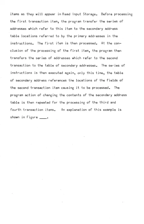
the series of instructions. For example: a detail card contains
four twenty-column transaction items. Each item contains four
five-column fields. The program IS written using primary
addresses which refer to a table of secondary addresses. The
table is set up to refer to the address of the fields within
an item. A series of addresses in the form of constants is
created by the programmer and stored in a portion of working
store. There is a series of addresses for each of the transaction
items as they will appear in Read Input Storage. Before processing
o
the first transaction item, the program transfer the series ,of
addresses which refer to this item to the secondary address
table locations referred to by the primary addresses in the
instructions. The first item is then processed. At the
con-elusion of the processing of the first item, the program then
transfers the series of addresses which refer to the second
transaction to the table of secondary addresses. The series of
instructions is then executed again, only this time, the table
of secondary address references the locations of the fields of
the second transaction item causing it to be processed. The
program action of changing the contents of the secondary address
table is then repeated for the processing of the third and
fourth transaction items. An explanation of this example is
shown in Figure ____ •
o
(-READ INPUT STORAGE TRANSACTION ONE
: FIELD 2: FIELD 3 : FIELD 4
TRANSACT ION TWO
i FIELD 2 ;
~ _ _ -4-~ _ _ ..!...!1 O.-:..J...:..1 _ _ ---"~~:-:-:-~~~=~..p...:..~::...--~3Q 31 __
3:
FIELD 4I
___
~~~
_ _~~~~~~_~5Q~j
__~~5~~~5~6
_ _~6~d~6~1
_ _ _ _-
-
--
-
---
-
- - - --
--
- - - -- -
---
--
-
...SECONDARY ADDRESS TABLE ENTRY 2 ENTRY 3 ENTRY 4 Am. OF ADR. OF ADR. OF
FIELD 2 FIELD 3 FIELD 4
MSL LSL MSL LSL 1234 1 2 3 4
-
-
-
- -
-
-
-
-
--
--
-
-
-
;."
-
-
- - -
---
-
-
-- -
- --
-
---"... "",.----
---"
I '\,
\ \,
I JI • ______________________________________________ _
''''''; CONST ANT STrn AGE '
EN~Y 1 { I
ENTRY 2
ENTRY 3
ENTRY 4
\
,
ADR. OF
FD. 1. ITEM 1
Am:
-o"F- ---
-FD 1. ITEM 2 ADR. OF
FD. 1. ITEM 3 Am. OF
FD 1 ITEM 4
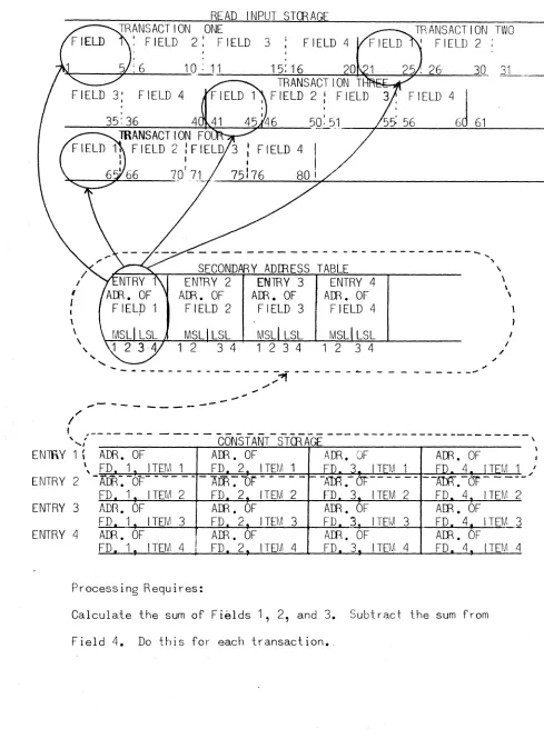
Process i ng Requ ires:
Am. OF
FD 2. ITEM 1
Am7"DF --
-
-FD 2. ITEM 2 Am. OF
FD 2. ITEM 3 Am. OF
FD 2 ITEM 4
Am. OF Am. OF
£D 3~ ITEM 1 i l l 4 iTEM 1 -A"Ili.-or--
-
- - ~. OFFD 3" ITEM 2 FD 4 ITEM 2 Am. OF Am. OF
FD. 3. ITEM 3 FD. 4, ITEM 3 Am. OF Am. OF
FD 3 ITEM 4 FD 4 ITEM 4
Calculate the sum of Fields 1, 2, and 3. Subtract the sum from
Field 4. Do this for each transaction •.
Instr. 1 2 3 4 5 6 ",
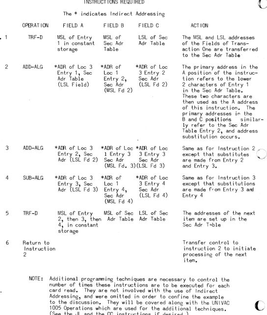
INSTRUCTIONS REQUIRED
Oi
The * indicates Indirect Addressing
o
PER AT ION FIELD A FIELD B FIELD CTRF-D MSL of Entry MSL of LSL of Sec 1 in constant Sec Adr Adr Table storage Table
ADD-ALG *ADR of Loc 3 *ADR of *ADR of Loc Entry 1, Sec Loc 1 3 Entry 2
Adr Table Entry 2, SecAdr (LSL Field) Sec Adr (LSL Fd 2)
(MSL Fd 2)
ADD-ALG *Affi of Loc 3 *ADR of Loc *Affi of Loc Entry 2, Sec 1 Entry 3 3 Entry 3 Adr (LSL Fd 2) Sec Adr Sec Adr
(MSL Fd. 3)(LSL Fd 3)
SUB-ALG *ADR of Loc 3 *Am of *ADR of Loc Entry 3, Sec Loc 1 3 Entry 4 Adr (LSL F d 3) Entry 4, Sec Adr
Sec Adr (LSL Fd 4) (MSL Fd 4)
TRF-D MSL of Entry MSL of Sec LSL of Sec 2, then 3, then Adr Table Adr Table 4, in constant
storage
Return to Instruction 2
ACTION
The MSL and LSL addresses of the Fields of Trans-action One are transferred to the Sec Adr Table
The primary address in the A position of the instruc-tion refers to the lower 2 characters of Entry 1
in the Sec Adr Table. These two characters are then used as the A address of this instruction. The primary addresses i~ the Band C positi6ris
similar-ly refer to the Sec Adr Table Entry 2, and address substitution occurs.
Same as for Instruction except that substitutes are made from Entry 2 and Entry 3.
Same as for Instruction 3 except that substitutions are made from Entry 3 am Entry 4
The addresses of the next item are set up in the Sec Adr T",ble
Transfer control to
instruction 2 to initiate processing of the next
item.
NOTE: Additional programming techniques are necessary to control the number of times these instructions are to be executed for each card read. They are not involved with the USe of Indirect Addressing, and were omitted in order to confine the example to the discussion. They will be covered along with the UNIVAC 1005 Operations which are used for the additional techniques.
(See the JL and the CC instructions if desired.)
c
ldo
- - - -
(
' . ,The normal use of Indirect addressing is with data which
contains a multiple item format similar to the punched card
format in the preceding example. The multiple item concept IS
generally used for magnetic tape master and detail files. The
use of the Indirect addressing capability of the UNIVAC 1005 is
not restricted to the multiple item concept.
Other UNIVAC 1005 Operations and capabilities designed to implement
stored programming techniques are described in this manual along
with an example of the application of the technique.
:;. .
1.7 OTHER SltC I AL REG I STrnS
There are two Special Registers In addition to the Instruction
Control Counter and the Instruction Register. These are the
Multiply/Divide Register (MDR), and a multi-purpose register
called Register X (rX).
The MDR is 31 locations in length, and is used by the Multiply
and Divide instructions. i~hen not required for this purpose, the least
significant 22 locations ~ay be used for intermediate programming results.
Register X is 31 locations in length and is used primarily when
Add or Subtract operations involve Operands of unequal length.
When not required for this purpose, rX can be used for intermediate
results of programming operations.
-- ---~---~~
A thorough explanation of the use of rX and the MDR is given in
this manual where the Operations which reference them are discussed.
It should be remembered that all Special Registers are located in
core memory, are explicitly addressable, and are in addition to
the basic two or four banks of main store.
1.8 SPECIAL REGISTER LOCATIONS
The Instruction Register (IR), the Instruction Control Counter
(ICC), and the Multiply/Divide Register (MDR) constitute 'an
extra row of core memory--ROW 32. This set of special registers
is in ROW 32 of BANK 1.
1 ROW
1 COLUMN 31
IR IICCI MOO
32~~~~1~~~
1 7 8 9 10 31
BANK 1
Register X constitutes an extra row of core memory-~OW 32 of BANK 2.
1
ROW
1 COLUMN 31
rX
32 ~ _ _ _ _ _ ---"
1 31
BANK 2
When the ICC is incremented for sequential access of instructions,
it advances from R31/C31 of Bank 1 and Bank 2, to R1/C1 of Bank 2
and Bank 3 respectively, thus bypassing the special registers. The
use of decimal addressing does not include the specification of the
addresses of the Special Registers. They can be addressed using the
Row/Column addressing provision of the UNIVAC 1005 Assembly System.
-o
o
1.9
r
ADffiESSING AND USE OF COLU:~N 32
Each of the 32 Rows of memory contains 32 columnar positions.
The allocation of memory by the Assembler program is made on
the basis of 31 Rows and 31 Columns per Bank. As described
in Section 1.8, Row 32 of Bank 1 and Bank 2 are excluded from
Assembler allocation and are used for the Special Registers.
The explanation of the advance of the Rowand Column portions
of the Instruction Control Counter indicates that not only is
ROW 32 of memory bypassed, but also COLUMN 32 of each Row of
memory IS also excluded f~ Assembler allocation.
Column 32 of each Row in Bank 2, 3, and 4 become a series of
one characler locations whkh can be used by the programmer for
such things as single character constants, control settings,
program switches, etc. Decimal addressing does not include the
addressing of any Column 32. The Row/Column addressing provision
of the UNIVAC 1005 Assembly System provides the means of addressing
each of these single character locations.
NOTE: Column 32 of each of the Rows in Bank 1 are reserved for hardware/software control purposes and must not be used by the programmer.
Row 32 of Bank 3 and Bank 4 are also not included in the allocation
processing of the Assembler program. Row 32 of Bank 3 and Bank
4 can be used by the programmer for the storage of data and
intermediate results of processing.
INTRODUCTION TO ASSEMBLY SYSTEMS
c
2.0
NEED FOR ASSEMBLY SYSTEMS
Control of an internally stored program computer is accomplished by
providing the computer wrth a set of instructions which have
been designed to produce the desired results. These instructions
,
i
are created by the programmer according to the specific requirements
and capabilities of the computer. The 'instructions must be entered
,
in the computer memory in a specific sequence using a precise
set of characters. This set of characters constitutes the
vocabulary or language of the machine. Machine languages are
dictated by the design characteristics of the computer and seldom
bear any relationship to human language. Furthermore, machine
languages seldom follow any logical pattern that a person could
use when writing a program. In addition to the language barrier,
there are many clerical-type functions which a programmer must
perform when writing a program.
2. 1
PLR POSE OF ASSEMBLY SYSTEMS
In order to overcome the language barrier, and to provide the
programmer with clerical-type assistance, an assembly system
is usually provided as part of the software of an internally stored
program computer.
The assembly system allows the programmer to use a
machine-oriented language which is also human machine-oriented. The programmer
o
Ii:>
[c
!
t
c-writes the instructions in assembly language according to the
rules of the assembly system. These instructions are punched
into cards and are read into the computer under the control of
a program called the assembler program. The assembler program
analyzes the assembly language instructions and translates or
converts this language into the precise machine language of the
computer. An output deck of punched cards is produced by the
assembler processing which contains the machine language
instructions. This deck of cards is then read into the computer
under 'the control of a load program which stores the instructions
in the required sequence. The computer is then instructed to
execute the program.
The deck of cards which contains the instructions written in
assembly language is called the source deck. The output deck of
cards which contains the instructions in machine language is
called the object deck. In some cases, the assembly language is
referred to as the source language or source code, and the
machine language is referred to as the object language or object
code.
2.2 MNEMONIC CODING
The terms mnemonic, symbolic, and relative coding are sometimes
erroneously used as synonyms. Each term has a specific meaning,
and each one constitutes an important characteristic of an
assembler.
An assembly language usually contains a set of mnemonic codes
which represent the Operation codes of the computer. These
mnemonic codes are established to help the programmer remember
the code to be used for the Operation needed.
In addition to the mnemonic codes which correspond to the specific
commands of the computer, an assembler usually provides a set of
mnemonic codes for pseudo-operations. The pseudo-operations are
established for the stored-programming functions which t~e
programmer normally needs to implement his problem solution.
These pseUdo-operations usually represent options of computer
Operation codes and are glven mnemonics which make it easier
for the programmer to specify his needs. In some cases the
pseUdo-operation represents a combination of two or more computer
instructions which are needed to implement a stored programming
technique.
2.3 SYMBOLIC CODING
Symbolic codes are a usual provision of' an assembly language to
allow the programmer to assign meaningful names to important
information within his program. For example, the fields of data
in a payroll card are known to the programmer by the type of
information they contain, such as Employee Number, Department,
Gross Pay, etc. There is normally a limitation on the length of
a symbolic name. However, this length is usually enough to permit
meaningful abbreviations or contractions. In the example above,
the Employee Number field could be named EMPNO; the Department
o
o
o
I
lc
field could be named DEPT.; the Gross Pay field could be namedGAPAY. As will be discussed in the section on memory mapping, the
actual addresses of these fields in memory are assigned· by the
assembler program. When the name or label appears anywhere in
the source language instructions, the assembler program will use
the assigned actual address in the object language instruction.
Symbolic labels are also assigned to instructions In the program
which are referenced by'other instructions in the.program. When
a non-sequential transfer of control is required from one series
of instructions to another, the programmer must specify the point
to which control is to be transferred. Since actual addresses are
assigned by the assembly program, the programmer cannot provide
the actual address. By labelling the instruction to which control
is to be transferred, he.can use the symbolic address for the
same purpose.
2.4 RELATIVE CODING
Relative coding is another assembly system technique which
allows the programmer to specify the location of instructions and
data, even though the actual addresses are assigned by the
assembly program. To use the relative coding technique, the
programmer must have a thorough understanding of the memory
mapping operation of the assembler program. Once this is
understood, relative coding is a simple yet powerful stored
programming technique. In the preceding section on symbolic
coding is an explanation of the assembler program assignment of
2.5
V
addressAto symbolic labels. This creates a common fixed point
of reference between the programmer and the assembler program.
By using this common fixed point of reference (the label) as a
base, the programmer can specify other locations by their position
relative to the base. For example, if the memory location
which is to contain the information from card column 1 has been
given a label of DETCD, then the memory location which is to
con-tain the information from card column 5 would be 4 locations away.
By specifying an Operand label of DETCD + 4, the programmer causes
the assembler program to assign the actual address of the operand
by mathematically adding the increment of 4 to the actual address
of DETCD. The assembly system usually provides for decrements to
symbolic labels as well as increments.
MEMORY MAPPING
In order to assign the location of instructions and data, the
assembler program must keep track of the locations that are used
as the assembler processing is performed. To do this, the
assembler program contains an Instruction Location Counter (ILC).
This is a program created device, not a piece of hardware. The
loading of the assembler program itself usually sets the ILC to
the actual address of the first memory location. The assembler
program then causes the reading of the first source language in~
struction. This instruction is assigned to an actual address
according to the present value of the ILC (in this case, the
first memory location). After the machine language for the
1
oj
~ I
o
(-c
instruction has been created by the assembler processing, a card
is punched containing the machine language instruction. The
number of locations that will be required to store the instruction
is added by the assembler program to the ~alue of the ILC creating
a new value in the ILC. The assembler program then causes the
next source language instruction card to be read. This instruction
is assigned to an actual address according to the present value
of the ILC. Assume that the actual address assigned to the
preceding instruction had been R25/C1 and that the instruction
was seven characters in length. (R25/C1 becomes the address of
the MSL of the instruction.) The assembler program would then
add seven (the number of locations for the fi rst instruction)
to the machine code equivalent stored in the ILC, and arrive at
the machine code equivalent of R25/C8. This IS the actual address
assigned to the second instruction assembled.
The use of this procedure by the assembler program insures that
the assignment of addresses to instructions follows the sequential
access of the instructions by the computer w~en the object program
is executed.
In addition to an ILC, an assembler program may contain a Data
Location Counter (DLC). The DLC provides the programmer with the
ability to assign locations to his data in an area of memory other
than the area to be used for instructions. Instructions are
usually assigned to locations starting with the first memory address
Clow-numbered locations) and proceeding in ascending sequence.
Data is usually assigned to locations starting with the last memory
2.6 DECLARATIVE INSTRUCTIONS
An assembly system with an ILC and a DLC usually provides a set
of pseudo-operations which allow the programmer to establish and
modify the value in the location counters. In addition to the
pseudo-operations which manipulate the ILC and the DLC, there
are usually other pseudo-operations which are required to instruct
the assembler program as to the manner in which the assembly
processing is to take place. These pseudo-operations are called
declarative instructions. Unlike the previously mentioned
pseudo-operations, declarative instructions, which are included
in the source language deck, do not produce instructions in
the object language deck. The declarative instructions are for
the use of the assembler program during the assembly processing,
and not for the computer as part of the object program.
An example of a declarative instruction would be one that updates
the DLC. Assume the problem called for storing the contents
of a header card to print headings on each new page. The
programmer would label the source language instruction line, write
the mnemonic pseudo-operation code that decrements the DLC, and
indicate the value of the decrement (the number of locations to
be reserved for the data). Such a line of source code might
appear as
Label HDRCD
OP Code DA
#
of Locations 80(stands for Define Area)
F-'.
I
I','
."L/.
1
I
~
1
,
(
When this line of source coding is encountered, the DA tells the
assembler progra~ to refer to the DLC. The contents of the
DLC are decremented by the number of locations to be reserved.
The new value of the DLC is assigned as the address of HDRCD. In
order to reference the information .in the HORCD area, the programmer
can use relative coding.
2~7 ASSEMBLER FROCESSING
An assembler program consists of a set of machine code instructions
designed to produce specific results. As is the case with any
computer program, the assembler program is designed to receive
specific information prepared in a precise format. It is the
responsibility of the programmer to prepare the source language
program deck according to the rules of the assembly system. Any
errors in the source language will produce incorrect results from
the assembler processing.
In order to produce a complete object program, the assembler program
must read-the entire source program before producing any object
instruction cards. During the reading of the source cards, the
assembler program performs a preliminary· analysis and converts
or translates from source language to object language wherever
possible, eg: the mnemonic operation codes. As each source card
is read and the mnemonic operation code IS translated, the
assembler program determines the length of the instruction. The
instruction is assigned to an actual address, and the ILC is
symbolic address by the programmer, the label and the 3.ctu3.1
address are stored in a table. When these labels appear in
the source language instructions as Operand addresses, the
assembler program searches the label table using the symbolic
address as the key, and secures the actual address assigned to
the label. The actual address is substituted for the programme?s
symbolic operand address.
The assembler program contains many other tables which it
references for conversion of the source language to object
language. After complete analysis and conversion of the source
language, the assembler program causes the object program to be
listed and punched.
1(,
c
3.0
INTRODUCTION TO THE UNIVAC 1005 ASSEMBLY SYSTEM
Most of the programs for the UNIVAC 1005 will be written in
the language of the UNIVAC 1005 Assembly ~ystem. The UNIVAC 1005
Assembly System provides the programmer with the necessary
functions and convenience described in the preceding section.
The use of instruction forms not described in this manual deviates
fro~ UNIVAC recommendations and must be the user's responsibility.
3.1 TERMINOLOGY DEFINITIONS
3.2
3.2.1
Alphabetic means a letter from the English alphabet (A through Z)
Numeric means an Arabic numeral (0 through 9)
Alphanumeric means the entire 64 character set of the UNIVAC 1003 which includes letters, numbers, and spe~ial characters.
COD I NG FffiM
A coding form to be used to record the programmers instruction
for subsequent key punching and processing by the UNIVAC 1005
Assembler program is shown in Figure ____ • The coding form IS
set up in the same format as the punched card, and contains an
indication of the card columns to be used for each field.
LABEL
LABEL Columns 1 through 5
5
_.~._ .. ! .. L.
This field is provided for the symbolic Labels which are assigned
to those lines of coding which are referenced by the object
program instrudio'ns. A label may consist of from one to
five...--characters (inclusive) and must begin in column 1 of the field.
The first (left-most) character of a Label must be an alphabetic
alphabetic or numeric. There is no limit to the number of Labels
in a source program. However, if more than 40 Labels are used,
extra processing is required by the Assembler program. This is
fully explained in the section on Operating the Assembler System.
Five positions are provided in the Label field to allow meaningful
assignment of programll'3r names. However, only the left-most three
positions of a Label are significant to Assembler processing. The
first three positions of each Label must be unique within a
program. Extreme care should be taken when creating Labels.
Labels used in a single program must be unique and may appear
only once in the Label field. Labels will be used in the
Operand address portion of instruction lines and may appear there
as often as necessary. The explanations in this manual of the
use of the relative coding technique of increments and decrements
to Labels should enable the programmer to address the data in his
program without an excess of Labels.
The Label of a line of coding becomes the symbolic' address for
the left-most (MSL) position of the instruction, and is used
whenever the instruction is referenced. Labels are also used for
the lines of coding which define data areas, and become
the symbolic address for the left-most (MSL) position of the
area set aside for data.
~
(
r
(
Since not all lines of coding require a label, the field may be left
blank. Some examples of labels are: LABEL
3.2.2 OFtRAT ION Columns 6 through 10
~PERATION
6 1D
--L--L-L.-.L
This field IS for the mnemonIC operation codes provided by the
Assembler. Operation codes are usually alphabetic. The majority
of Assembler Operation codes are two characters in length, and
must begin in column 6.
Some examples of Operation codes are:
PERAT I or~
:·6 10
: f\:».
I !;5
Iv..
I I!
~
OPERAND 1
~ FIELD A + INC :* .12 '16 18 ?C
3.2.3
OPERAND 1
~l
This is a heading for those columns which are normally used to
specify the address of the MSL or LSL of OP 1 depending on the
ascending or descending mode of the instruction. This portion of
the coding form is also used for other purposes, since not all
Operations involve an Operand 1. The following description of
the OPERAND 1 fields is based on the normal use to specify OP 1
addresses. A complete explanation of Operand 1 addressing begins In Section ~.
3.2.3.1 IA Column II
This column is used to indicate Indirect Addressing. When the
OP 1 of an instruction is a primary address, an asterisk
(*)
isplaced in this column. It must be' left blank at all other times. \
3.2.3.2 FIELD A Columns 12 through 16
This field of the form will normally contain a programmer's symbolic
address for the location of instructions and data within his
program. Any Labels which appear here must also appear in the
LABEL field of some line of coding. Field A is a five position
field for OP 1 Labels which normally begin in column 12. +
3.2.3.3 - INC Columns 17 through 20
These columns are normally used to indicate an increment to the
address assigned to a Label. Increments are shown in decimal
numbers. If column 17 contains a plus sign (+) the increment is added. If column 17 contains a minus sign (-) the increment becomes
o
as
I
•
l
,
I•
a decrement and is subtracted from the Label address. Increments
must be left-justified (begin in column 18). OPERAND
1
Some examples of OPERAND 1 addresses are:
*
FIELD A2 16
I J i
--_ ... - - - _ ..
OPERA In 2
3.2.4. OPERAND 2 I~ FIELD B
+
INC FIELD C...
INC*
22 26 -- 28 30 32 36 -be /10.
I J _I ~ ....L JThis is a heading for those columns which are normally used
to specify the MSL and LSL addresses of Operand 2 in the instruction.
This portion of the form is also used for other purposes. The
following description of the OPERAND 2 fields is based on the
normal use to specify OP 2 addresses. A complete description of
OPERAND 2 addressing IS found in Section 3.3.
3.2.4.1 lA, FIELD B;tINC Columns 21 through 30
These fields are normally used to specify the most significant
location (MSL) of OP 2. The description of the contents of
these fields is the same as the description of the contents of
OPERAND 1.
3.2.4.2 FIELD C,
±
INC Columns 32 - 40These fields are normally used to specify the least significant
location (LSL) of OP 2.
The description of FIELD C and! INC is the same as the
3.2.5
COMMENTS Columns 41 through 56C.·~~M't~
1141 ~, ~'
correspondinQ fields of OPERAND 1.
t l _ J--..l._L .J ..
L-J._L ....
.L. I I I I I I 11This PQ~tion of the form is provided to allow the programmer
to include pertinent remarks as to the purpose of the line or
lines of coding. The remarks are not considered by the Assembler
processing and merely pass through to the printed and punched
output. These columns are also used to indicate constant values
which are to be included in the object program. This use is
described In the section which covers Constants. If the RDMfl;I(S (j\)M~f.M'S
.e.
exceed )( positions, a COMMENT line of coding may be used.
(See Sect ion ___ .)
3.2.6. CM D NUMBER Columns 62 throuah 66 ::>
This portion of the form is subdivided into three
fields--PAGE NUMBER, LINE NUMBER, and INSERT NUMBER. These colu~ns are
used to indicate the number of the page of coding, and the number
of the line from which the key punched card was produced.
The Card Number field will assist the key punching effort as well
as provide for the re-sequencing of the cards in the event the
original sequence is disturbed. For proper assembly proceSSIng,
. it is necessary that the cards be read by the Assembler program in the
sequence in which they appear in the source program. The Card Number
field is used for external control purposes only. The Assembler program
does not check the sequence as it reads the card.
- - - -
-30
i
,£',
!
L,,'
f:
o
,
~
,
,
(~
3.2.7
The INSERT NUMBER colu~n is provided as a facility to insert
additional lines of coding in a source program, after the
initial effort, without disturbing the sequence established by
Page and Line Number.
During the assembly processing, the Assembler program assigns
a consecutive number to the output cards in the object program
deck. The Assembler assigned card number is punched into
colu~ns 62 though 65. Column 66 is blank In the o~tput card.
The remainder of the card columns are not examined by the
Assembler program, and are available for whatever use the
programmer may determine. Such things as Job Number, Programmer's
Initials, and Date may be included on a repetitive punching basis.
These items will not appear in the object deck. Card Columns 67
through 73 are used for the object language instructions, and
columns 74 through 80 are used for instructions to the Load
program •
.
3.3 OPERAND 1 ADDRESS SPECIFICATION
There are several methods of specifying operand addresses in the
UNIVAC 1005 Assembly System. A description of the three most
used methods follows below. The remainder of the methods are
described in Appendix ____ •
3.3.1 SYMBOLIC ADDRESS (Label) SPECIFICATION
A definition of a symbolic address and so~e examples of Labels
have been given in preceding sections. In the UNIVAC 1005
Assembly System, when a Label is used on a line of coding which
defines a data area, that line of coding also includes the length
of the area to be allocated to the data. The Label is then
used to specify the MSL of the data area. By placing a plus sign
(+) as a prefix to the Label when it is used as an operand address, the programmer can specify the LSL of the data area.
Example:
of
ROW
A Declarative has been used to establish a data area of six positions with a Label NAME. Assume the data area has been allocated in memory as:
COLUMN
I
1I
2I
3I
4I
5l6 L1
I
!J
9I
1 01:2:!J
1 2I
NMAEThe following use of the Label NA~E as an Operand 1 address of a TRF-D instruction wo~ld then cause a substitution of R25/C6, since a Label specifies the MSL of the area.
----.-.-LABEL PPERATION OPERAND 1
~ FIELD A + Hie
1 5 6 10
*
12 16 -118 2(;_.L...a __ ~_L_
tr~-L-
--~~k
' - -
LL._LJ
The use of the plus sign (+) prefix to the Label NA~E
as an Operand 1 address in a TRF-A instruction would
then cause a substitution of R25/C11, the LSL of the area.
LABEL
NOTE: The plus sign (+) can be used as a prefix to 5 character Labels by coding t~e ~i~st 4 characters only. The first 3 characters are significant to the Assembler program.
Labels must be coded starting in the left-hand position of Field A (column 12). If the plus sign (+) prefix is used, it must appear in column 12, and the Label starts in column 13.
ct
1
~j
I
(-3.3.2 INCREMENTS TO SYMBOLIC ADDRESSESS
"
When a Label has been placed on a line of coding, the programmer
knows that the Assembler program is going to allocate the num~er
of memory locations required by that line of coding, and will also
assign an actual address to the Locations. The programmer does
not know the actual address which will be assigned, but he knows
that the use of the same Label will cause the Assembler program
to substitute whatever actual address was assigned. Based on
this knowledge, the programm~r is then able to specify the address of locations relative to his line of coding. This is accomplished
by indicating an increment or decrement to the Label in the
+
-, INC field of the Coding form.
Assume that allocation has been made according to the previous
example. The following coding would cause the Assembler program
to produce these substitute addresses:
OPERAND 1
FIELD A
*
12 16= address R25/C7 (MSL + 1)
=
address R25/C11 (MSL + 5=
LSL)=
address R25/C10 (LSL - 1)= address R25/C6 (LSL - 5 = MSL)
=
address R25/C3 (Outside of area)=
address R25/C12 (Outside of area)It should be noted that the use of increments is not restricted to addresses within the area
When an increment is used, a plus or minus sign must appear in column 17, and the amount of the increment (in decimal numbers) must start in
column 18.
3.3.3 DECIMAL ADDRESSING
As mentioned Section 1.1, decimal addressing is provided by the UNIVAC 1005 Assembly System. This technique allows the programmer to consider the layout of Input Output, instructions, and data in a consecutive sequential manner. This eliminates the problems associated with advancing that takes place in Rowand Column addressing.
When a decimal address is specified to the Assembler program, the decimal number is converted to the two-character address required 1n the object language.
Decimal addresses take the following form:
N through NNNN
N through NNNN
=
the special character lozenge which indicates to the Assembler program that what followsis a decimal number.
=
a decimal number which must be left-justified.Indirect Addressing is allowed with decimal addressing.
Examples of decimal addressing
OPERAND 1 FIELD A
*
12=
First location of Read Input Storage (R1/C1, Bank 1)=
Last location of Read Input Storage (R3/C18, Bank 1)=
First location in Bank 2 CR1/C1, Bank 2)=
Last location in Bank 2 (R31/C31, Bank 2)When decimal addressing is used, the lozenge ( ) must appear in column 12. The decimal number must begin in column 13. The deimal number cannot exceed 4 digits, since the maximum address is 3844 (four bank system).
3.3.4 ROW AND COLUMN ADDRESSING
Rowand Column addressing is used when the programmer knows the actual address of the data. An actual or absolute address in the UNIVAC 1005 1S specified by two 6-bit characters which are converted by the computer circuity into Row, Column and Bank. Rowand Column addressing
o
in the UNIVAC 1005 Assembly $ystem allows
J
(
the programmer to specify Row, Column, and Bank eliminating
the need to memorize or reference tables of the two-character
codes required in the object program.
The following format is used to specify Rowand Column address: .
Example:
~RCCBn
$
is the indication to the Assembler program that what follows is a Rowand Column addressRR
=
the numeric Row Number (1 - 32)CC
=
the numeric Column Number (1 - 32) +B must be placed in the - column of the OPERAND field
n
=
the numeric Bank Number ( 1 - 4 )MSL of Read Input
LSLof Read Input
LSL of rX
Indirect Addressing can be specified with machine-oriented addresses
by placing an asterisk (*) in the appropriate column (11 or 21)
of the form.
The
$
must appear in column 12, 22, or 32, and the letter B mustappear in column 18, 28, or 38. Increments to Rowand Column
address are not allowed.
Rowand Column address is also used to specify the address of the
3.3.5
-
--~----~----INSTRUCTION LOCATION COUNTER (ILC) ADDRESSING
The ILC is the counter in the Assembler program which keeps
track of the allocation of memory locations to instru~tions.
The use of the current value of the ILC for addressing purposes
is provided by the UNIVAC 1005 Assembly System. Proper use of
this technique is based on the programmer's knowledge of the
memory mapping process of the Assembler program. (See Section 2.5).
The
$
character, alone, In the left-hand position of Field A, FieldB, and Field C of the coding form, instructs the Assembler
program to use the current value of the ILC as the address for
the A, B, or C portion of the object instruction. An increment
or decrement to the address currently in the ILC can also be +
specified in the - INC fields for each address. This increment
or decrement does not change the value of the ILC itself. The
maximum increment or decrement is 961.
FXamDip. 1: Assume the valup. of the ILC is
tt
745 (R25/C1. B1)at the time the fOllowing descending transfer instructi~n IS to De assemDled.
LABEL
I
(
3.4.
(-3.4.1
$
+ 7 produces an address of 752 (745 + 7) which is the addresswhich will be assigned to the next instruction. Transfer will
begin at the MSL of the next instruction.
Example 2: The. fol.10wing coding of a descending trans.f~.r Jr:LsJr~..s;!J.9.r:'I
will cause the instruction it~elf t~ be transferred.
_ .. -.
LABEL OPERATION OPERAND 1
~ FIELD A + INC
1 5 6 10
*
12 16 - 18 ZJ--L..o.-..J. _. _.
_~_
... J.,~.
1
OPERAND 2 ADDRESS SPECIFICATION
The rules for OPERAND 1 address·specification.(Section 3.3) apply
to OPERAND 2 address specification.
OPERAND 2, FIELD C, BLANK ADIRESS ING
The majority of UNIVAC 1005 Operations require the specification
of an A address (OP 1 MSL or LSL), a B address (OP 2, MSL), and
a C address(OP 2 LSL). The UNIVAC 1005 Assembly System
allows the programmer to leave the Field ·C pod ion of the source
language instruction blank when a symbolic address IS used in
Field B. When a Label is used in the Field B portion of the
instruction, the Assembler program references the Label Table
to acquire the MSL address of the area it has assigned to the
Label. The same reference to the Label Table will also produce
the LSL address of the assigned area which the Assembler p-ogram
will then automatically include in the object instructions as
If Field S of the instruction does not contain a Label, automatic
(blank) addressing will not be performed. If the Field C portion
of the instruction contains any information, automatic (blank)
addressing will not be performed, and the address specified in
Field C will b