UNIVAC III UTMOST
August 9, 1962
The mnemonics for machine operation codes as printed in this manual are
considered acceptable but non-standard by
UNIVAC.
This means that:
1.
The UTMOST processor will accept programs written using either this
set of mnemonics or the standard
UNIVAC III
set.
or,
2. A
program will be furnished which will convert source programs with
the non-standard mnemonics to source programs containing standard
mnemonics.
SALT
(standard)
ATD
DTA
ZUP
SUP
ERSLX
STX
IX
ICX
TCI
RCI
TPE
RPE
TID
TID
TID
TeI
TCI
RIO
RIO
RIO
AID
PIO
TIOP
IOF
IOF
IOF
NOP
S'I'MC
TR*
STMC
STMC
STMC
STCR
STCR
STCR
WAIT
LT
DIS
RT
WT
ACT
UTMOST
(non-standard)
LAD
SAA
LAE
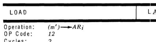
OR
AND
LX
SX
IX
IIC
TC
RC
TPE
RPE
TIO
TW
TR
TOV
TOP
RIO
RW
RR
AI
PI
JIP
LC
LWC
LRC
NOP
SC
SCJSL
SWC
SRC
ST
SRT
SWT
HJ
RCK
WD
RT
WT
AT
August 22,1962
The mnemonics for machine operation codes as printed in this manual are
considered acceptable but non-standard by UNIVAC.
This means that the
UTMOST orocessor will accept programs written using either this set of
mnemonics or the standard UNIVAC III set.
The following table gives the relationship between standard and non-standard
mnemonics:
SALT
UTMOST
SALT
UTMOST
(standard)
(non-standard)
(standard)
(non-standard)
L
LA
ERS
AND
LCS
LAN
LX
LX
EXT
LF
STX
SX
ST
SA
IX
IX
STCS
SAN
ICX
IXe
SZ
TCI
TC
A
DA
ReI
RC
S
DS
TPE
TPE
AH
DAH
RPE
RPE
SH
DSH
TIO
TIO
M
DM
TW
D
DD
TR
BA
BA
TOV
BAH
BAH
TOP
BS
BS
RIO
RIO
BSH
BSH
RW
SR
DSR
RR
SL
DSL
AIO
AI
SAR
ASR
PIO
PI
SAL
ASL
TIOP
JIP
SBC
BRR
IOF
LC
CA
CM
LWC
C
C
LRC
OONE
CPA
NOP
NOP
CZRO
CPZ
STMC
SC
T~
JE
TR*
SCT
THI
JG
SL
TLO
JL
SWC
TPOS
JP
SRC
TUN
J
STCR
ST
TR
SLJ
SRT
SSI
SS
SWT
RSI
RSWAIT
HJ
TSI
JS
LT
RCK
ATD
LAD
DIS
WD
DTA
SAA
RT
RT
ZUP
LAE
WT
WT
SUP
OR
ACT
AT
UNIVAC III
UTMOST , U- 3520
UPDATING PACKAGE A
CONTENTS: SECTION II , nages 3-4,9-10,21-26,29-34,37-55
SECTION IV , nage 1
SECTION V, Dages 1-4,23-24
August 24,1962
The attached sheets are the first changes to the UTMOST manual.
There are three major programming modifications resulting from the
implementation and testing of the UTMOST assembler:
1. The format of the DO directive (SECTION II, page 32)
2. The specification of a method and format for writing multiple-word
alphanumeric constants useful in typewriter messages and High Soeed
Printer headings. (SECTION II, oage 10)
3. The addition of the COR directive for source code corrections. (SECTION II,'lage 41)
Read these carefully.
UNIVAC III
UTMOST, U-3520
UPDATING PACKAGE B
OONTENTS:
INDEX
, pages 1-3
SECTION I , pages 1
SECTION II, pages 5-8, 11-12, 15-20, 29-30,
SECTION III,pages 1-4,9-10
SECTION V , pages 31-32, 49-52,63-64
Appendix 1, page 1
October 1,1962
33-63
The attached sheets are additions and changes to the subject manual.
There are three additions of major importance:
1. The modes of the results using operators with items of mixed modes is
specified in SECTION II, pages 17a and 17b,
2. In the reference section, SECTION III, the levels of the operators
are specified.
3. Appendix 1 contains the error codes that are used and appear in an
output listing of an UTMOST
as~emb1y.The two PROCs, the
$
Editing PROC and the MOVE PROe, have been assembled
and tested. The output listings of the assemblies and tests appear in
SECTION II, pages 33 and following.
Other changes are minor in nature.
UNIVAC III
UTMOST, U-3520
February 1, 1963
UPDATING PACKAGE C
CONTENTS:
INDEX
SECTION I
SECTION II
SECTION III
SECTION V
Appendix 2
pages 1-3
page 1
pages 3-12, 15-42, 53-58
pages 1-6, 9-10
pages 23-24, 29-30, 33-48, 51-54, 69-70
pages 1-10
The attached sheets are additions and changes to the UTMOST manual.
There are five major revisions:
1.
The addition of the GO directive (Section II, page 40).
2.
The addition of the NACL directive (Section II, page 41).
3.
The addition of Binary Card Formats (Appendix 2, pages 1-10).
Read these carefully.
4.
The deletion of the COR directive from the UTMOST
assembler. (See SUPPORT III, UPCO, ACCO and
DECO).
5.
Delete the operating procedure; this will be revised at a
later date. (Section IV, page 1).
I SECTIDN.
UNIVAC
m
UTMOST
r REVISION:
I 1
1-~~~~~k't~~-i,-19c)~ ---t,-:,-~~-~;
I I
- !
1TABLE OF CONTENTS
1.
INTRODUCTION
1-
1II.
BASIC INTHODUCTION TO UTMOST
ASSEr~IBLEHLANGUi\GE
11
--
I1.
Computers and Languages
11-
12.
The
UTIVIOST Assembler
11 ._,:::
3.
Symbollc Coding FOI'll1at
II _. :2a.
Label Field
II -. ,)b.
Operation Field
II - .JII _. ' J
c.
Operand Field
d.
Line
Control
II '- I;4.
Expres sions
i! -- 7a.
Elenlentary Itenls
11
- 'ib.
Operators
-,c.
l'v'Iode
r
15.
Data Word GBneration
11
... 1 ' .a.
lCW, Increnlent and CornpareWord
11 .- Jb.
TWC, Two Word Constants
-
1c.
+
or -
Operation Fields
l1
6.
Mnelnonic Instructions
U 1'17.
Line !telns
II ,,- '" r' OJ-.1+,)
,:1 ., . -~ • j
8.
Asselllbler Directives
a.
EQU
11 -"'~ :::bU ,J
--b.
HES
c.
USE
II 2','d.
FOHNI 11 .-.:.:
~"-e.
SET
II :;(12 SECTION:
Index
UNIVAC
m
UTMOST
DATE: PAGE:
Feb. 1, 1963
2TABLE OF CONTENTS (Cont'd)
g.
END
II - 31
h.
DO
II - 32
i.
PROC
II - 33
j.
NAME
II - 35
k.
Procedure Reference Lists
II - 36
l.
GO
II - 40
m.
NACL
II - 41
9.
Sample Problem
II - 41
10.
Sample Floating Dollar Sign Editing Procedure
II - 44
II.
Sample MOVE Procedure
II - 56
III.
PROGRAMMER'S REFERENCE GUIDE
III -
1A.
Line Control
III -
1
B.
Label Field
ill -1
C.
Operation Field
III -
1
D.
Operand Field
III -
2
E.
Expressions
III -
2
F.
Mnemonic Instructions
III -
5
H.
Line Item
III -
5
1.
Addressing
III -
7J.
Assembler Directives
III -
7K.
Procedure Reference Line
III -
11UNIVAC
m
UTMOST
I REVISION:
I
SECTION:I 2 I
I
---1-
Index
~E:
I PAGE:I
Feb. 1, 1963
I
TABLE OF CONTENTS (Cont'd)
IV.
OPERA TING PROCEDURES
IV -
1
V.
UNIVAC III CENTRAL PROCESSOR
V - I
VI.
BOSS III COMMUNICATIONS
VI -
1
VII.
MNEMONIC INSTRUCTIONS
VII -
1
Appendix
1 -
Error Codes
Appendix 1
UNIVAC
m
UTMOST
Notes
DATE: PAGE:
~-I
!
I REVISION:
2 I
SECTION:
I
UNIVAC
m
UTMOST
~-.-
--+---_._---_._--I DATE: PAGE:
I
Feb.
1, 1963I
1.
INT RODU eTION
UTlVIOST @NIVAC THREE lVIACHINE ORIENTED .§.YIVIBOLIC THANSLATOH) is
an easy to learn and easy to use assembly language designed to permit rapid
efficient coding for UNIVAC III. UTMOST is
atwo-pass assernbly system
pro-viding rapid translation frOl1l synlbolic to object coding-.
The UTMOST system contains a wide and sophisticated variety of operators
which provide the ability to fabricaLe fields during' assembly without restrictions
on the progT:lmmer. The n1nemonic operation codes describe nlachine functions
and
prevent the progran1Jner from having to learn a wide variety of octal fnachine
codes. The system has a series of twelve assen1bly directing instructions which
1
aid gTeatly in pron1oting easy c0l11munication with input-output and executive
~3ysterns.In addition, the assernbly directives provide the programn1er with the ability
to vvrite
short routines which are variable at assembly tin1e. These routines and standard
routines are
eas,)" to incorporate in the program, thereby reducing the effort of the
progran1l11er and increasing prog;ranlJning production.
UTlVl()ST produces relocatable binary output
ina card forln suitable for processing
by a binary card loader.
Italso supplies
alisting of the original symbulic codi
ngtogether with an octal representation of the word generated. Certain error flags
are also supplied in the listiu?
The UTM OST
]11anual is in ;::;cveral sections. Section II is designed to aid the
I
REVISION: SECTION:Notes
UNIVAC
m
UTMOST
DATE: PAGE:
REVISION: SECTION:
UNIVAC
m
UTMOST
DATE: PAGE:
July 1, 1962
II. A BASIC INTRODUCTION TO THE UTMOST ASSEMBLER LANGUAGE
A. GENERAL
1.
Computers and Languages
In order to solve a problem, a computer must be given a series of
instructions which determine how the computer is to operate. In
addition, the computer must be given one or more sets of data upon
which to operate. This combination of instructions and data is called
a program. A program must define in complete detail exactly what
the computer is to do, under every conceivable combination of
cir-cumstances, with the data which is read into or processed by the
computer. The number of instructions required for the complete
solution of a problem may be a few hundred or many thousands,
depending upon the problem. The computer may refer to these
instructions one after another.
Itcan also be instructed to repeat,
modify, or skip over certain instructions, depending upon
inter-mediate results or circumstances. The ability to repeat operations,
usually called looping, combined with other facilities of modifying
and skipping over instructions, permits a significant reduction in
the number of instructions required to perform a given job. For
example, two sets of numbers exist and it is desired to add the
corresponding numbers of each set together. Instructions may be
written to add the first number of the first set to the first number
of the second set, then to repeat this operation with the second, third,
fourth, etc., numbers of each set.
In this way, a few instructions
may cause thousands of additions.
Since the computer __ does not respond to the English language, the
program must be encoded in a form known as machine language.
Considerable time and effort have been expended in developing
programming systems that allow the programmer to write in a
symbolic language more easily comprehensible to him than machine
language. Associated with a programming system is a machine
language program called a processor. The processor accepts a
program written in the symbolic language (source program) and
converts it into a machine language program (object program). The
symbolic language utilized to program for UNIVAC III is known as
UTMOST C!Lnivac Three Machine Oriented
~mbolicTranslator).
II
UNIVAC
m
UTMOST
II
DATE: PAGE:
July 1,
1962
2
====================================================================================
2.
The UTMOST Assembler
The UTMOST assenlbly program was designed to provide a programmer
with an easy to learn and easy to use assembly system. UTMOST is
a straightforward data processing program, accepting input data
(sylnbolic coding) and processing it and producing as system output,
object coding usable by UNIVAC III directly.
As the sylnbolic coding is processed, the UTMOST assembler tallies
the nun1ber of lines produced in a location counter. The location
counter can be referenced by the programmer in his symbolic coding
and may be utilized throughout his program. UTMOST also provides
the programmer with a series of
roperators
rpermitting hin1 to
fab-ricate any object code values which he may need. A small number of
extreniely powerful assembly directives are also made available which
allow the programmer to direct the assembly in an extremely positive
manner during the actual assembly. In addition, the programmer
may use mnemonic operation codes which explain machine functions
by their very nature rather than having to learn the machine code bit
configurations.
The UTMOST assembler provides output in the form of a loadable
object program plus a listing of the symbolic program arid the object
program. The listing also provides the programmer with error flags
at whatever points the assembly system detected the errors.
In the section following, each feature of the UTMOST assembly system
is exalnined in detail with examples of each operation, as well as an
illustrative problem demonstrating a legitimate approach to the
solution of a simple data processing problem for UNIVAC III utilizing
the UTMOST language.
3.
Symbolic Coding Format
I
REVISION: I SECTION:UNIVAC
m
UTMOST
DATE-:----2
- - -
--~-
PAG;II_
-PROGRAM
I
Feb. 1, 1963
iIn writing in UTlVIOST language, the progralnlner is not bound by a
fixed length field concept as is the case with older assenlbly languages.
All
of the fields in UT1VI0ST are in free form, and are designed to
provide the greatest convenience possible for the progralnrner.
PROGRAMMU< OATE _____ _ _ _ PAGE ____ OF __ P .. GES 1 LABEL 6 OPERATION OPERAND COMMENTS
'II
:,!,'I~
l i l t ! I j j I IJ II I
Iii
j 1 I ! : II I!
I
I Il
I I I I jI ! j I I I I I 1 I I : I 11; I 11 J ; II [ I! ! !
i : i j l ~ 1 l I i . l.
I I ~ : J i 1 ! ! ; 1 I 1 I
I
1 JI
I
I I
I I
1 I I I 1 I i I I j : I I I I i I 1 I I I j ! 1 '
J L j j J 1 i , I
'i
I I I I I' I I Ji " I 'I I
J i ! . ! I I i I I I I' j I ' i I I I . " I i
l I I I I I ~ I I I I ; 1 I I ! I I I I 1 I I ,
I i I I I
j ~ 1 1 i
1 I i I 1 I , I i J
~~'~i~,~-I~1 ~I ~~I~,~I~"I~I~1 ~~~~~~_lJI~_L_LLL_LL~~LL~~~~~_L~~~~~~~+I~I~~~~
_Ll 1 [I 1 I _ LJ I I I j J
.1 L I j Ll j
l L L U
I
..L.L..LL.Li
L: I
II
I 1 I I i II
I : jL
I i i i I I I I j L II
L ! 1 I I : [ l.: i ~_ l ~ l 1 L.1 L _I1Ll
I jII
11 j, : I I ! i i i J "l
I 1 j ! I I ! j ! I : I I 1 1 1 ' 1 1 1 I i I [ I I : 111:::i
:~:
I
I j L
~
il_~
[ j 1 ! I I L I J I I LJ i i i I J ! j I i i I I 1 1 i i i L 1 I I I ,I ! I 1 t L [ . 1 1 I I j 1 ! I j
I i II ! t I , 1
I
J I II
j I I j 1 I Il
j 1 II
j I !!
! .~ Li i I I I I j L I :I
u_~ II I i i I'I'ILLD-.J
I [ iLl 1_ [1 I I J j 1 I I j
J J i 1 \ l l I
a.
Label Fie lel
A
label is a method of identifying either a synlbolic line of coding,
or a word of data. In writing a label in UTMOST, the prograolmer
rnay use any 111eaningful conlbination of one to sixteen characters.
Of
these sixteen characters, the first Blust be an alphabetic
(A •• • Z),and the others,
ifpresent, may be either alphabetics or nUlllcrics
(0-9).
Sample labels are listed below:
PRNT
ONE
A
ARRANGE
ADOL
OVER2
In
writing a label in the label field of a symbolic line, the first
character of the label must be left justified within the line and
the field ternlinated by a blank. There Inust be no blanks within
the label field itself. No special characters may be used in
a
2
UNIVAC
m
UTMOST
DATE: PAGE:
Feb. 1, 1963
In the symbolic lines illustrated above, each of the labels in the
label field, OVER, ONE and ARRANGE follow the requirements
of the label field. Each starts with an alphabetic in column
1,
is from one to sixteen characters in length, and is terminated
by a space.
b. Operation Field
The operation field of a symbolic line informs the assembler of
the purpose of the line. An operation field may be up to sixteen
characters
inlength, and may contain a mnemonic machine
operation code,
an assembler directive, a label associated with
a FORM NAME or PROC directive or a data generating code.
Each of the above categories will be discussed in detail in its
appropriate section.
An entry in the operation field is terminated by a blank unless
it
is a plus or minus sign, in which case the operand field may
begin in the succeeding column.
If the line does not have a label,
the operation field may begin in the second column of the coding
fornl.
II
4
UNIVAC
m
UTMOST
I REVISION: 1
~---.
----I DATE: Oct. 1~
I SECTION:
----1----18()~ PAGE:
I !
LABEL 6 OPERATION OPERAND
-_lJl£UL.JJilJJJ
lS',
Jl~
Sl
-L1Ll LL
jlClMl~l1J5"-9-J ~_L~J_
l-J.J-.L1_J __
L
jL~JRIE-19LLL-.l~
__
LJJ_l-LL.L __l
--.LU.l-LllL~lELJ_I~_Ll_~J-J3LU_l
I I ' I '
L 1
Ll
1
1
J1
j 1
l
1J
j I.J
1
j
jj i I
i
Ll
In the illustration of operation fields above, Line 1 contains an
operation field LA following the label ONE.
Line 2 contains an operation field, ClYI, starting
in columll2,
showing that no label is present.
Line
3contains an assen1bler directive as an operation fie
lei,RES.
Line 4 also contains an asselnbler directive in the operation
field, USE.
Note that each operation field follows the rules staLed above.
c. Operand Field
The operand field of a sY111bolic line follows the label and
opera-tion fields. It consists of one or Inore expressions defininf,!;
theinforlnation required by the operation field of the line.
Expressions within the operand field are separated
by ('Ulllllja~.and the COlllITla indicates that anotiler expression follows;
'1'C1'-rnination procedures are discussed under Line Control, beiuw.
The maximum nun1ber of expressions on a line is determincd
11j-the content of 11j-the operation field of 11j-the line. However,
,-Ul) linl'Jnay contain less than the maxin1un1 nUlnber of expressions
indicated by the operation field; so long as it has at leas tunc'.
The unwritten expressions will be assUlned by the asselnlJler
Lobe zero.
JI
UNIVAC
m
-)
...
UTMOST
DATE: PAGE:
Feb. 1, 1963
LABEL
!l.
OPERATION OPERANDIn the examples, the
0following LA represents a single
expression in the operand field. The second line of syn1bolic
coding represents a three expression operand field, each
expression separated fron1 the previous one by a comma.
II
6
d. Line Control
TLe inforrrlation content of a line to the assembler consists of
a label, operation, and operand fields. The information content
is normally terminated when the maximun1 number of expressions
required by the operation has been encountered (or the nlaximum
number of lists in the case of a procedure reference) or by the
end of card, whichever applies to the case in question. There
are two special marks which override the normal rule:
1)
Continuation:
If
a ";" is encountered outside of an
alpha-betic item, the current line is continued with the first
non-blank on the following line and there is no n10re information
to the assen1bler on the line in which the ";" occurred.
2) Termination:
If
a "." followed by a blank is encountered
outside of an alphabetic iten1, the line is terminated at
this point.
If
additional expressions are required by the
operation field, they are assumed by the assembler to be
zero.
I REV/SION: I SECTION:
r
UNIVAC
m
UTMOST
~
1 __
----II---~I
__
DATE:
Oct. 1,
191;2 PAGE:LABEL
A
OPERATION
OPERAND
f.!'!!JLJr..a.Lil!-.l..J!!!!L_~LLlL~LL~LLJtiLJ_-lj
JJJ
I
I 1~~--L¥.
----L-L-LlLLl
LLL1Ll_ll_
LLLJ
LJ J1
'-11cl'1f'
IJ __
u_Ll-LLLL1-~LL
L
J
_I
Lj
L
j
j 1 J, I
I
I I I_Ll_Ll_Jl_-LL1U
Ll
j II
II
i I I!
The s81nicolons indicate that the line is continued on the next
line. The assenLbler would treat the three lines as though
they were the following line.
! ! ! ! I ! ! ! ! ! ! I ! ! I I I ! I I I I i
7
~1llIl'J'~~_~-L
Ill)
I~t,tl L~_~LL1-LLll_L_LJ
mL
1 _-L1JLL1J_lJ
J LJJ
j
I I1
I IJ
1; L_l~
1
ILl~~1~-LL~LLl~-LJ_LL~JL_L_1LLLLL_I~_111
I l LLl!
1 1i
l_1 II
J I I L [1_ElY
1'lalRla
111)~''f!.1 (TiHd!I_l~~lt;LjZ1h_IU:lR!~W~ITl£lDJJ8JYL t;Wl£ll1E~9JjI 13PJ81<l~
Ilrsl
1l.IZIMSJrJSl" ILlSlol
J_w~lr~JDl JslYLLLWL~
__
~~1Ik11D.
dNJClli
-1
I i i 1 iThe three lines above use
a period followed by a t>pacc to
ternlinate the lines. Any infor Ination following the period
space is considered to be a comnlent and will be printed on
the symbolic output listing. The assen1bler will take
nuaction on the infornlation following the
~eriod.4.
Expressions
An expression is an elenlentary itelll or a series of elernentary
itenls connected by operators. It nornlally appears in the operand
field Jf a sYlnbolic line.
a. Elenlentary !terns
UTNIOST permits the utilization of a series of elenlentary
items which may be used in expressions.
I
REVISION' SECTION:1
II
UNIVAC
m
UTMOST
DATE: PAGE:
February 1, 1963
8
======================================================~====================~============~--noted under Label Field), it is assigned the current
value of the location counter. Thereafter, when it is
encountered within an expression, the integer value
initially assigned to
itwill be substituted for the label
within the expression .
. . . I
. I . I . . I .. , I , . .In
the example
above~AR1 will be loaded with the value of
the label CONST, which is a decimal 24.
2}
Location:
The current value of the location counter may be used
as an elementary item within the operand field of a
sym-bolic line. The format of a reference to the location
counter is the dollar sign
($).When this sign appears
in an expression, the value of the location counter is
substituted for
it.It is useful in reflexive addressing.
In the example above, if the current value of the
loca-tion counter was 5280, the integer value 5280 would be
produced as a one word constant in decimal, right
just-ified, with preceding binary zeros and a positive sign.
3) Octal: Octal values (base eight) may be represented in
REVISION:
UNIVAC
m
UTMOST
DATE:
Feb. 1, 1963
-L~J.J4)JlJ1'i.L.LlJ~
...
L1
J.1 1..1..1 .. LJ.1l
_.L~_.LLJ_L.LJ_.L J-.J~Ll.1
LL
JL L11.
L ilL-L.LLJ ..
l.QwdaLlL-L~LLL
L J_l. J..J.J_.L l.LJ J.In the exalllpies above:
OJi is
equivalent to
07007
isequivalent to
000 000 000 000 000 000 001 111 000 000 000 000 III 000 000 III
in
their
con\Tcrtc"dobject code.
4)
Decjmal: Decimal values
maybe used as elementary
items
within anexpression. Where they appear, decimal
values (base
10)will be converted into their
binaryequiva-lents and rig-ht justified within their oI)ject Jiehis. A
decimal item is representeci as a nOll-zero
dif.;.'itfollowed
by
decimal
(O-~»)cUgits.
.J~L
I
I!91.li.
I II
I~_Ll
I/IO~J~LLLJ_L_.L_Ll
In
the exarnples above:
~) is
equivalent to
102<1
is equivalent to
, , I , I I
I
000000000000000000001001 000000000000010000000000
G)
BCD:
UNIVAC III binarycoded decillla1 excess
three
values in four bit notation
maybe utilized in elementary
items
bypl'ececiint4' the value with a colon (:).
'-"11cn a
decin1al value appears
inthis forn1at,
itwjJl be
trans-lated
bythe assenlbler into its corresponding
,Ibit base
lG
value and riglltjustified within its field.
:8 is equivalent to
: 1024
is equivalent to
I
2
II
UNIVAC
m
UTMOST
~
-PAGE:
Feb. 1, 1963
10================================================~================~==========:==~=
G) ~_!Q!1abetics:
(a) Six bit alphabetic characters may be
represented in an elementary item by enclosing the
de-sired characters \\'ithin apostrophes ('). Since the
assen1blcr recognizes an apostrophe as the end of the
alphabetic value. it is not permitted to use an apostrophe
within the alphabetic grouping. The six bit object code
result ing from an alphabet ic item w ill be right just ified
within its field and preceded by binary zeros (space
codes). Alphabetic items used as literals will produce
the forn1at described above.
_LU~LLLLJ_L_J~_LLLJ-Ll.-L.LL _
~_l~~tllllLLLJ_LLJ_LL
In the exanlple above:
'PAGE' is equivalent to
'Z' is equivalent to
101010 010100 011010 011000 000000 000000 000000 111100
(b) A multiple word item (maximum 78 characters) may
be generated in six bit notation by enclosing the desired
characters within apostrophes. The resultant object
code will be left justified. The left hand apostrophe in
this case functions as an operation code.
~L-L-1--,I..-LL1_~-.LlU_L~.-LJ-LLL.L_LLLJ_L_,.J. __ L.LLL I _L_LL.LLLJ _L_LU_-.Ll.~~_LLJ ___ LL-LlL~ L-I L-I L - L - ' - - '
~~",----,--,-,----"",",""-,-""---,,,,,,,~lLu~.l-.l~l_LLl L UJ~_LLL1.l~_I_LU~LLh-L_LLLLJ~J ___
Ll-,I---,I--L-'---L-~LJ-J.-"le"""-1J'&MlrL~eIRI ICloIQi.1 LLJ8.U18JcJH~lXl.\'lG\ 1 I ~LslZ.Ii¥1 1 .-LJqIUIRltmirlljYLLL-WL--+PJI'~'
I I I '
In the above exan1ple:
'FILE ID' will generate the following bit pattern for the words:
011001 011100 100110 011000 000000 011100 010111 000000
7) Floating Point Nunlbers: Floating point nUlnbers may be
represented within an elementary expression by including
a decimal point (period) within the desired decimal value.
The converted value will be in standard UNIVAC excess
50
floating point format with a ten digit mantissa and a
two digit characteristic.
I : : :
i:~:.:l~:
: :
i : : :
I ; ; ;
i
;L
I I I I
In the example above:
REVISION:
2
I
SECTION:I
II
UNIVAC
m
UTMOST
DATE:
Feb 1, 1963
t
-I
PAGE:
S)
Field: A field rnay be referenced as an e lClYtental,)
expression
bywriting a field label followed by an
expres-sion enclosed in parentheses representing the address
of the partial word. The field iten1 is discusseJ in
greater detail in the section on Assenlbler Directives,
FLU
directive.
_.L_LJ~lXLL t!lYJAJLILlIsl)L-l~_J
_LLJI
In
the exarnple above:
11.
EXT
represents the bit control pattern for field selectiun,
(VALUE) represents the location frOITi ',;vhieh the field
will be selected.
~)
Param.eter:
Aparameter rnay exist as an elementary
iteln by following the procedure label with one or two
expressions enclosed in parentheses. The paral11eter
it81ll
is discussed
indetail under Assenlbly Directives,
PROC
directive.
10)
Line: An entire line ll1ay exist as
311elenlcntary item by
enclosing the line within parentheses. The asselnblel'
will generate the value of the word that tile line would
generate
if
it existed as a separately coded line.
~~~-~(:~~:~~~;:) ~; ~~~
. .:
.~. ~
.•
~
.• , I
I
I I II ,
I II
I I II
I I IIn the above exaluple:
(' DON') would generate the constant DON in six bit
alphabetics preceded by binary zeros in the saIne
rnanner that tDONt would on a symbolic line
byUNIVAC
m
UTMOST
tVISION'
SECTION:I DATE: PAGE:
July
1, 1962
b. Operators
An expression nlay consist either of an elementary itenl, or a
series of elen1entary itellls connected by operators as shown
in the table below:
+
Arithrnetic Sunl
*
I
++
**
II
>
<
*+
*-Arithnletic Difierence
Aritlllnetic Product
Arithmetic Quotient
Logical SUln
(OR)Logical Difference (EXCLUSIVE
OR)Logical Product (AND)
Covered Quotient
(allb
=
a+b-1)
b
Equals
Greater Than
Less Than
b
a
*+b
=a*10
-b
a *-b
=a*10
1) + Arithn1etic Sum: The arithmetic sum operator Dlay be
used to conlbine two or lnore items. The assembler will
sunl the integer values of the items and the resultant
integer value will be utilized in the resulting expression.
~~
L
Itl IIziti31 I
I
I~L11u~Lu~u
1
J_Jtbu~_Ll~J~~LLlu~J_1
LLl
• I I I I I I
In the above examples:
7
+
3 would produce the integer 10 in binary.
$
+ 15 would produce the current value of the location
counter incremented by 15 in binary.
2) - Arithmetic Difference: The arithmetic difference
operator may be used to subtract one itern from another.
The assembler will subtract the integer value of the
second item frolll that of the first, and the resultant
integer difference will be substituted in the expression.
II
REVISION: SECTION:
UNIVAC
m
UTMOST
DATE: PAGE:
July 1, 1962
In the above examples:
$ -
3 will produce the current contents of the location
counter less three.
VALUE - 10 will produce the integer equivalent of the
label "V ALUEn minus ten.
7 - 4 will produce the integer three.
3)
*
Arithmetic Product: The arithmetic product operator
may be used to tnultiply one item by another producing
the arithmetic product. The assembler will multiply the
integer value of the first item by the integer value of the
second item and the resultant integer value will be
sub-I
~:ti~~;~~
F
:e~::S~i:T
I : : : :I I I I I
In
the above examples:
7*3 will produce the integer value 21.
II
13
$*2 will produce an integer value equivalent to the current
contents of the location counter times 2.
UNIVAC
m
UTMOST
IT
DATE: PAGE:
July 1, 1962
14
I I
I
II ,
I ,I , .
In the above examples:
44/4 will produce the integer value 11.
$/1024 will produce an integer value equivalent to the
number of possible index registers required for area
addressing in the program up to this point in the program.
33/2 will produce an integer value of 16 (remainder has
been discarded).
5)
++
Logical Sum (OR): The logical sum operator (OR)
may be used to logically sum the binary equivalents of
two items. The assembler will logically add the two
values and the resulting logical sum will be utilized in
the expression.
In the above example:
, A'
in six bit code is
010100
'3' in six bit code is
000110
Logical sum generated 010110
UNIVAC
m
UTMOST
~_EVI_S_IO_N_:
_ _ _ _ _ _ __
~CTIO-N--n
_ _! DATE: I PAGE:
July 1, 1962
! lr: .)~
LLLL_LlLLLLd_LLLLLLLLLl_Lj
1L1
___
rtiJJ~~1:~rl~~L_L_LLL_LJ_LJ.L.l
LI
1 II I I , I I
In the above exarnple:
'V' in six bit
codeis
'T' in six bit code is
Logical difference is
111000
110110
001110
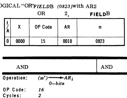
7)
**
Logical Product (AND):
The logical product operator
may be used to AND (Logically multiply) the integer
value of one itern by another. The assenlbler will logically
nlultiply the two values and the resulting logical product
will be utilized in the expression.
~U_LJ..LL
L
1.
LLJ_U
J.1J.~J.
LLL~I
I ft.! II\I"(!~\!T!/I
I
I I II
I IIn the above exaulple:
'V'
in six bit code is
'T' in six bit code is
Logical product is
I I
111000
110110
110000
a+b-l
8) / / Covered Quotient (a/ /b
=
b
):
The covered quotient
operator rrlay be used to divide the integer value of an item
by the integer value of a second itern or expression. The
effect is the salne as adding one to the integer value of the
quotient in straight division (A/b)
if
there were a rernainder.
The resultant integer will be utilized in the expression.
~
*llt.--U-lL.-Ll_Lu.
I I
iI.
I I I
"1-ISl7~
1&7tJ
lLl1l1lol~,~l~_L
I I I
I
I I •I . .
I . I IIn the above exan1ple:
2
UNIVAC
m
UTMOST
DATE: PAGE:
Feb. 1, 1963
9)
=
Equal: The equals operator may be used to compare
the integer values of two items or expressions.
If the
two integer values are equal, the value of the resultant
field is a binary
1.
If the two integer values are not
equal, the value of the resultant field is a binary
O.
I:::~~~:::::r::::
I I I I
In the above example:
If
$
=
7083, the value of the expression is binary
1.
If
$
~7083, the value of the expres sion is binary
O.
10)
>
Greater Than: The greater than operator may be used
to compare the integer values of two items or expressions.
If
the integer value of the first item or expression is
greater than the integer value of the second, the value of
the resultant field is a binary
1.
If the first value is less
than or equal to the second, the value of the resultant
field is a binary
O.
I : :
~:~o~J~
: : :
r : : : :I I . I . . I . ,
In the above example:
If
the value of AMOUNT is greater than 2, the expression
value is binary
1,otherwise it is a binary
O.11)
<
Less Than: The less than operator may be used to
compare the integer values of two items or expressions.
If the integer value of the first item or expression is less
than the integer value of the second, the resultant field
value is binary
1.
If the first value is greater than or
equal to the integer value of the second, the value is
binary
O.
II
16
-I REVISION:
I
SECTION:UNIVAC
m
UTMOST
I
, 1 I
\ II
~---
----
-i---DATE: PAGE:
Feb. 1, L96;{
In
theabove exanlple:
If
the value of COUNT is less than 5, a binary 1 will be
generated, otherwise a binary 0 will be generated.
12) *+ Positive Exponent: The positive exponent operator
may be used to create a two word floating point CUllstant
in excess 50 notation where a *+b is equivalent to a
*
lOb.Both words must be excess three binary coded decirnal
nUlllerics.
In the above exanlple:
: 10. 0*+: 15 will produce 671000000000
13) *- Negative Exponent: The negative expunent operator
is similar to the positive exponent operator in that it
will produce a floating point word in excess 50 notation.
In the above exanlple:
:15.0*-:3 will produce 491500000000 as the integer
equiv-alent in standard UNIVAC excess 50 floating point £orn1at.
17
In all of the foregoing cases where items are connected
by operators,
ifUNIVAC
m
UTMOST
I REVISION'
3
II
DATE: PAGE:
17a
Feb. 1, 1963
c.
The mode of each item within an expression can be
different. As the assembler evaluates each item a
determination of the mode of the result is made. The
determination is contingent upon the operator used, as
well as the mode of each item within the expres sion.
The operators are listed below grouped by function:
GROUP
A
B
C
D
OPERATOR
++
**
+
*
I
II
* ...
*-DESCRIPTION
Comparison
Comparison
Comparison
Logical Sum
Logical Difference
Logical Product
Arithmetic Sum
Arithmetic Difference
Arithmetic Product
Arithmetic Quotient
Covered Quotient
Positive Exponent
Negative Exponent
REVISION: SECTION:
II
UNIVAC
m
UTMOST
DATE:
Oct. 1, 19G2
PAGE:17b
MODE OF
OPERATOR
IHODE OF
l\[ODE OF
FUlST ITETvI
GROUP
SECOND ITEIVI
HESULT
Any
A
Any
Binary
Any
B
Any
Binary
Binary
CBinary
Binary
Binary
CDecilnal
Binary
Decimal
CBinary
Binary
Decimal
C
Decirnal
Decimal
Any
C
Floating
Floating
Floating
CAny
Floating
I REVISION: SECTION:
1
UNIVAC
m
UTMOST
DATE: PAGE:
Feb.
1, 1963
5.
Data Word Generation
The UTMOST assen1bty system provides three means of generating
data words other than expressions.
These data words consist of
Increment and Compare Words, two word constants, and words with
a plus
(+)or minus (-) operation field. The last category provides
the ability to generate constants, indirect address words and field
select words with or without index registers.
a. Increlnent and Compare WORD, ICW
The increlnent and compare word is used to prepare a word
suitable for increnlenting and comparing an index register
(with the IX and lXC instructions).
The Increment and Compare word is written with lCW in the
operation field of the line, followed in the operand field by two
expressions, e and e . The first expression, e
1,
represents
the comparison
1amounl and the second expression, e
2
,
repre-sents the increnlent. The format of the generated word is
illustrated below:
lCW
In the above example:
lCW informs the assembler that this is an increment and
compare word.
$ +
30, the first expression,represents the
comparison amount;
1,
the second expression, represents the
increment.
b. Two Word Constant Generation, TWC
A two word constant may be generated by placing TWC in the
operation field of a line, and the constant in the operand field.
This symbolic line must have a label. The assembler will
generate the value of the expression in the operand field, right
justify filling with binary zeros the resultant value in the two
word field, and assign an address to the label. The sign of
both words is identical. The left half of the two word constant
IT
REVISION: SECTION:
UNIVAC
m
UTMOST
-
~f--=---~-
II
i PAGE: DATE
rnay be addressed by using the label, the right half by using
the label plus one.
[_1_
LLLL~~LLLJJ-LL
1
LlJ __LL_LLJ
:E1&oL~~lweLJj_
LlOLJ __ LL1 __
Ll_L
L
1
L 1_lJ_lLJ_1Ll L
_Ll--LLl
L_LL1~~_~J
JD~lLLwtcLlL~_~~~
__
llllAJ~Ll
__
LJ
In the above exarnples:
ZERO TWC
0will produce
atwo word constant
of /lillaI')zeros.
HDR
TWC
fPAGE NO.' will generate a header line for
editing purposes.
The first exarnple 111.ay be referenced by
ZERO+-land a two
register indicator in the "a" field of an instruction, the second
by HDR+l, and a two register indicator in the "a" field.
c.
+
or - Operation Field: A
-+or - operation field plus from one
to four expressions in the operand field Inay be used to
g~neratespecific constants consisting of a one word constant of datum,
an indirect address word, a field select word without index
register notation (or implied index notation), and a field
select word with specific index register notation.
2
UNIVAC
m
UTMOST
II
DATE: PAGE:
Feb. 1, 1B63
I 1
~~~~~~~~LL
I
In the above examples:
A will produce a one word alphabetic constant in six bit
ccxie containing the word DATA.
B will prcxiuce a one word constant containing the current
value of the location counter in binary, right justified
with preceding binary Os and a negative sign.
C will produce a positive binary constant containing
the address plus ten of label "VALUE".
D will contain a negative constant in excess three binary
coded decimal notation preceded by binary zeros of the
value" 5280".
20
2) Indirect Address Words: Indirect address words may be
generated through the use of a + or - operation field plus
two expressions in the operand field. The first expression
will be generated as a fifteen bit UNIVAC TIl address, and
the second expression will be generated as a four bit index
register ccxie. The sign of the word will be the sign in
the operation field.
I'
I~';~::;
1 J)A
8
+
I
::';' ";:
~J
1 1'I
I '
I I 1 I
In the above example:
REVISION: SECTION:
2
UNIVAC
m
UTMOST
II
OATE: PAGE:
Feb. 1, 1963
21
3) Field Select W·ords: Field select words may be generated
through the use of a
+
operation field plus three
expressions in the operand field. The first expression
will be generated into a five bit left bit control (plus
binary three) integer indicating the left boundary of the
field to be selected. The second expression will generate
the right boundary of the field, also as a five bit binary
integer plus binary three.
The third expression will generate a ten bit binary address
for the word(s) from which the field is to be selected. The
sign of the generated word Inust be positive.
I : :
~: :/~;:
:;):
:~A:L:~~
: : : : :
I I I I I
In
the above exarnple:
The first expression will generate 01111 (binary 15) as
the left bit control, the second will generate 01000
(binary 8) as the right bit control, and the ten bit address
equivalent to tVALUE' from the third expression.
4) Field Select Words: As in 3, above, a field select word
may be generated using four expressions in the operand
field following a
+
operation field. The first
express-ion will generate the left bit paranleter, the second
ex-pression the right bit parameter, the third exex-pression the
ten bit 'm' address, and the fourth will be used to generate
I~e(~[l~;~§~t±
In the above exalnple:
I REVISION: SECTION:
n
UNIVAC
m
UTMOST
I
OAT:
ugus
:
24,
PA[3E:
1962
22
6.
Mnelllomc Instructions
The UTMOST assenlbly systen1 utilizes a series of mnemonic
instruct-ions corresponding to the octal machine code instructinstruct-ions in object
coding which are recog11izable by the computer. The nlnerrlonic
opera-tion codes describe the funcopera-tion of the instrUcopera-tions, thereby removing
the problelll of learning the octal operation codes, or their binary
equivalents. In some cases, a cOlllbination of octal operation code
and bits in the
AR
portion fornl instructions. Mnenlonics have been
created to save a progranlmer frOln writing or knowing the parameter
AR
bit configuration for niost of these.
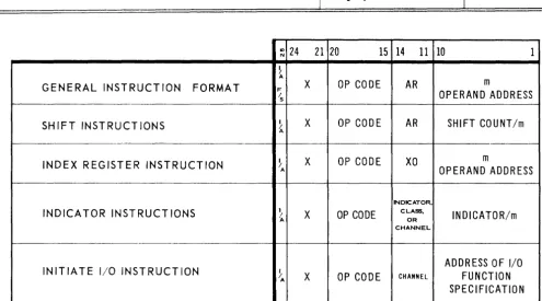
UNIVAC rll's instruction word consists of a 24 bit word with the sign
in bit
25used to indicate either indirect addressing or field selection.
The format of the word on a bit basis is illustrated below:
24
21 20
15 1411 10
S
b
op
a mwhere "b" indicates the index register designator,
"op" the operation code,
"a" the arithnletic register(s) designator, and
"nl" the ten bit area address of the operand.
Since UTMOST provides senli-autolnatic insertion of area index
register assigTIrnents,
itis unnecessary to write a "b" designator
in 111any cases. (See Use Di rective, Section
II,8c)
The order of writing a synlbolic instruction line has been altered
froln the hardware fornlat to provide greater convenience in
pro-gralnn1ing. The fornlat is:
REVISION: SECTION:
2
IT
UNIVAC
m
UTMOST
t - - - t - - - - -------DATE: PAGE:
Feb. 1,
1963
Type 0 Instructions: Type 0 instructions have three fields
repsenting the" aft, "m", and "b" fields of the instruction word,
re-spectively. The sign of the instruction will be
+
unless the "In"
portion of the instruction is preceded by an asterisk indicating
~~c~ :~:r:~;~~~' s~~e:t~::
: : :
I J~'~II;"I:::'M:k:~ ~/:~l
In the above illustration:
23
LA, OR, and SA are mnemonic instruction codes of type 0 category,
requiring in each case the" aft, "mH, and "b" fields. (The "b" field
may be on1.itted,
if
the USE assembler directive has been inserted in
the program prior to the asselnbly encountering these instructions).
Type
1
Instructions: Type
1
instructions have two fields representing
the "m" and "b" portions of the instruction word, respectively. The
sign of the instruction word will be
+
unless the "m" portion of the
instruction is preceded by an asterisk indicating indirect addressing
or field selection.
1---"-""'-'----LII!';UW-l)-Llli-L,
I
I I-1~LU_LI
, ,I , ,
1 __lLl
t----'----'---'--L-Ll~,
I II
ILJ--1_LL1~ll_LlJ
1--1_
~~~L.l!-1J.LL1LI~~~LL
Lll-L_LLL-L II
I I I1--,
In the above illustration:
J is the mnemonic code for the Jump instructions, the first
instruct-ion utilizing direct addressing, the second indirect addressing.
7.
Line Item
A line item is an instruction line, form reference line, or data
word line without label field and without leading or trailing blanks,
enclosed in parentheses.
_~_lJ ll_ll-1_U~LJ~-l~~_LLLU_lliJ
__ I_l_Ll_l-LL_L
,iJAI
Ill)
IIciT,
Ll~J
,I
I I
II
I ,I-L-LLLL_LLW_L
I Lltl
lcal)
I I(IIfIAI4IIC!
I 101) IOI} 10.. 171,IQ11 \01 ..~I", l'lIl1~_L
~LIA
11fi,1 J!J'J1)lo,.I",ll
I
'_-L_L1J_lJJ_-L_LL_ILJ __
LJ __
l_LlI
REVISION: SECTION:2
IT
UNIVAC
m
UTMOST
~---.---~--.---.---DATE: PAGE:
Feb. 1, 1963
In the above exalnples:
LA 1,
(J0)
The last expression is an instruction line written as
line item.
LA 2, (lYIASK 0,0,0,7,0,0,0, 0, 7)
If
MASK is the tag of a form
directive the parenthetical expression is a form
reference line written as a line iteln. (See Form
Directive, Section II, 8d)
LA 4, (,DON')
The parenthetical expression ('DON') is a data
word line written as a line item.
In each case, the assenlbler will generate an address which will be
24
the address of the translated parenthetical expression. The translated
parenthetical expression is called a literal.
If
the literal is identical
to any other literal, the location assigned is the location of the previous
literal, thus elinlinating duplication.
When a line item appears in the address field of an IX or lXC
instruct-ion and has two expressinstruct-ions, it is evaluated as a data word with lCW
in the operation field.
In the above exanlple:
The assenlbler will generate an index register increment and compare
word equivalent to the sarrle expressions in an ICW line.
A literal will be double precision
if
the line was a TWC line or
if
it
was a data line with one expression and the mode of the expression
I
:~ r~;~n~~:~ ::~)
I I II
1 .
li;Li~ii.'/~~~~
In the above exanlples:
The first exalnple will generate a two word constant (double precision)
in BCD forlnat 000000000005.
SECTION:
UNIVAC
m
UTMOST
I
REVISION:I
DA~-E-: ---~-- --+-P-A-I3-E~--~n
.----Feb. 1, 196:3
258.
Asselnbler Directives
The UTMOST assembler provides the progralnmer with a series of
powerful operation codes in the fornl of Assenlbler Directives. These
assenlbler directives do not produce coding in and of thenlselves, but
effectively provide a progranlmed lneans of controlling the process of
assembly.
There are twelve assenlbler directives as shown in the table below:
1.
~.
3.
4.
5.
6.
7.
8.
e-v.
10.
11.
12.
I
t
Directive
EQU
RES
USE
FORM
FLD
END
DO
PROC
NAME
SET
GO
NACL
Purpose
Equate operand value to label field.
Reserve menlory locations.
i
Assign index registers for area addressing.
!Designate arbitrary word fornlat.
Specify Field Selection pattern.
Designate end of progranl or procedure.
Generate designated line(s) of coding.
Generate associated coding
ifreferenced.
Qualify procedural coding.
~
Set index register to assumed value.
Means of transfer within a PROC.
I
Replace an UTMOST ID.nemonic.
UNIVAC
m
UTMOST
r---R_E_V_'S_' C_N_:---t:
CN'~
_ _ _~
_ _ _ _I
PMECATE:
Feb. 1, 1963
26
a. EQU
The EQU assen1bler directive causes the label in the label field
of its line to be equated in all succeeding references in the coding
to the value of the expression in the operand field of the syn1bolic
line. Thereafter, the label n1ay be used in an expression, and
the
assenlbler will substitute for the label the integer value of
the original expression in the operand field of the EQU line.
In the above example:
The four arithmetic register nan1es have been equated to the
binary values utilized in object code to address the respective
registers. After these four EQU directives have been encountered
by the assernbler, the
ARportion of an instruction may contain
the label nanles of the registers, and the assembler will
recog-nize then1 as the associated binary values. Accordingly, coding
referencing these registers could read as follows:
I I I I
II II I l l L l
l--1---=----'----L-~aL...L.L-~~~"""-LAL'f--L-.J...I'-'-lU-LLL1J-LLLl
~~-4-~---'---'--_'______'__1
. 1 - 1 __~I,---,I--,I----+-I~~_W
In the above exan1ple the contents of TEMP will
be loaded into AR1 and the contents of TEMP
+1
will be loaded into AR3.
b.
RES
The RES assembler directive causes the value of the expression
in the operand field to be added to the location counter.
It may
be used to reserve a specific or variable number of locations
for input/output storage, or any other programmable purpose.
UNIVAC
m
UTMOST
In the above exalnple:
The RES directive will cause 32 words of storage to be set
aside (32 will be added to the location counter). These 32 words
are equivalent to the
~32words or
128
charaeters required for
one line on the High Speed Printer.
_LL~J~_LL LLL~_.u_LL1_1-LL_Ll.LJ_J
L_Ll
j
LLJ
~'-Ll$~£gllljTJdLgl~~J±116i=LLL
_
Li
if
R
I
IThe two synlbolic lines reference words
15
and
16,
and
:31 and
32 in the reserved area respectively.
c. USE
The USE assenlbler directive is utilized to load index registers
with base values relative to the value contained in the location
counter at the time the USE directive is encountered by
the
asse111bler. After a USE directive is encountered,
itis not
necessary to indicate index register designators in the operand
field of a synlbolic instruction line, since the assembler will
insert the values autonlatically, unless a specific index register
is desired by the programmer.
The USE directive, when encountered by the assenlbler will
assib'11 the current value of the location counter to the first
index register specified in the operand field of the USE line,
the current value plus
1024
to the second, and so on through the
number of index registers specified in the operand field of the
line.
UNIVAC
m
UTMOST
In the above
eX~llnple:Assu111ing that the location C01.U1ter reads 4000 at the till1e the
directive is encoWltered:
ill
5 will contain the value 4000, IR G
will contain 5024: and IR 7 will contain 6048. IR's 5, 6, and 7
will autornatically be inserted into object code where required
by the prograrn, and no indexing has been specified by the
sy111bolic coding.
d. FORM
The FORlVl asse111bler directive may be used to define arbitrary
word forrnats, label these fornlats, and thereafter reference
the fOTll1at by using the associated forn1at label as an operation
code in the operation field. When the assernbler encounters a
FORM directive,
itnotes the pattern specified in the operand
field. Thereafter, the expressions in the operand field of the
associated label, appearing as an operation code, will be
inter-preted and generated in the "form" specified by the initial
directive.
REVISION: SECTION:
UNIVAC
m
UTMOST
1DATE: PAGE:
August 24,
lS62
In the above example:
The FORM directive has been used to define an object code
format equivalent to a UNIVAC III instruction word. When INST
is encountered by the assembler in the operation field of a
symbolic line, the expressions in the operand field will be
generated into a sign bit, 4 bit lib" field, 6 bit "op" field, 4 bit
"aft field, and a 10 bit "m" field.
I I I
I
I I II
I I IIn the above example:
The FORM directive has been used to provide a sirnple means
of writing a masking constant in octal mode equivalent to a
UNIVAC
ill
word. Whenever the label MASK appears in the
operation field, the assembler will generate the appropriate
masking constant. As illustrated in the second line above, the
use of MASK in the operation field followed by the expressions
0,0,0,7,0,0,0,0, 7 will generate a masking constant in the
following pattern:
+
000 000 111 000 000 000 000 111.
II
3
UNIVAC
m
UTMOST
DATE: PAGE:
Feb. 1, 1963
In the above example:
The FORM directive has been used to define a printer control
word. The first example below the form directive will generate
a line of object code which will cause the paper to be spaced
5
lines, and printing to take place from octal location
1004
through octal location
1035.
The second example will cause the
paper to be spaced
2lines. The third example will cause the
generation of a line which will cause the paper to be spaced
6
lines, and printing to take place from the location specified by
the RES directive. In all cases interrupt is specified.
e.
SET
The SET assembler directive may be used to arbitrarily indicate
to the assembler that a specific value should be assigned to an
index register for assembly purposes. The value assigned will
be utilized by the assembler for automatic index register
assign-ment Wltil another SET directive specifying the same index
register is encountered by the assembler. The assembler does
not load the index register, that is the responsibility of the
programmer. 'l'he format of a SET directive consists of SET
in the operation field followed by two expressions. The first
expression mdicates the index register to be set, the second
expression indicates the value to which the register is to be set.
t
~~lI_J/'6[)'('I) ,~
llsL, ,
I" , ,
I, , ,
I
-LlL.,X, ,
lltSl,
1.1
I J , JIn the above example:
Index Register 15 will be assumed by the assembler to contain the
integer value equivalent to the current content of the location
cOWlter. The index register load instruction following physically
will accomplish the actual loading of IR 15 with the value of
$.
n
-REVISION:
I
SECTION:2
UNIVAC
m
UTMOST
DATE: PAGE:
Feb. 1, 1963
f.
FLD
The FLD assembler directive may be used to define the leftmost
and rightmost bit limits of a field. A FLD directive line must
have a label in the label field, FLD in the operation field, and
the operand field must contain two expressions defining the left
and right bit boundaries of the field. After a FLD directive has
defined a field, the label may be used followed by the label
inparentheses of the word(s) containing the field.
In
the above example:
The label LMT has been defined as a field label through the use
of the FLD directive. ,Its leftmost bit is bit 12, its rightmost
bit is bit 1.
In the symbolic coding following, AR1 is being loaded from word
VALUE as defined by the field LMT; i. e., bits 1-12 of word
VALUE are being loaded into ARI.
g.
END
IT
31
REVISION:
UNIVAC
m
UTMOST
1
II
DATE: PAGE:
August 24, 1962
In the above example:
END indicates that the la