TeleVideo~
Video
Display
Terminal
Maintenance Manual
ATTElft'IOR
TABLE OP CONTENTS 1. 2. 3. 4. 5.
Troubleshooting Guide Overview
Description of the Modules Logic Board
Power Supply Video Module Keyboard
Removing the Modules Opening the Case
Removing the Power Supply Replacing the Power Supply Removing the Video Module Replacing the Video Module
Removing the Logic Board and Shroud Replacing the Logic Board and Shroud Closing the Case
Opening the Keyboard Case Removing the Keyboard Circuit Visual Inspection
Terminal and Keyboard Exterior Terminal and Keyboard Interior Fault Isolation at the Module Level
Troubleshooting the Logic Board and Keyboard Troubleshooting the Video Module
Visual Inspection Adjustments
~chematics
Ordering Spare Parts 9220 Parts List
PCB Assembly 9220 Logic Board PCB Assembly Video t<1oni tor Board PCB Assembly Power Supply
Additional Parts Keycaps Parts List
Recommende~l Spare Parts
Theory of Operation
Overview .
Display Fundamentals Communications
Keyboard
Character Generation MPU Memory Allocation operating ClOCKS
Service and Warranty Inform~tion
Regional Sales Offices
Statement of Limited Warranty
6. Operator's Manual
7. Addenda
Specifications Bulletins
Repairs Price List Commercial Price List
Terminal Division Spare Part Price List
LIST OF TABLES
1-1 Fault Isolation Guide
1-2 Logic Board and Keyboard Troubleshooting Guide
2-1 IC Reference by Board Location
3-1 9220 Part~ List
3-2 9220 Keycaps Parts List
3-3 9220 Terminal Recommended Spare Parts
LIST OF FIGURES
1-1
T;;;;-Z-1-3
1-4
1-5 1-6 1-7
4-1
7-1
9220 Terminal, Front View 9220 Terminal, Rear View Discharging Voltages Opening the Case
Removing the Power Supply Removing the Video Module
Removing the Logic Board and Shroud 9220 Block Diagram
Keycap Layout
1-13 1-16 2-1 3-2 3-9 3-12
1-1 1-2
1-4
rROUBLESHOOTING GUIDE
rhis troubleshooting guide was designed for qualified repair
personnel. Using this guide, the schematics, and an Operator·s
Manual, you can repair most failures quickly.
STOPl Do not open the case as described in this Ilanual unless
you are a qualified service technician. The components ezposed during this procedure retain hazardous voltages that are present even after the power cord has been disconnected.
OVERVIEW
TeleVideo·s 9220, a general-purpose ANSI terminal, is fully
code-compatible with our 922 terminal. The main element in the system
is a 6SC02 microprocessor. For CRT control, the 9220 uses an
advanced alphanumeric VLSI CRT controller chip.
Figures 1-1 and 1-2 show front and rear views of the terminal. Ports, switches and connectors are marked.
Figure 1-1
9220 Terminal, Front View
~~~ _ _ _ _ ON/OFF SWITCH
~ __________ KEYBOARD
CONNECTOR
-Pigure 1-2
9220 Ter.inal, Rear View
COMPUTER PORT
20 mA CURRENT
LOOP PORT
PRINTER COMPOSITE
PORT VIDEO OUTLET
Terminal hardware is divided into four main modules:
Main logic board
Power supply
Video module
Keyboard
This design permits fast fault isolation and keeps repair time to
a minimum. To isolate a faulty module, swap a suspected module
with a known-good one.
DESCRIPTION OF THE MODULES
Logic Board
The logic board fi ts ins ide a tray that slides into the base of
the terminal. It is easily reached by removing two screws from
the base.
The 65C02 microprocessor-based control circuitry on the logic board, acting on its own internal system program, stores and
processes data received and data to be transmitted. The
The logic board has four distinct interconnected divisions which are discussed in this manual's Theory of Operation section.
They are:
Main processor
Display circuitry-processor
Random Access Memory (RAM)
Interface for external input/output
Power Supply
A switching power supply is located ~n the pedestal below the
CRT. It provides the following voltages for the terminal's
electronic circuitry:
+
sv
for the logic board+l2V for the line drivers/receivers and the current loop circuit on the logic board: for the video module and the keyboard
-12V for the line drivers/receivers and current loop circuit on the logic board
Two user-replaceable fuses--Fl on the power supply and a line fuse in back of the terminal--protect the circuitry.
Video Module
The video module is located behind the CRT. It contains
horizont~l and vertical sweep and video amplification circuitry.
This circuitry produces a television-type noninterlaced raster
display. The video signals generated by the display circuitry
cause pixels to appear at designated positions across scan lines.
These pixels form a ch~racter when selectively combined in a
7 X 9 dot matrix.
Keyboard
The 9220 has a detachable keyboard that is connected to the terminal by a coiled keyboard cable.
The keyboard consists of an array of keyswitches mounted on a printed circuit board with an 8049 microcomputer and other Ie's.
This design effectively eliminates the need for a ribbon-type or other bulky cable. On the main logic board, the serial data is converted to parallel data and decoded by the main microprocessor
and its firmware. The keyboard microprocessor also activates an
audio transducer for the bell and the simulated keyclick.
REMOVING THE MODULES
Opening the Case
STOP! The CRT and capacitors retain high voltages even after
power has been turned off. As soon as you open the case,
discharge the CRT by connecting one end of a grounding lead to
the metal chassis and the other end to a screwdriver with an
insulated handle. Slip the metal end of the screwdriver under
the plastic cap of the anode, as shown in Pigure 1-3. Be careful
not to touch the metal portion of the screwdri ver or the ground lead.
Pigure 1-3
Discharging Voltages
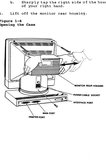
Use Figure 1-4 as reference for opening the case.
1. Turn off the terminal.
2. Disconnect the power cord and data cable(s) from the back of
the terminal; disconnect the keyboard cable from the front of the terminal.
4. Remove the three screws that secure the monitor rear housing to the case (remove the screw under the power cord first, then remove the two screws near the top of the housing).
NOTE: Remove the screws completely. If necessary, tip the
unit bacKwards slightly.
5. To release the clamp holding the bezel and monitor rear
housing together (See Figure 1-4):
a. Grasp the hOllsing with your left hand.
b. Sharply tap the right side of the housing with the heel
of your right hand.
6. Lift off the monitor rear housing.
Figure 1-4
Removing the Power Supply
STOP! The CRT retains high voltages, even after the power has
been turned off, and poses a potential shock hazard. Pollow the
CRT discharge procedure on page 1-4 of this section before removing and replacing'the power supply.
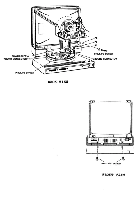
Use Figure 1-5 as reference for removing and replacing the power
supply. .
1. Turn off the terminal and open the case (See page 1-4).
2. With the screen facing away from you, remove the two
Phillips screws that secure the bezel to the case (the
screws are located inside the case, one on each side of the power supply).
3. Disconnect the Ground connector, the power connector (P4)
and the DC connectors (Pl, P2 and/or P3) from the power supply.
NOTE: Only two connectors are attached at Pl, P2 and P3.
Pay close attention to the polarity for reference during reassembly.
4. Turn the unit so the screen faces you and remove the two
Phillips screws (one on each side of the power supply) that secure the power supply to the case.
S. Slide the power supply toward you to remove i t from the
case.
Replacing the Power Supply
1. With the screen facing you, slide the power supply into the
terminal until it locks into the plastic support bracket.
2. Reconnect the Ground connector, the power connector (P4) and
the DC connectors (Pl, P2 and P3)~
NOTE: Any of the three connectors may be used. For
example, you may take the connectors off Pl and P2 and replace them on P2 and P3.
3. Insert and tighten the two Phillips screws that secure the
power supply to the case.
Figure 1-5
Removing the Power Supply
POWER SUPPLY
POWER CONNECTOR
(P4)--::-~~~~~~~:~~~~~~~
BACK VIEW
•
Removing the Video Module
STOP! The CR~ retains high voltages, even after the power has
been turned off, and poses a potential shock hazard. Pollow the
CR~ discharge procedure on page 1-4 of this section before
removing and replacing the video module.
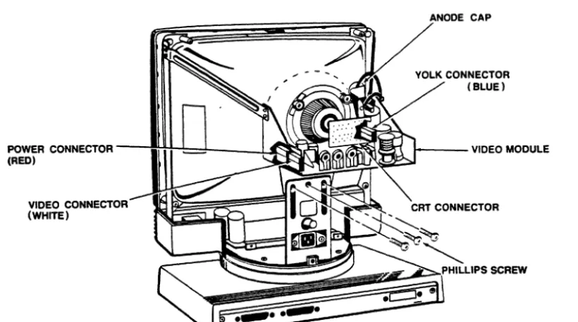
Use Figure 1-6 as reference for removing and replacing the video module.
1. Turn off the terminal and open the case (See page 1-4).
2. Turn the unit so the screen faces away from you.
3. Disconnect the voltage lead at the anode by gently lifting
the rubber cap and unhinging the metal lead. .
4. Carefully remove the CRT connector (small PCB at the back of
the CRT).
5. Remove the power connector (red), the video connector
(white) and the yoke connector (blue) from the video board.
6. Loosen the four Phillips screws (one on each support
bracket) that secure the video module base.
7. Remove the four Phillips screws that hold the video board to
Figure 1-6
Removing the Video Module
POWER CONNECTOR ---lIl+H:d~
__
U~~~L-~;2N(RED)
VIDEO CONNECTOR (WHITE)
Replacing the Video Module
ANODE CAP
1 - - - -VIDEO MODULE
1. Turn the terminal so the screen faces away from you.
2. Slide the video module onto its base (See Figure 1-6) until
the four screw hoI es in the board 1 i ne up wi th the four
screw holes in the base.
3. Insert and tighten the four Phillips screws that hold the
video module to its base.
4. Reconnect the power connector (red), the video connector
(white) and the yoke connector (blue) on the video module.
5. Carefully replace the CRT connector (small PCB at the back
of the CRT).
6. Replace the anode cap:
a. Pull back the rubber portion of the anode cap, exposing
b. Pinch the two leads together and insert them into the
opening for the anode cap in the CRT. Release the
leads.
c. Secure the rubber portion of the anode cap.
7. Tighten the four Phillips screws (one on each support
bracket) that secure the video module base.
8. Replace the bezel and close the case (See page 1-11).
Removing the Logic Board and Shroud
Use Figure 1-7 as reference for removing and replacing the logic board and shroud.
1. Turn off the terminal. Disconnect the power cord and data
cable(s) from the back of the terminal: disconnect the keyboard cable from the front of the terminal.
2. Rotate the complete unit so the back faces you. Remove the
two Phillips screws (in the base) that hold the logic board tray in place.
3. Grasp the logic board tray by its center tab and pull the
tray toward you to remove it. Disconnect the red (Ps) and
white (P2) logic board connectors to slide the tray completely out of the terminal.
4. Remove the four brass screws securing the shroud to the
logic board: remove the six Phillips screws securing the logic board to the tray.
5. Lift the logic board out of the tray.
Replacing the Logic Board and Shroud
1. Al ign the six screw holes in the logic board wi th the screw
holes in the tray.
2. Loosely mount the six Phillips screws that hold the logic
board i~ place:. insert and tighten the four brass screws
that hold the shroud to the logic board, then tighten the six Phillips screws securing the logic board.
3. Replace the logic board tray in the base:
a. Fit the metal flanges on the logic board tray into the
guides at the back of the terminal. Hold the connector
cables up so they do not interfere as you replace the tray.
b. Reattach the red connector (Ps) and the white connector
c. Align the keyboard connector with the opening in the front of the terminal.
4. Insert and tighten the two Phillips screws that hold the
logic board tray in the base.
Pigure 1-7
Removing the Logic Board and Shroud
:;;;;;:
=
=
LOGIC BOARD
~~~~-,,-~
/
LOGIC BOARD TRAY/
· , - - - P H I L L I P S SCREW
Closing the Case
1. Replace the bezel:
a. Place the bezel face down in front of the terminal.
Raise the bezel slightly and hook its two bottom tabs
into the openings (one under the contrast adjustor~ one
under the ON/OFF switch) in the lower case.
b. Swing the bezel up to frame the screen, matching the
c. - Carefully turn the screen away from you while holding
the bezel in place. Insert and tighten the two
Phillips screws (located inside the case, one on each .side of the power supply) that secure the bezel to the
case.
2. Replace the monitor rear housing:
a. Position the monitor rear housing on the case, as shown
in Figure 1-4.
b~ Al ign the screw hole under the power cord wi th the
lower screw hole in the housing.
c. Fi t the four tabs in the hous ing over the edge of the
lower case.
d. Fi t the tab in the top of the bezel into the slot in
the top of the monitor rear housing. Squeeze the bezel
and hous ing together •.
e. Insert and tighten the Phillips screw under the power
cord and the two Phi 11 ips screws near the top of the housing.
Opening the Keyboard case
1. Turn off the terminal.
2. Disconnect the coiled keyboard cable from the front of the
terminal.
3. Turn the keyboard upside down and remove the six Phillips
screws.
4. Turn the keyboard rightside up and remove the top cover.
Removing the Keyboard Circuit
1. Remove the four Phillips screws securing the keyboard
circuit.
2. Li ft the entire as.sembly out of the keyboard case.
VISUAL INSPECTION
A thorough visual inspection often makes the difference between success and failure in a repair attempt. Often a problem can be located just by close visual examination.
Terminal and Keyboard Exterior
Look for signs of accidental damage, abuse, or neglect. Keyboard
Are there any dents or deep scratches on the exterior of the
terminal or keyboard? If so, ask the user how and when the
damage occurred. It may contribute to the problem with the unit.
Terminal and Keyboard Interior
Open the cases and inspect the keyboard and terminal interiors.
Keyboard: Check for signs of spilled liquids, foreign objects,
unplugged devices, defective traces, and signs of overheating and
burning. Check the telephone-style connectors (located on the
back of the keyboard case and on the front of the terminal).
Wiring Harness: Check the condition of the wires and look for
crushed insulation, exposed wires, and loose or broken
connectors. Unplug the connectors and check that the pins are
intact.
Logic Board: Check for loose chips, bent pins on chips,
defective chip sockets, signs of overheating and burning,
defective traces, and poor solder joints. Check that devices are
properly installed.
Power Supply: Check for open fuses, defective components, and
signs of overheating and burning.
Video Module: Check for defective components, signs of
overheating, and defective traces.
Remove all defective modules for closer inspection and repair. When you finish the repairs, replace the module(s) and test them.
FAULT ISOLATION AT THE MODULE LEVEL
TeleVideo's modular terminal design makes isolating a problem to a
particular module easy. You can either follow Table 1-1, Fault
Isolation Guide, or replace each module in turn until the fault is corrected.
To use Table 1-1, find the description that resembles the problem
in the terminal. Then refer to the troubleshooting guide for the
suspected module.
Table 1-1
Fault Isolation Guide
Symptom
No beep on power up
Suspected Module
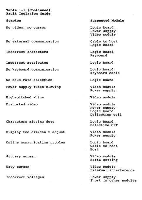
Table 1-1 (Continued). Fault Isolation Guide
Symptom
No video, no cursor
No external communication
Incorrect characters
Incorrect attributes
No keyboard communication
No baud-rate selection
Power supply fuses blowing
High-pitched whine
Distorted video
Characters missing dots
Display too dim/can't adjust
Online communication problem
Jittery screen
Wavy screen
Incorrect voltages
Suspected Module
Logic board Power supply Video module
Cable to host Logic board
Logic board Keyboard
Logic board
Logic board Keyboard cable
Logic board
Video module Power supply
Video module
Video module Power supply Logic board Deflection coil
Logic board. Defective CRT
Video module Power supply
Logic board Cable to host Host
Video module Hertz setting
Video module
·External interference
Power supply
Table 1-1 (Continued) Pault Isolation Guide
Sympto. Suspected Module
No light at cathode filament Video module
Power supply Defective CRT
Display not equal to key entry Logic board
Keyboard cable Cable to bost
Host
.
Visible retrace scanlines Brightness adjustment
Video module Logic board
Keyboard locked up Keyboard and cable
Logic board
Software command
Fails self test Logic board
Keyboard Power supply
Some keys inoperative Keyboard
Logic board
Horizontal bar across screen Logic board
Video module
Poor linearity Video module
Cursor moves, no characters Logic board
Vertical line across screen Logic board
Video module
Crackling sound with distorted video Logic board
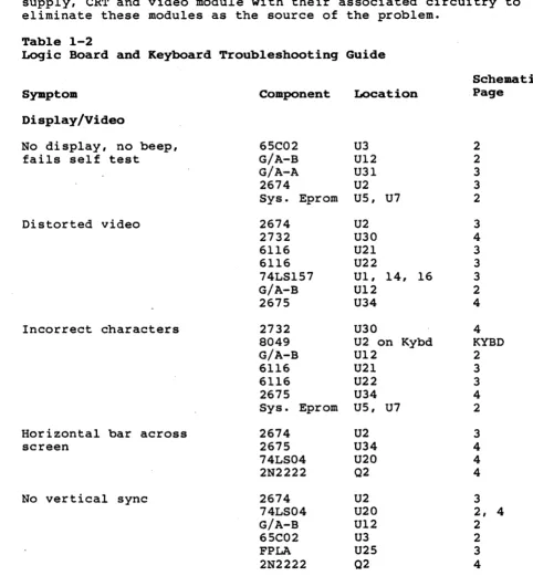
TROUBLESHOOTING THE LOGIC BOARD AND KEYBOARD
This section is a guide to component-level repair of the logic
board and keyboard modules. Find the symptoms in Table 1-2 that
resemble the problems in the terminal you are repairing. Then
locate the suspected defective components. If you are not sure
that a component is satisfactory, replace i t before proceeding to
the next test point. Before replacing a chip or component, check
its inputs and outputs for proper levels and signal quality_
NOTE: Before referring to Table 1-2, test and/or swap the power
supply, CRT and video module with their associated circuitry to eliminate these modules as the source of the problem.
Table 1-2
Logic Board and Keyboard Troubleshooting Guide
Sy.ptom
Display/Video
No display, no beep, fails self test
Distorted video
Incorrect characters
Horizontal bar across screen
No vertical sync
Component
6SC02 G/A-B G/A-A 2674
Sys. Eprom
2674 2732 6116 6116 74LS1S7 G/A-B 267S 2732 8049 G/A-B 6116 6116 267S
Sys. Eprom
2674 267S 74LS04 2N2222 2674 74LS04 G/A-B 6SC02 FPLA 2N2222 Location U3 U12 U31 U2 US, U7
U2 U30 U21 U22
U1, 14, 16 U12
U34
U30
U2 on Kybd U12
U21 U22 U34 US, U7
U2 U34 U20 02 U2 U20 U12 U3 U2S 02 Schematic Page 2 2 3 3 2 3 4 3 3 3 2 4 4 KYBD 2 3 3 4 2 3 4 4 4 3
2, 4
2
2
3
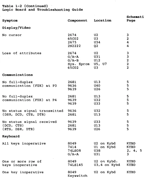
Table 1-2 (Continued)
Logic Board and Troubleshooting Guide
Symptom
Display/Video
No cursor
Loss of attributes
Communications
No full-duplex
communication (FDX) at P3
No full-duplex
communication (FDX) at P4
No status signal transmitted (DSR, DCD, CTS, DTR)
No status signal received (DCD, CTS)
(RTS, DSR, DTR)
Keyboard
All keys inoperative
One or more row of keys inoperative One key inoperative
Component 2674 65C02 2675 2N2222 2674 G/A-A G/A-B
Sys. Eprom 65C02 2681 9636 9639 2681 9639 9639 9636 2681 9639 2681 9639 8049 7414 74LS08 G/A-A 8049 74LSl45 8049 Keyswitch Location U2 U3 U34 02 U2 U31 U12 US, U7 U3 U13 U40 U26 U13 U32 U33 U32 U13 U33 U13 U26
U2 on Kybd Ul on Kybd U38
U31
U2 on Kybd. U3,4 on Kybd U2 on Kybd
Schematic Page 3 2 4 4 3 3 2 2 2 S 5 5 S S S S S S S S KYBD KYBD
2, 4, 5 3
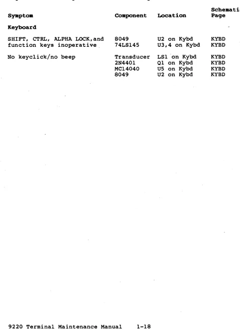
Table 1-2 (Continued) .
Logic Board and Keyboard Troubleshooting Guide
Sympto.
Keyboard
SHIFT, CTRL, ALPHA LOCK, and function keys inoperative.
No keyclick/no beep
8049 74LSl4S
Transducer 2N440l MC14040 8049
Location
U2 on Kybd U3,4 on Kybd
LS1 'on Kybd 01 on Kybd US on Kybd U2 on Kybd
Scheaatic Page
KYBD KYBD
TROUBLESHOOTING THE VIDEO MODULE
STOP 1 HIGH VOLTAGES ARE PRESENT ON THE VIDEO MODULE.
USE EXTREME CARE DURING TROUBLESHOOTING.
Visual Inspection
Turn the terminal off and remove the monitor rear housing, as described in Section 1 of this manual (Removing the Modules). Check the following possible problem areas before removing the video module from the terminal.
a. Connectors: check for loose or damaged connectors,
dirty contacts or bad crimps.
b. Wires: check for any broken, loose or frayed wires.
c. Components: check for any deformed, leaking or
discolored components.
Correct any defects, then retest the terminal before continuing.
Remove the video module from the terminal, as described on page
1-8. Inspect the video module for:
a. Deformed, leaking, or discolored components.
b. Damaged components.
c. Cracked or lifted traces.
d. Poor solder joints (loose solder lumps, solder oridges,
or cold solder joints).
Adjustments
Four adjustments can be made to the video module: height,
linearity, brightness and focus. The controls for height,
linearity and brightness are labeled on the back of the video module; the control for focus (VR2) is on the front of the video
module. Use the following chart to determine the proper control
to adjust.
Symptom
Character intensity too bright or too dim
Whole screen is too taIlor too short
Characters are not even in height from the top to the bottom of the screen
Charact.ers are not in focus
Control
Brightness
Height
Linearity
This section is a guide to component-level repair of the video
module. When in doubt regarding the proper operation of·a
component, replace i t before proceeding to the next test point. Before replacing a chip or component, check its inputs and
outputs for proper levels and signal quality.
Symptom: No vertical deflection
1. Check IC-l for vertical sync at IC1, pin 8.
2. If the signal is improper or missing, trace back to P10 for
vertical sync at pin S.
3. If the signal is good, trace forward to IC-l (pin 4) for
. deflection drive, and related components up to the vertical
·yoke. .
Symptom: No horizontal deflection
1. Check the base of 0301 or the cathode of D301 for horizontal
sync.
2. If the signal is improper or missing, trace back to P10 for
horizontal,sync at pin 1.
3. If the signal is good, check the output of the horizontal
drive transformer T30l and the base of 0302. Trace for the
presence of horizontal deflection through 0302, C306, L30l, and L302 up to the horizontal yoke.
Symptom: Audible high-pitched whine
SCHEMATICS
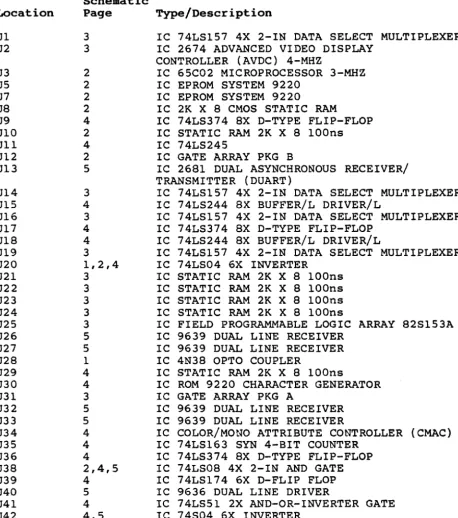
Table 2-1 gives a brief description of the chip at each location on the logic board. Refer to Table 3-1 for the part number of components at each location.
Table 2-1
IC Reference by Board Location
Location Ul U2 U3 US U7 U8 U9 UIO Ull U12 U13 U14 Ul5 U16 U17 U18 U19 U20 U21 U22 U23 U24 U25 U26 U27 U28 U29 U30 U31 U32 U33 U34 U35 U36 U38 U39 U40 U41 U42 Schematic Page 3 3 2 2 2 2 4 2 4 2 5 3 4 3 4 4 3 1,2,4 3 3 3 3 3 5 5 1 4 4 3 5 5 4 4 4 2,4,5 4 5 4 4,5 Type/Description
IC 74LS157 4X 2-IN DATA SELECT MULTIPLEXER IC 2674 ADVANCED VIDEO DISPLAY
CONTROLLER (AVDC) 4-MHZ
IC 65C02 MICROPROCESSOR 3-MHZ IC EPROM SYSTEM 9220
IC EPROM SYSTEM 9220
IC 2K X 8 CMOS STATIC RAM
IC 74LS374 8X D-TYPE FLIP-FLOP IC STATIC RAM 2K X 8 lOOns IC 74LS245
IC GATE ARRAY PKG B
IC 2681 DUAL ASYNCHRONOUS RECEIVER/ TRANSMITTER (DUART)
IC 74LS157 4X 2-IN DATA SELECT MULTIPLEXER IC 74LS244 8X BUFFER/L DRIVER/L
IC 74LS157 4X 2-IN DATA SELECT MULTIPLEXER IC 74LS374 8X D-TYPE FLIP-FLOP
IC 74LS244 8X BUFFER/L DRIVER/L
IC 74LS157 4X 2-IN DATA SELECT MULTIPLEXER IC 74LS04 6X INVERTER
IC STATIC RAM 2K X 8 lOOns IC STATIC RAM 2K X 8 lOOns IC STATIC RAM 2K X 8 lOOns IC STATIC RAM 2K X 8 lOOns
IC FIELD PROGRAMMABLE LOGIC ARRAY 82S153A IC 9639 DUAL LINE RECEIVER
IC 9639 DUAL LINE RECEIVER IC 4N38 OPTO COUPLER
IC STATIC RAM 2K X 8 lOOns
IC ROM 9220 CHARACTER GENERATOR IC GATE ARRAY PKG A
IC 9639 DUAL LINE RECEIVER IC 9639 DUAL LINE RECEIVER
IC COLOR/MONO ATTRIBUTE CONTROLLER (CMAC) IC 74LS163 SYN 4-BIT COUNTER
IC 74LS374 8X D-TYPE FLIP-FLOP IC 74LS08 4X 2-IN AND GATE IC 74LS174 6X D-FLIP FLOP IC 9636 DUAL LINE DRIVER
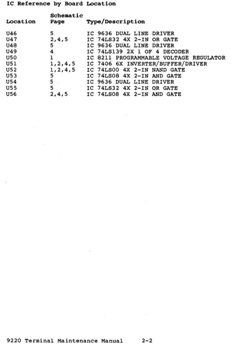
Table 2-1 (Continued)
IC Reference by Board Location
Scheaatic
Location Page Type/Description
U46 5 IC 9636 DUAL LINE DRIVER
U47 2,4,5 IC 74LS32 4X 2-IN OR GATE
U48 5 IC 9636 DUAL LINE DRIVER
U49 4 IC 74LS139 2X 1 OF 4 DECODER
U50 1 IC 8211 PROGRAMMABLE VOLTAGE REGULATOR
U51 1,2,4,5 IC 7406 6X INVERTER/BUFFER/DRIVER
U52 1,2,4,5 IC 74LSOO 4X 2-IN NAND GATE
U53 5 IC 74LS08 4X 2-IN AND GATE
U54 5 . IC 9636 DUAL LINE DRIVER
U55 5 IC 74LS32 4X 2-IN OR GATE
D
c
8
A
c:.UAAIiNT lOOP
... t-...
--ift ..
+llV L_-<i _ _ --'_
~'S __ ~R~'D~'"~ ____________ O-________ ~ ____ ,
1
•
pH c:::=>
1
P4 - 7 c:::=>---l-+
PI-6
1
,5.
R"
... n;
D
'5. .~.
.5
2NUII
CR'
IHI)14
4
toB IN'14
3
P9-S
P9-2
l.r ---jC>-P'-Q
r;
L---c:::=> P9-' PI)·7
It..:o-P9-l
I
tI'.
+---Ic:::=> PH
".
1_ .. ---1---ic:::=> II p, ...
".
1·"
c:::=> PI.'~'""2'---'R"-'S[=' __ SHT S
>co-!!-~ ... ----,p--..__+---'R"-""'[,,'-- SHU.3
PII-I
2
PIt£L rEL
A PROD "'E.L
to :. ... '110"11502 ... ur?
~IS~l , ..
3Z3tT nt/,"
NOTE: Ul.U.aS orNEIbVIS. S~IFJ!P.
,. ALL l'iSJ.50T~ ..,eoE 'VAUJI!D 1 .... OH .. 5t t!J1. AUD ARE. 1,14 ~TT.
D
c
8
~-5c::>~---I---~~
( , . :".64.65
..
, Plt·jlll 31 3.1 2;2. ALL CAPACITO~ Ae'E \lALu£D , ....
MICeoFARADS 110'/. AUK) AilE ~ Voc •
PS-'
n-s L.-.::>---'
P5-l
P7-1
P7·2
PII· 28.30, Jl,14,l' •
•
p,
-7.---ir
~
- - :& •• -! . ____ -..
~=-. ~~A
l It ....o
c
II
RPi-l
o\.lK
{ PHT", DtA
VIT' 'UDL
•
7 6
" ", ,',. III
"DD PIiio'4. III
I vpp Ub
1---Ul 2.7128
7 6
5 4
.DD P.... Ill:
I 'IIpp U4
1---5 4
~61
fClO'{l
UB3
C"""·07 CRI","
!iHT ],I"I~
CR' 1
.~v
!
c:.16 IN914~ "~lIp'
1
INC)".~.
CR,.
JI"JC((
,
..
~'.':1
<R..
1"141 I" gl4( ' " 0-, ~
'1Y. 'K U _B TI
0' "1/1
1
lko42,L4lo M,...
-t'2vf <I't....
AtZ. -"12
~MT ~
... ,/ ~':l"lf)
iLl\.
P" . . . }
... 1 ~IS, •
....
Pt'wll!iC«EEA C_At'4 ""T ,.
PHIC 0 pu-.
,.. T ,-~"'TC,",
SMT ~
_,:; :- e.li:IoMdoo~"""
• _ - ! - ' - - L _ PC B '>CH(MAT Ie ----I 1_--:-:::-_-- - . -~ -I CONTROL BOARD 9220
;:--~~, ,-- .: ,--__ --_____ ~wD~lc •• ~d···tI32273-00~mN~
==~-:
=-..:=
e3 2
0
c
8 I 7 I 8
I
.,.n __ ·t""~!· _ _ _ _ _ _ _ _ _ _ _ _ _ --,
T
••
'I" ,,~ .... He
,.
,CUR'OOFI.
..
U2 iM1R '9
'l,,14- H~"f"C
"
A'IOC IiU ... tU' ..
'"
A0
A.
~ A'
..
DII.O'D/I
"
o""o0 I ,~
0",,002
-",
0"'(0)1 ,,"
OA004'''''' Z9 Poll..OO51l.'" -..e
~OD6JUi ~,
O,...,OllL"'!'. ~ D.'D08/f1,. g CMDD9/DW ~'HIL J--N/C.
~T" Dl'OIHIl UL
.. -n
--
fIHT.t,. R/Vf~I(T£~ 'I' ~ -= ..
"It .. I
~ 11
"
iiiHc. ~ , ~
It "'4 sarl5 6. m:K
,
B 8Z51~~A U25 •..
"NT 2: FP,-"
Mit '9
..
.,. ...~~~' ~ 9
''!ll'll'
...
,.
COff' ~~NC.•
I ., II 5 I 4 I
,
,,' .. '{we
~I-IT'"
C.uA.";:oOR ,>IT ..
NM ;111 t H'&"NC.
BLANK) S,-...T 4
OAOO't ow
~..
D Ie. UI~T
10 It '4L.~11!o1 11&
13 Vu.
Zll) ~
58A 'f"~
II:~ ~~~
14 .OE &MD~l~D~
"I
at
'I
•• v
••• z. :za
I
,
".wa:l va.
q
,fit, en., U22
. "-t ""1 4116,
.4 "'!Iob40 , "
q
~ 01 11...
02 r!oI~
.,
0", 151••
P4 ,.I~ •• O~ 1'1
All' l~
...
..
,"
~. c 2~ RJWI'"I 07 19
~
.
2 -"llt Colilt» ~ Ali ~• Z'l'~~
APl-~ I~ -=
I I
3 I I
III~
/ ~ ./ ~ ~ 7 "'(.~C.D •
~CDI
I~C02 k '----:!-CO~ U31 ~ z C04
!t C05
l~c""
~tD7
L _ _ _ _ '~~ KiiDR5
L _ _ _ _ _ ~z.· MUv. su
61A
'K
L _ _ _ _ _ _ -""'~ ~
.. ____ N_'t_~_2gjl! ~MNI4.Ii11 K60/JAQ. I~
. -_ _ _ _ _ ~., 111.80 bD KeO/OvfL 1&
~ _ _ _ _ ..!;'.:J3 CCLK
. . _ _ _ ~8 .~ Rud . - - - - " ' , . " OR CLK
!'H't Z (nQ':-CDJ'
~ swTI
l -_ _ _ _ _ _ _ _ _ _ _ _ _ ~---~C~CL~~L &~T4
11.60 iU.D
::...
- - -.=.
-. -. -!--- :-. L· - PCB SCHEMATIC
~ •• ~ . ""1- 'CONTROL BOARD 9220
:=::...
k~~-+---·-~.:...=-::.__J.--...·-_\'D-ri;D.T.'NT
~ IJ227J.00J:t.-.. • $ColU SHUT Of
I
D
-c
-B
--
!lM15 nAt.OIOIULcuRSOR.
PU-t,
~5V
-A D2-D7
I 5IhT 2 ~ CONTROL REG I
u-""
C.MA':
~b7rl
"',,-):
.---~Ar--4' •• ~
4.,. .... ~ ,.t.;[li:
rt---4---~~:4~ :~~~:l
...
Ff4-~
51 '4'(.
'"
•.
., .... " I-.f't..,",,"""".
.0 "k'.\Ihl'.v:
00'..
M\'IIDv:
AI"..
'"L
V':A£i4- ,. "'HILT
I'
~T fa. .!':.~'!C/",iI;;J!!!... __________________________________________________ --,~~~~ .1 10
'
I ~T.{.!H~'~V~"t~ ____________________________________________ ~~; U'8Jr:;L·_~_a_' ____________ -t __ U_l_S ___ L_>_~_4 ________________ ~
_(OI'lP!.YNC ~
I V
...
I
'~ \I~e ' ~1 .•l C1
T"
.hWJ
1" ".1
.''V>/'v--::- 47":'-1I2W
()~N~"'I(
LUI". ~ Nit
...
-
.-I
) "II ~·tI
R,
<1~
.
....
-
--~n
nl:-....
....,
.~"
--
~ " .L.0 RI> Z~ Ole I .
---
L·~~ I---';-'" I
C'\iQl
IH~14
..
~-I·~··
.,y
01l:kMdeo Systems, Inc.
,)1 ..
I~~i-···
" . . .-
..
001:_ ...-
....~, ...
.. -.c.D __ , , , , _
... u .. • ... _ _ "",
.-1 "
--PCB SCHEMATIC CONTROL BOARD 9220 '
l---______ -l. __ ~~ __
!:"' .. :,. ...
r_'ti-..----_f·'&io ... r
t
132213-00r;:
D
c
B
A I
pl-6 r - ' ) O~A
f- ... <,I"
nt;Th
~
"'T Z OT.
"" l
~BDIRO
IU .. Ct
n .
-12.V
\I'
• •
'--14S Uf.!.\.:-_ -12:..,
41 ./ "12.'"
.-_ _ _ .... ____ -B. RY!oTAll opGf-#-- .... c
1 Co< ::t: yz DPzt-l!-H.C ,
rl-
n
='T' "OPI [=:J 36864 2
f'NTR r..rR
'"0
1;)"'/bO
-L L.. . 3J RrSTAL 2 ~~I-,-'-,--...J c ••
r .
L - ,1
Cb~SHY 1 KaD Ollfl J1 (Po. IP5f',,,-8---t-tt--' '
"''' -'".'."---..,.l'---!-jl AIjJ UI,!.
ITRNf"o:.'--,-.v-H-+--+' i»o-tL.-=---"="-lSHT ~
,.if
Z~T Z {
",T •
P6-4
:;'HT
2-1'6-' ~"fT4 1'6-6 PJ-8 [J~", OT. OUART 00_01
i:~==~~:;
%",:"V"b-J-
la
I2 ;:'0
'---,:"--tA~. OP4~ .... c ! u:.t." ~~ ~ ~Zl ~'\I"
--"'=!---"'''f DP7 ,. 75K lll'P( Tl-'_.~ _ _ _ _ _ _ _ _
---..,l'-___
...12~5~10
~.IArd h
C=>.5V
--
.'----"''',01
~~!I_'»<L.--+t-t--f_l-""_l-+/_---"'LU_S~._1': r:~7t
C84:i~:::::::::::::::::::::~;~;~~ ,,~~ ~ u~ .::5><4>--t'7_+-'--' .. ,._J _ _ t-_____ ....
f
~='___t "0R ••
4.1K
IfO
tlII
R£'5ET
Zl IXD "
I
I V ! C,.18 OS RXO 31 U~~!> 9636 ~
22 Db {OSA)IP0f--:!,7--._f-' ' - t - - - -2'L ) ~>:>f'.-... --+---'"!L.j
, • • 7 IP:> J6 + R~~~~)
ji
'2V5
t12" , R I czS9 UN -~ NL ~ cal _ 1SK f - : ~
8 TN ,-- 2 11""1 S f, Tci~
J4 Isn bNO L--...! ~~ 1 . 1Mot
.IS
""0>
[lATA 10 PRltH[R
~~8
7m :'..
I~ !~!L~~~~~~
________
t:~2~U~5~3~.3==~ L=====~===========~~_r---'t_t_--~,~~tb~---~~'-~-~--+---Ill'-1
4 14L!o3Z 1 4 :!: ;~p,
no
9
RXDHQOC>----::L
='!!L---""'-L }U41
O"'l,~v
~
1 u~2
RlSO 044 10K 1--4'" PJ-20 Pl-II :;HT J P3~2 pl-4 P!l·Z~
p"q -3
PJ-S U, L-______________________________________________ -LTX~OI._'____ ~, 2
RXDI
"iI Z
P)-) AXD ,.,
f-4-2 .'0
~RS'
~
..
~PI_4 -12'"
A
U;, [(,£2 _ _ _ _ _ _ _ _ _ - '~U~
~l(D IN
SI"lT I
I
{"'.b-"'V
FOR S636A PIN 5,,, -12\) PIN 4:= bNlJ
D I -c
--B f--I----=_=._~--~~=_= .. =_.=.~m. .. ~~----.---~---~_;A
•. 1eltMdoo liystems,lnc,
I~:J~~
.-
"-
;T~~Iii-~ ... --t-.,CONTROL BOARD 9220 ""D'
c
B
A
o
C60i
OJU
~JOI
47 V,HEI6ftJ
LINEQ.lfV
NO"i-D. UWl.IUt.1!> OTHERWIU-.p&'~FIIU:> TO
CRT HEAtER
1
DJOt 1N4148
L M-I.. R!L1!>t'iiiTO_ ARt!. I/+W. 1:5%. f.IIiSoI",.ANC. .. It. .... 01< ... 1>,
2. DS01. DSOio (IlNNEC.TfO IN SERIE~.
•
7 8V.lINEARITY
D~
"'R8!'a6
6
A 'fifOO REt 8 IWPf\Q'IE ",OEO
lJPDA '110f 0 ftOD HOt( ..
(Jo'
.
I
2:'~~.F (lOS ZSV/Z/IlU
,t.
I
I
I
I 0504
BAIS.
I
I
CSOlKXJ\/
IDOl
...
..
--_
_ ... ooe _ _ ....-.
E==¥.i=e
"
- - - =:t=
D
B
A I
B 7 6
...
4 UI
14,. 1414
1----j~,.._;~;I_-_.il .. JI 6 'J UI 8 iHi
1 ''''4
7414-;:-+--.-411--.;1 +12V VAl +~"
1-_-l>-F.';c.;;;':'l--+-I..,..._;~f7a
MO~
2 .t"
40 __ ,c;.I I
I I
GNO .1
ii=h : :
l
7 :JIrnT , 8. _
'
-'i~:v
9
f~f';¥';¥;·lu
voo
-=-
I
+t
Y0'
' i i
I
l.lKOZ ,
..
3..lK JOt,
NORM A
lL1
IN
T
CAl AI• ~uu
U" ·I~4
1'2
I~V~Yn UZ
804'1
eNg 'I~ SO
'I' 2t '"
.
• OO 1
5 4
~--~--~r---4---?I' pL---r~~~-r-+---~---~XI
~--+-'->--'-+---+----~.xz
pL--~~~~-+-4---~---+x'
~-~-r-~>-r-+----+----~X'
~---r-+-=~-r-+---4---~X'
~-~---4---~X1
1!L---¥lI' (;1.1' .~~"
WC140"0
'---t========:;;::==========~I{,vc;c;
& 5~~~~:~~ IN OA5H£D LINES ARE CUSTOW£R
".RU PCB PIN
l.OLL DIOOES ARE INg'4.
a.ALL CAPACIlOR "''''LUES ARC: IN MICROFAAIo·D5 '1O'l
AHO AA£ ~O voe MIN.
' .... lL R[SISTOR VALUU AAE III OHIo4$ t ,,. AHD
4 U O I O , R , , " J \ r -_ _ '..J;r ~
TRAN50UC£R~ ~4401 i,U -=
t IZY -::
D
T
..
Il") Ul·
"'" .. I
..
74lS'4$ :.
.
..
·
-L
I • ,. .
.
.
-::- I Z l
•
~•
VID til 1'2 YI' YI4 'IS
c
~! 7 6 4 3 2
~
m=ISE~
~I/T II-0 D
'0 YO yz n YO n n V7 VI YO "Q VII "2 VIJ .14 YOS
c c
B E
.,~---4----__ ~ ______ ~ ____ -4 ______ ~ ______ ~ ____ -+ ______ +-____ ~~ ____ ~ ______ ~ ____________ ~ ______ ~ ____ ~
'W.Tat ORIENTAllON
A
~
fAI
-~
---.
.
-..
:-
_.+--~"":".:".=
ORDERING SPARE PARTS
~ou can order spare parts by telephone*, telex or by written
purchase order. To place an order, contact the TeleVideo
Regional Sales Office in your area, or contact our Corporate Spare Parts Order Entry Department at the following address:
TeleVideo Systems, Inc. 1170 Morse Avenue
P.O. Box 3568
Sunnyvale, CA 94088-3568
Sunnyvale: Telex: Fax:
TWX
or call
408-745-7760 474-5041 TVISYS 408-734-1927 910-338-7633
All orders are shipped F.O.B. our designated site.
TERMINALS SPARE PARTS PRICE LIST
For spare part prices, refer to the Terminals Spare Parts Price List in Section 7 (Addenda) of this manual.
Table 3-1
9220 Parts List
PCB ASSEMBLY LOGIC BOARD - PART NUMBER 132270-00
Part Number Description Location
Integrated Circuits
120274-00 IC 74LS157 4X 2-IN DATA SEL/MLT U1, 14, 16, 19
130234-00 IC 2674 AVDC 4-MHZ U2
130236-00 IC 65C02 MICROPROCESSOR 3-MHZ U3
180002-82 IC EPROM SYS 9220 COOO U5
180002-81 IC EPROM SYS 9220 4000 U7
121387-00 IC 2K X8 CMOS STATIC RAM U8
120290-00 IC 74LS374 8X D-TYPE FF U9, 17, 36
131615-00 IC STAT RAM 2K X 8 lOOns U10, 21-24, 29
120362-00 IC 74LS245, N8T245N U11
130180-00 IC GATE ARRAY PKG B U12
130222-00 IC 2681 DUAL UART U13
120442-00 IC 74LS244 8X BFR!L DRVR/L RCV U15, 18
120248-00 IC 74LS04 6X INVTR U20
130920-00 IC FPLA 82S153A U25
131636-00 IC 9639 DUAL LINE RECEIVER U26, 27, 32, 33
120350-00 IC 4N38 OPTO CPLR U28, 45
180002-90 IC ROM 9220 CHAR GEN U30
130170-00 IC GATE ARRAY PKG A U31
130238-00 IC COLOR/MONO AT CONT (CMAC) U34
120276-00 IC 74LS163 SYN 4-BIT CNTR U35
120252-00 IC 74LS08 4X 2-IN AND GATE U38, 53, 56
120282-00 IC 74LS174 6X D-FLIP FLOP U39
131635-00 IC 9636 DUAL LINE DRIVER U40, 46, 48, 54
120262-00 IC 74LS51 2X AND-OR-INVTR GATE U41
120246-00 IC 74S04 6X INVTR U42
120258-00 IC 74LS32 4X 2-IN OR GATE U47, 55
120272-00 IC 74LS139 2X 1 OF 4 DECODER U49
131614-00 IC 8211 PROG VOLT REG U50
120348-00 IC 7406 6X INVTR BFR/DRVR U51
120242-00 IC 74LSOO 4X 2-IN NAND GATE U52
Resistors and Pots
120521-00 RES CF 1000 OHM 1!4W 5% R1, 3, 10, 28,
49, 52, 65
120519-00 RES CF 510 OHM 1!4W 5% R2,40
120375-00 RES CF 560 OHM 1!4W 5% R4
120531-00 RES CF 4700 OHM 1!4W 5% R5, 21, 22, 33,
.36, 39, 43, 47, 60, 61, 63, 64
120515-00 RES CF 330 OHM 1/4W 5% R6
120317-00 RES CF 750 OHM 1/4W 5% R7
120517-00 RES CF 470 OHM 1!4W 5% R8, 27
120523-00 RES CF 1800 OHM 1!4W 5% R9
120339-00 RES CF 150 OHM 1/4W 5% Rl1
Table 3-1 (Continued) - 9220 Parts List
PCB ASSEMBLY LOGIC BOARD - PART NUMBER 132270-00
Part Number
126183-00 126184-00 126182-00 130192-00 270702-00 120337-00 130194-00 120341-00 120527-00 121440-00 120391-00 120511-00 120323-00 123482-00 120325-00 120363-00 120413-00 120427-00 Capacitors 130172-00 130174-00 130176-00· 122614-00 130196-00 130177-00 130179-00 130171-00 130173-00 130175-00 130202-00 130183-00 Miscellaneous 120475-00 122070-00 131551-00 120469-00 120459-00 120455-00 Description
RES MF 68K OHM 1/4W +/-1% RES MF 1M OHM 1/4W +/-1% RES MF 22K OHM 1/4W +1-1%
RES WW 37.40 OHH 1/2W 1% RES MF 47.5 OHM 1/2W 1% RES CF 4iK OHt1 1/4W 5% RES CF 22 OHM 1/2W 5% RES CF 10K OHM 1/4W 5% RES CF 3300 OHM 1/4W 5% RES CF 82 OHM 1/4W 5% RES CF G.8K OHM 1/4W 5% RES CF 68 OHM 1/4W 5% RES CF SlK OHM 1/4W 5% RES CF 15K OHM 1/4W 5% RES CF 75K OHM 1/4W 5% RES CF 22K OHM 1/4W 5% RES PK 4.7K OHM 10 PIN SIP RES PK 1K OHM 8 PIN SIP
CAP GL PK .1uF 2SV +80%
CAP GL PK .01uF 25V +80% -20%
CAP ELECT 10uF 16V +80% CAP ELEC 1uF 10V
CAP MONO 22pF 50V +/-10% CAP TANT 4.7uF 16V +/-20% CAP GL PK 47pF SOV
CAP GL PK 10pF 2SV +/-20% CAP GL PK 330pF 25V +/-20% CAP ELECT 22uF 16V +80% CAP GL PK 150pF 50V +/-10% CAP GL PK lOOpF 50V +/-10%
DIODE 1N914
DIODE ZENER 3.6V TRAN 2N4264 NPN
TRAN 2N2222A NPN/SILICON TRAN 2N2907A PNP/SILICON TRAN 2N4401/2SC1166 NPN/SIL
Location R13 R14 R15 Rl6 Rl7 R20 R23
R24, 46, 48 R25, 34 R26 R29
R30, 31, 35 R37
R38
R44, 53, 54, 62 R50, 51
RP1, 4
RP3
Cl, 3, 7
C30, 31, 37-39, 41-44, 49-52, 54-59, 61-69, 71-74, 80, 82-88
C2, 70 C5 C6
C8, 33, 45 C9, 15 C14
C23-27, 76
C28, 32, 35, 36 C77
Cal
CRl, 3, 4-11, 14
Table 3-1 (Continued) - 9220 Parts List
PCB ASSEMBLY LOGIC BOARD - PART HUMBER 132270-00
Part Number Description Location
121262-00 VOLT REG 79LOsAC VR1
131386-00 BATTERY LITHIUM CYLINDER B1
270667-00 CRY 17.2414-MHZ Y1
122168-00 CRY 3. 6864-MHZ Y2
270721-00 CRY 24.8618 MHZ CLOCK OSC U37
122084-00 CONN 6P MOD JACK RJ12 RT-ANG PI
120988-02 CONN 4P HDR WT (sP W/i2P OUT) P2
121653-01 CONN 25P D-SUB FEM THRD P3, 4
122639-00 CONN 4P HDR RED (SP W/i2P OUT) P5
120988-00 CONN 2P STR WAF P10
120984-02 SOCKET 40P IC DIP U2, 3, 12, 13,
31, 34
120984-04 SOCKET 28P IC DIP US, 7, 22, 23,
30
120984-01 SOCKET 24P IC DIP U8, 10, 21, 24,
29
120984-06 SOCKET 20P IC DIP U25
Table 3-1 (Continued) - 9220 Parts List
PCB ASSEMBLY VIDEO MONITOR - PART NUMBER 247726-00
Part Number
270884-00 270883-00 120485-00 241301-00 241300-00 270882-00 122022-00 120441-00 121801-00 242817-00 130746-00 130134-00 130838-00 242000-00 120377-00 121768-00 120403-00 120531-00 131582-00 240102-00 240103-00 120337-00 240104-00 240108-00 131502-00 249700-01 240105-00 240106-00 240107-00 121967-00 249017-00 241124-00 130127-00 122800-00 240907-00 130827-00 130186-00 270880-00 130126-00 240908-00 249015-00 249003-00 121959-00 121962-00 249027-00 240700-00 Description
TRAN KTC2235(O) TRAN BU406
DIODE IN4148 SWITCH DIODE MR856
DIODE BA159 DIODE lN4755 DIODE 1N4004 MOT
POT TRIM lOOK OID1 TOP-ADJ PCMT POT FOCUS 2M OHM
TRANS H DRIVE HOT TRANSFORMER FLYBACK COIL LINEARITY 52-MHZ COIL WIDTH lOuH +40%
IC VERT AMP TDA-1170N RES CF 47 OHM 1/4W +/- 5% RES CF 10K OHM 1/2W 5% RES CF 220 OHM 1/4W
RES CF 4700
omi
1/4W 5%RES CF 200K OHM 1/4W RES CF 180K OHM 1/4W RES CF 390K OHM 1/4W RES CF 47K OHM l/4W 5% RES CF 220K OHM 1/4W RES MF 1.0 OHM lW
RES CF 68KOHM 1/4W 5%
RES CF 33K OHM 1/4W RES CF S6K OHM 1/4W RES CF 3.3K OHM 1/4W RES CF 3.3 OHM 1/2W CAP ELEC 4.7uF 16V CAP PF O.OluF 50V
CAP POLYPRO 0.033uF 630V CAP ELEC 220uF 25V
CAP ELEC 16uF 2SV (NON-P) CAP PF 0.1uF SOV
CAP ELEC 100uF 100 RADIAL LOS CAP CER .02uF 50V
CAP MF .01uF 800V 10% RAD CAP MYL .033uF 400V
CAP PF 0.1SuF 50V
CAP ELEC 2200uF 16V 16X2SMM CAP ELECT 100uF 25V 8X11.SMM CAP CER 220pF 50V
CAP ELEC 2200uF 10V
CAP ELECT 47uF 25V 6.3X1IMM CAP CER 470pF 50V
Location
Q301 Q302 D301
D302, 303 0502-504, 506 0505
0601
SFR1, 2, 4 VR2 T301 T302 ('301 L302 ICl
R30l, 501 RS04
RS12
R601, 611 R602 R603 R604 R60S R606 R607 R608 R609 R610 R613 R614 C301 C302 C304 C30S C306
C307, 601, 603, 604, 611
Table 3-1 (Continued)- 9220 Parts List
PCB ASSEMBLY VIDEO MONITOR - PART NUMBER 247726-00
Part Number
122174-01 122173-01 122172-01 123059-01 132329-00 131862-00 249078-00 121078-00 123107-00
Description
CONN 4P HDR W/LOCK WHITE CONN 4P HDR W/LOCK BLUE CONN 4P HDR W/LOCK RED
SCREW M3X8MM SELF TAP PH PHL CVR SHIELD FBT
PCB ASY SOCKET 9220 SCREW M3X6 BH
WASHER M3 FLAT ST ZN
WASHER M3 STAR EXT LOCK ST ZN
PCB ASSEMBLY POWER SUPPLY - PART NUMBER 132324-00
Table 3-1 (Continued) - 9220 Parts List ADDITIONAL PARTS
Part Number Keyboard 130932-00 130936-00 130935-00 130175-00 130178-00 120265-00 120245-00 120986-01 122450-00 121700-00 121390-00 120354-00 120373-00 120319-00 120527-00 270846-00 122151-00 120455-00 120475-00 121261-00 131159-00 131158-00 131157-00 122161-00 122084-00 .121063-10 121074-00 121752-03 case 131853-00 131747-00 122187-00 132337-00 132165-00 132166-00 132155-00 132148-00 132147-00 132146-00 121076-07 121074-00 121074-09 121074-02 121074-03 123059-00 Description
KEYBOARD ASSEMBLY HSG KYBD BOTTOM HSG KYBD TOP
CAP ELEC'l' 22uF 16V +80%
C~P CER .01uF 50V +/- 10% CAP ELEC 2.2uF 25V 10% CAP MICA 20pF 50V 2% CRYSTAL 5.7143 !-1Hz
IC 14040B 12-BIT BINARY COUNTR IC 74LS145 BCD TO DECI DECODER IC 8049 MICROCOMPUTER
IC 7414 6X SCHMITT TRIG RES CF 27K OHM 1/4W 5% RES CF 1200 OHM 1/4W 5% RES CF 3300 OHM 1/4W 5% RES PK 6.8K OHM lOP SIP TRANSDUCER AUDIO
TRAN 2N4401/2SC1166 NPN/SIL DIODE 1N914
VOLT REG 78 M05
KEYSWITCH NONLOCKING MAR KEYSWITCH NONLOCKING KEYSWITCH LOCKING
CBL ASY 6 CONDUCTOR RJ12 CONN 6P MOD JACK R.J12 RT-ANG SCREW 6-32x 1/4" PH PHL ST ZN SCREW M3 X 6f.1M PH PHL ST ZN NUT 6-32 HEX ST ZN
CASE ~SSEMBLY
TUBE CRT 14" AMBER TUBE CRT 14" GREEN CBL BR~IDED EMI BEZEL
HSG REAR B.ASE MONITOR GUIDE DISH PIVOT
NUT PIVOT
SCREW M5 X 12MM PH PHL ST ZN SCREW M3 X 6MM PH PHL ST ZN SCREW M3 X 7MM PH PHL ST ZN SCREW M3 X 10MM PH PHL ST ZN SCREW M3 X 16MM PH PHL ST ZN SCREW M3 X 6MM SELF TAP PH PHL'
Location
Cl, 4
C3, 5, 8, 9 C2
C6, 7 Yl US U3, 4 U2 Ul R8 Rl R2-7 RPl LS1 01 CR1, 2 VRl
Table 3-1 (Continued) ~ 9220 Parts List
ADDITIONAL PARTS
Part Number
121078-00 121079-01 121078-02 Chassis 122985-01 122985-03 132195-00 132172-00 132167-00 132541-00 121074-00 121080-02 121078-02 123107-02 Pedestal 132159-00 132157-00 132149-00 132184-00 121074-00 122156-02 121074-05 Rear. Panel 132156-00 131854-00 131593-00 120017-00 121074-00 123114-00 121080-00 Miscellaneous 131977-00 131979-00 131165-00 131166-00 131167-00 122911-00 Description
WASHER M3 FLAT ST ZN WASHER M4 LOCK ST ZN WASHER M5 FLAT ST ZN
Location
FUSE .75 AMP 250V SLOW-BLOW (230V ONLY) FUSE 1.5 AMP 250 V SLOW-BLOW (115V ONLY) FUSE HOLDER
POT CONTRAST KNOB BRIGHTNESS GUIDE PWR SPLY BD
SCREW M3 X 6MM PH PHL ST ZN NUT M5 HEX ST ZN
WASHER M5 FLAT ST ZN
WASHER M5 STAR EXT LOCK ST ZN
HSG PEDESTAL SHIELD PEDESTAL GUIDE LOGIC BD FOOT RUBBER
SCREW M3 X 6MM PH PHL ST ZN
SCREW M3 X 8MM FH PHL ST ZN SCREW M3 X 12MM PH PHL ST ZN
BASE PEDESTAL PANEL REAR BUMPER PLASTIC SCREW JACK 4-40
SCREW M3 X 6MM PH PHL ST ZN SCREW M3 X 6MM PH PHL ST BLK NUT M3 HEX ST ZN
OPERATOR'S MANUAL 9220 MAINTENANCE MANUAL 9220 SHIPPING CARTON OUTER
Table 3-2
9220 Keycaps Parts List
Description Printed Blank Degree
lXl BRN Fl 130703-13 0
lXl BRN F2 130703-14 0
lXl BRN F3 130703-15 0
lX1 BRN F4 13.0703-16 0
IX! BRN F5 130703-17 0
lXl BRN F6 130703-18 0
IX! BRN F7 130703-19 0
lXl BRN F8 130703-20 0
lXl BRN F9 130703-21 0
lXl BRN FlO 130703-22 0
lXl BRN Fl1 130703-23 0
IX1 BRN F12 130703-24 0
lXl BRN F13 130703-25 0
lXl BRN F14 130703-26 0
lXl BRN HELP 130703-33 0
lX2 ERN DO 130711-01 0
!Xl BRN RESET 130703-11 0
1X1 BRN F17 130703-29 0
1X1 BRN F18 130703-30 0
lX1 BRN F19 130703-31 0
1X1 BRN F20 130703-32 0
1X1 BRN LOC/ESC/LINE/ESC 130703-12
lXl WHT 1/1 130702-01 0
lX1 WHT @/2 130702-02 0
1Xl WHT */3 130702-03 0
1X1 WHT $/4 130702-04 0
lXl WHT %/5 130702-05 0
lX1 WHT "/6 130702-06 0
IXI WHT &/7 130702-07 0
1X1 WHT */8 130702-08 0
1XI WHT (/9 130702-09 0
lXI WHT )/0 130702-10 0
1X1 WHT
/-
130702-11 0lX1 WHT
+/=
130702-12 01X1 WHT
-I'
130702-13 0lX1.5 BRN BACK/SPACE 130707-01 0
IXI BRN FIND 130703-35 0
LXI BRN INSERT/HERE 130703-34 0
lXl BRN REMOVE 130703-36 0
lXl ERN SEND 130703-06 0
lXl BRN PFl 130703-37 0
lX1 BRN PF2 130703-38 0
lX1 BRN PF3 130703-39 0
lXl BRN PF4 130703-40 0
1XI.5 BRN TAB 130708-01 5
lXl WHT Q 130701-12 5
1X! WHT W 130701-11 5
lXl WHT E 130701-10 5
Table 3-2 (Continued) - 9220 Keycaps Parts List
Description Printed Blank Degree
lXl WHT Y 130701-07 5
lXl WHT U 130701-06 5
lX1 WHT I 130701-05 5
1Xl WHT 0 130701-04 5
lXl WHT P 130701-03 5
1Xl WHT {f( 130701-17 5
lXl WHT }/] 130701-18 5
lXl BRN DELETE 130704-05 5
lXl BRN SELECT 130704-02 5
lXl BRN PREV/SCREEN 130704-03 5
lXl BRN NEXT/SCREEN 130704-04 5
lX1 WHT 7 130701-13 5
lXl WHT 8 130701-14 5
1X1 WHT 9 130701-15 5
lXl BRN - 130704-06 5
1Xl BRN CTRL 130705-02 10
1Xl.5 BRN LOCK 130709-01 10
1Xl WHT A 130700-08 10
1Xl WHT S 130700-09 10
1Xl WHT D 130700-10 10
lXl WHT F 130700-11 10
lXl WHT G 130700-07 10
lXl WHT H 130700-06 10
lXl WHT J 130700-05 10
lXl WHT K 130700-04 10
lXl WHT L 130700-03 10
lXl WHT .j-• I 130700-02 10
lXl WHT
II/I
130700-01 10BRN RETURN L-SHAPED 130717-01
lXl BRN
1/\
130705-01 10lX1 BRN ARROW (WD) UP 130705-04 10
2Xl BRN TAB 130716-01 10
lXl WHT 4 130700-16 10
lXl WHT 5 130700-15 10
lXl WHT 6 130700-14 10
lXl BRN
,
130705-05 10lX1 BRN BACK/TAB 130706-02 18
lX2 BRN SHIFT 130712-01 18
lXl WHT Z 130699-12 18
lXl WHT X 130699-11 18
lXl WHT C 130699-10 18
lXl WHT V 130699-09 18
1X1 WHT B 130699-08 18
lXl WHT N 130699-07 18
lXl WHT M 130699-06 18
lXl WHT
</t
130699-05 18lXl WHT
>/.
130699-04 18Table 3-2 (Continued) - 9220 Keycaps Parts List
Description Printed Blank Degree
lXl BRN LINE/FEED 130706-14 18
lXl BRN ARROW (WD) LFT 130706-13 18
lXl BRN ARROW (WD) DWN 130706-12 18
lXl BRN ARROW (WD) RT 130706-11 18
lXl BRN CE 130706-10 18
lXl WHT 1 130699-16 18
lX1 WHT 2 130699-15 18
1X1 WHT 3 130699-14 18
lX2 BRN COMPOSE/CHARACTER 130712-02
WHT SPACEBAR 130718-00
IXI WHT 00 130699-01 18
lX2 WHT 0 130713-01 18
lXI WHT • 130699-13 18
Table 3-3 lists recomm~nded spare parts for the 9220 terminal.
Table 3-3
9220 Ter.inal Recommended Spare Parts
Reco_ended Modules
Logic Board
(part no. 132270-00) : One
Video Monitor Board
(part no. 247726-00) : One
Power Supply
(part no. 132324-00): One
Keyboard Assembly'
(part no. 130932-00): One
CRT (14" Amber)
(Part no. 131747-00): One
CRT (14" Green)
(Part no. 122187-00) : One
Recommended Logic Board Components per IS
Des~ription
IC 4N38 OPTO COUPLER
IC 74LS244 8X BFR/L DRVR/L VOLTAGE REGULATOR 79L05AC
IC 2K X 8 CMOS STATIC RAM
CRYSTAL 3.6864-MHz IC GATE ARRAY PKG A IC GATE ARRAY PKG B IC 2681 DUAL UART IC 2674 AVDC 4-MHz
IC 65C02 MICROPROCESSOR 3-MHz IC COLOR/MONO AT CONT (CMAC) IC FPLA 82S153A
BATTERY LITHIUM CYLINDER IC 8211 PROG VOLT REG
IC STATIC RAM 2K X 8 lOOns
IC 9636 DUAL LINE DRIVER
IC 9639 DUAL LINE RECEIVER
IC EPROM SYS 4000 IC EPROM SYS COOO
IC ROM CHARACTER GENERATOR CRYSTAL 17. 2414-MHz
CRYSTAL OSC. 24.8618-MHz
spare per 15
spare per 15
spare per 15
spare per 15
spare per 15
spare per 15
Ter.inals
Part Bo.
120350-00 120442-00 121262-00 121387-00 122168-00 130170-00 130180-00 130222-00 130234-00 130236-00 130238-00 130920-00 131386-00 131614-00 131615-00 131635-00 131636-00 180002-81 180002-82 180002-90 270667-00 270721-00 terminals terminals terminals terminals terminals terminals Location
Table 3-3 (Continued)
9220 Terminal Recommended Spare Parts
Recomaended Video Monitor Components per 15 Terminals
Description Part No. Location
TRAN KTC2235(O) 270884-00 0301
TRANSFORMER FLYBACK 130746-00 T302
TRAN 2SC2911(S) HI VOL SW 131823-00 0501
TRAN KTC-1959(0) 241102-00 0502
TRAN BU406 270883-00 0302
IC VERT AMP TDA-1170N 242000-00 IC1
TRANS H DRIVE HDT 242817-00 T301
FUSE .75 AMP 250V SLOW BLOW 122985-01 IT 4
(230V ONLY)
FUSE 1.5 AMP 250V SLOW BLOW 122985-03 IT 4
(115V ONLY)
Recommended Keyboard Assembly Components per 15 Terminals
Description
CABLE ASSEMBLY 6-CONDUCTOR RJ12 KEY80ARD ASSEMBLY
IC 8049 MICROCOMPUTER CRYSTAL 5.7143-MHz
VOLTAGE REGULATOR 78M05 KEYSWITCH, LOCKING
KEYSWITCH, NONLOCKING KEYSWITCH, NONLOCKING MAR RES PK 6.8K OHM lOP SIP
Part No.
122161-00 130932-00 121390-00 120986-01 121261-00 131157-00 131158-00 131159-00 270846-00
Location
U2 Y1 VR1
THEORY OF OPERATION
OVERVIEW
The 9220 terminal logic is based on a 65C02 8-bit CMOS
microprocessor operating at 3MHz, capable of addressing 65K bytes
of memory. Figure 4-1 shows a block diagram of the 9220.
Refer to the schematic diagram in Section 2 while reading the Theory of Operation that follows.
DISPLAY FUNDAMENTALS
2674 Advanced Video Display Controller (AVDC), Board Location U2
A 2674 Advanced Video Display Controller (AVDC) is used for video
display timing. The AVDC generates programmable horizontal and
vertical sync signals necessary for data display, timing and character address generation for up to 16K of display RAM.
A character clock (CCLK) sent from the 2675 Color/Mono Attribute
Controller (CMAC - U34) to the AVDC is used to count the
programmable number of characters per row. Refresh addresses for
the display and attribute RAMs are generated while the AVDC
counts the CCLK transitions. At the end of each scan line, the
AVDC generates a horizontal sync pulse.
The number of scan lines per character row, the number of
character rows per frame, and the vertical sync pulse position
and duration are all programmable. Cursor output and video
blanking are also provided.
2675 Color/Mono Attribute Controller (CMAC), Board Location U34
Cursor and video blanking signals are sent to the CMAC to be
combined with character and attribute data. The CMAC takes this
data on a character-by-character basis and produces the video drive for the video module.
The address lines from the AVDC and the 65C02 are multiplexed, allowing both devices to access the display and attribute RAMs
without wait states or bus contention problems. This feature
results in maximum display RAM update speed without undesirable screen effects.
Gate Array A, Board Location U3l
The character and attribute data lines are routed through gate array A (U31), allowing the microprocessor to read the character and address RAMs separately although they occupy the same space in the memory map.
This gate array also enables the microprocessor to write
different data into the two RAMs during a write-to-display-RAM
..
.10 CcU .---(:':=:g
. ) CPU 6$(0)...
...
'"
.,mr-(: 21,.
.. ,<)-
A_
C'-(:
~
..--~
fi
Ij
Ilb
~t
r!
~GU"'J/O
_Id.-au ... tI"
• ,IIK:
i--v IYItC'
I-;>CUJlIQII ~'l.AM'
DAI~DAU
.
)•••
'" I
-1.11,.,
~
ADDlES' 'US
'"L
r.u~'1L
OATA lUI
r-f::
.~f2U1.1I
.lI I0Il
~ca
u' Icl-'"
n. aM flU
[,..A-NCHtVOLATll.t ' -
io--,,;:J~~~~ I
•
-I~
1111IM. DM"A rJlOll IIYIQMD
1
DAtA lUI
d
I1r
ADDU . . au.
~
an.n
...
121
....
....
6Ut '11'
",'·"11'
.:-
CIAI. ,... I--[V"011-01
'J
,1;
B-S
.lDCO_·C01 I OJ' ~ A.-All \ j DAlO-U
~ j-;>mr
~--
0'-01 ~ 0'~D7IC"':-I OJ! nu
...
~
~ GATI IIUII,I<I-'l CLa OA.~ uf "'~AJ CUlSOI---t
'10 -;:-t
A J<!-An. LATCR lin
' U l l l - - - t CIOAC
J-..t>110 lltQ
flUI I'L
{;
.\D'-AD} ~DOT 'LOCI
IOG!COI-C
D,-D CM'~I" ~.IOM
uu,24 un
I--. I--. " , ill flU
.'
{
1=
In 10M"'"
....
leO liD ve.t=
In 11M••
leuo IWI
..
,co t--~GIIA'. I/O ve.
1=
A'It. ""TelD1-D)
:::.
COIrr. 110 • • 1 SEllAL DATA TO 11110...
t=
ou_ -v~ AYO<
::Irrr
I--DTIl(IIOST) 1111)2,t4-A', AU, AU
"
on • .uIlAY U4" 4'1==:::::::
• 4 •• 54 I---"','IIOSTI
01-01
.:;;
UU'l'XDAr-:-t-
!!!L...t....
....
...
.
I.'
1=='"
}-IlDA
~
r;::::: I--OCD . . . .--- Ift1 t
-<71
"'-AI
...
':~ A . . .
la
g
I ....
....
'10
H> U26, 21
I--IlD}-
iillUd-!
I'D U. 33I--cr.
J.l.!.
....
CTI I==,OCD ....~
oco t--~'II....
m E DI'
....
F>-~n
...
m lID
liT' lID (4,
COft.
LA . . . I--UD}-__
.. M , ' . •
l6-bit wide words. Speed is increased because there 1S no need
to write to two locations for each charact~r on the screen.
The microprocessor and the AVDC address the character and attribute RAMs during alternate phases of the clock.
Data at the selected location is output as
a:
l6-bit wordcontaining 8 bits of character data and 8 bits of attribute data. The character data is routed through gate array A (U3l) to the
character latch (U36). The attribute data is routed to the CMAC.
The AVDC's address lines are always enabled in the READ condition.
Gate Array B, Board Locat.ion U12
U12 decodes the microprocessor's address bus to provide sufficient chip selects for all the memory chips and the programmable AVDC, CMAC and Dual Asynchronous
Receiver/Transmitter (DUART - U13) support chips.
One of the two 8-bit system control registers resides in this
gate array chip. The other register is a hex